
Recommended
More Related Content
What's hot
What's hot (20)
Similar to Behavioural modelling
Similar to Behavioural modelling (20)
More from Benazir Fathima
Recently uploaded
Recently uploaded (20)
Behavioural modelling
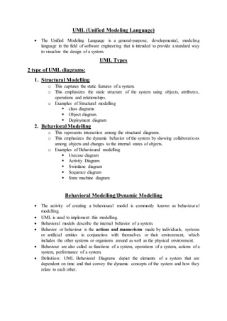
- 1. UML (Unified Modeling Language) The Unified Modeling Language is a general-purpose, developmental, modeling language in the field of software engineering that is intended to provide a standard way to visualize the design of a system. UML Types 2 type of UML diagrams: 1. Structural Modelling o This captures the static features of a system. o This emphasizes the static structure of the system using objects, attributes, operations and relationships. o Examples of Structural modelling class diagrams Object diagram. Deployment diagram 2. Behavioral Modelling o This represents interaction among the structural diagrams. o This emphasizes the dynamic behavior of the system by showing collaborations among objects and changes to the internal states of objects. o Examples of Behavioural modelling Usecase diagram Activity Diagram Swimlane diagram Sequence diagram State machine diagram Behavioral Modelling/Dynamic Modelling The activity of creating a behavioural model is commonly known as behavioural modelling. UML is used to implement this modelling. Behavioral models describe the internal behavior of a system. Behavior or behaviour is the actions and mannerisms made by individuals, systems or artificial entities in conjunction with themselves or their environment, which includes the other systems or organisms around as well as the physical environment. Behaviour are also called as functions of a system, operations of a system, actions of a system, performance of a system. Definition: UML Behavioral Diagrams depict the elements of a system that are dependent on time and that convey the dynamic concepts of the system and how they relate to each other.
- 2. Behavioral model is used to: o Representations of the details of a business process/actions identified by use- cases. o Sequence of operations done by the object o Object States o How the objects interact and form a collaboration to support the use cases. Behavioral model types: o Activity diagram o Usecase diagram o Swimlane diagram o Sequence diagram o State-chart diagram/State machine diagram Example: For example, a behavioral diagram of a vehicle reservation system might contain elements such as Make a Reservation, Rent a Car, and Provide Credit Card Details. Sequence diagram o Sequence diagrams are structured representations of behavior as a series of sequential steps over time. They are used to depict workflow, Message passing and how elements in general cooperate over time to achieve a result. Sequence Diagram A sequence diagram simply depicts interaction between objects in a sequential order i.e. the order in which these interactions take place. Sequence diagrams describe how and in what order the objects in a systemfunction. These diagrams are widely used by businessmen and software developers to document and understand requirements for new and existing systems. Sequence Diagram Notations/Symbols Actors: o An actor in a UML diagram represents a type of role where it interacts with the system and its objects. It is important to note here that an actor is always outside the scope of the system we aim to model using the UML diagram. Figure – notation symbol for actor We use actors to depict various roles including human users and other external subjects. We represent an actor in a UML diagram using a stick person notation.
- 3. Object o Represents a class or object in UML. The object symbol demonstrates how an object will behave in the context of the system. Lifeline symbol o Represents the passage of time as it extends downward. This dashed vertical line shows the sequential events that occur to an object during the charted process. Lifelines may begin with a labeled rectangle shape or an actor symbol.