SlideShare a Scribd company logo
1 of 14
Download to read offline
Maximizing Network Capacity, Reach and Value
Over land, under sea, worldwide www.xtera.com 1
XWDM Solution for 64 Terabit
Optical Networking
XWDM maximizes spectral efficiency AND
spectrum without compromising reach, by
bringing together field-proven technologies,
namely Raman amplification and 30-Gbaud
opto-electronic.
Introduction
Continuous capacity growth – fueled by video
and cloud services – and lower cost per
transported bit are part of the main challenges
any long-haul optical transmission
infrastructure needs to cope with. The advent
at the beginning of this decade of 100G
channel rate, associated with digital coherent
detection, offered a 10-fold capacity increase
compared to networks based on 10G waves.
This impressive line capacity improvement is
achieved with reach performance similar to
what is possible with 10G waves. For some of
the optical impairments experienced by the
waves, like Polarization mode Dispersion
(PMD), the robustness of 100G coherent
detection is actually higher than the one of
10G direct detection, enabling fiber owners to
Maximizing Network Capacity, Reach and Value
Over land, under sea, worldwide www.xtera.com 2
monetize their aged assets, like, e.g., old fibers
with high PMD figures.
As 100G volume production starts, the cost per
10G equivalent is becoming lower with 100G
waves than 10G waves. Although 100G
technology is quite young (for the sake of
comparison, 10G technology is 14-year old
and will be still here within the next several
years), some players of the optical
telecommunication industry are already
pushing for higher channel rates.
The objective of this white paper is to review
the current state of the art and possible options
for the next steps toward higher-capacity
optical networking. This white paper will also
expose Xtera’s vision and approach for
enabling higher-capacity, longer-reach optical
networking using available technologies under
the umbrella of Xtera’s XWDM solution.
Technical Enablers of
100G Networks
100G Channel Rate
Today’s 100G technology makes use of the
PM-QPSK modulation format with coherent
detection (PM: Polarization Multiplexing,
QPSK: Quadrature Phase Shift Keying). 100G
data rate is not achieved by modulating a
single optical carrier using 100G binary
modulation format: this would require opto-
electronics operating at the rate of 100 binary
symbols per second, so at the rate of 100
Gbaud – baud is the unit of symbol rate. Such
opto-electronics speed is not available today
for commercial purpose.
The basic principle of PM-QPSK modulation
format trades speed for parallelism at the
expense of added complexity, as illustrated in
Figure 1.
Figure 1: Principle of PM-QPSK modulation format.
First, two independent orthogonal states of
optical polarization, at the very same optical
frequency (because delivered by the same
single laser source), are modulated. The
polarization multiplexing halves the data rate,
halves the spectral width, but doubles the
count of components.
The next parallelism step encodes the data to
be transported not into 2 states like in any
binary modulation format, but into 4-phase
states. Consequently, a single phase symbol
transports 2 bits of data. The quadrature
phase shift keying halves the symbol rate
compared to the binary phase shift keying. It
also halves the spectral width but doubles the
count of components.
By following this approach, the speed of opto-
electronics components needs to be only
25 Gbaud to transmit and receive a 100-Gbit/s
signal. This 25-Gbaud symbol rate is much
more robust in the face of fiber link
impairments than a 100-Gbaud symbol rate
would. Practically speaking, the line rate of the
100G PM-QPSK signal is closer to 120 Gbit/s
than 100 Gbit/s because of the overhead
added to the client data frame in order to
accommodate OTN mapping as well as the
overhead for forward error correction
Maximizing Network Capacity, Reach and Value
Over land, under sea, worldwide www.xtera.com 3
encoding. 100G PM-QPSK signals actually
require approximately 30-Gbaud opto-
electronics components.
Figure 2 shows a typical implementation of a
100G digital coherent receiver with different
stages: optical polarization splitting, mixing
with an optical local oscillator, QPSK detection,
optical impairments compensation and soft-
decision forward error correction.
Figure 2: Typical implementation of a 100G digital coherent receiver.
Soft-Decision Forward Error
Correction (SD-FEC)
Until very recently, all of the correction codes
that were used in high-speed optical
transmission systems apply correction after the
receiver has produced a one or zero based on
whether the signal is above or below a given
threshold value. It is easy to calculate the gain
for a perfect code of this type. The number of
errors that can be corrected depends on the
number of different parity checks that are
performed. Increasing the number of checks
adds to the overhead, but Figure 3 shows that
increasing the overhead (and thus the
complexity) of the code adds only small
improvements. The squares show examples
of “hard-decision” codes that are utilized.
Increasing the overhead also has the
undesirable effect of increasing the line-rate
and the spectral width of the signal.
A potential solution employs "soft-decision"
correction, where the receiver no longer
produces a stream of binary digits. Instead a
very high speed Analog to Digital Converter
(ADC) produces a multi-bit signal that gives
the amplitude of the detected signal.
This helps because a signal close to the
decision threshold is more likely to be on the
"wrong" side than one that is distant. With this
extra information, and using appropriate
coding and decoding, it is possible in theory to
produce results 3 dB better than the binary
process. Although the decoding process is
extremely complex and requires ultra-high
speed electronics, soft-decision solutions for
100G solutions offer significant advantages
over binary hard-decision codes.
Figure 3: FEC gain vs. overhead.
With the above techniques, Xtera achieves a
net coding gain in the range of 1.5 to 2 dB.
Xtera was the first optical networking
equipment vendor to deploy 100G SD-FEC in
a commercial network (in 2011 in a 22,000 km
backbone network in Mexico).
5
FEC overhead (%)
Hard-decision
theoretical limit
10 15 20 25 30
5
6
7
8
9
10
11
Netcodinggain(dB)
12
13
Using 6 bit soft-decision decoding
RS 239,255
Maximizing Network Capacity, Reach and Value
Over land, under sea, worldwide www.xtera.com 4
Figure 4: 100G interface cards with 10 client interfaces at 10G and soft-decision FEC.
Performance of 100G Optical
Networks
The combination of PM-QPSK modulation,
coherent detection, digital signal processing,
and soft-decision forward error correction
satisfies today’s capacity and reach needs.
Using standard Erbium-Doped Fiber Amplifiers
(EDFAs), line capacity of about 9 Tbit/s per
fiber pair can be achieved on 2,000 km reach
with no intermediate signal regeneration.
100G waves can propagate on standard G.652
fibers (which forms by far the largest portion of
the terrestrial fiber infrastructures installed as
of today) with no need for optical
compensation of the fiber chromatic dispersion
(the chromatic dispersion compensation is
carried out in the electrical domain by the
digital coherent receiver): this leads to the
lowest latency that can be achieved in optical
cable. Lastly the robustness to PMD exceeds
30 ps, i.e. 3 times larger than the tolerance
with 10G direct detection!
Current 100G coherent technology offers
network operators the possibility to boost the
capacity of their existing fiber asset with no
significant reach reduction compared to what
was achievable with 10G technology.
Further incremental improvements of 100G
coherent technology are still to come with
more compact interface cards, lower power
consumption, further cost reductions, more
powerful digital signal processing and higher
net coding gain from enhanced soft-decision
forward error correction for improved
transmission performance.
Toward Higher Capacity
Optical Networking: The
Standard Approach
Options for Increasing Line
Capacity
The key constraint is the limitation of the speed
of opto-electronics devices, which is today and
in the near future in the range of 30 Gbaud.
Starting from this constraint, which imposes
the upper limit of 30 giga (30 x 10
9
) symbols
per second, two main approaches are pursued
in the telecom industry: the first approach is to
increase the number of bits per symbol; the
second one is to pack more densely the optical
carriers within the available optical spectrum.
Higher Number of Bits per Symbol
Current 100G technology is based on
Quadrature Phase Shift Keying (QPSK)
modulation format. The phase of the optical
signal is modulated and can take 4 different
states (e.g. 45°, 135°, 225° and 315°), while
Maximizing Network Capacity, Reach and Value
Over land, under sea, worldwide www.xtera.com 5
the amplitude remains constant. Two bits per
symbol are required to encode four phase
states (e.g. 11 for 45°, 01 for 135°, 00 for 225°
and 10 for 315°) as illustrated in Figure 5.
Figure 5: QPSK and 16QAM constellation diagrams.
With 16 Quadrature Amplitude Modulation
(16QAM) modulation format, both the phase
and the amplitude of the optical signal are
modulated to give 16 different amplitude-phase
combinations; 4 bits are then required to
encode these 16 states (e.g. 0000 for phase-
amplitude state # 1, 1111 for phase-amplitude
state # 16). PM-16QAM modulation format
doubles both the bit rate and the spectral
efficiency (expressed in bit/s/Hz – where Hz is
the bandwidth unit of the transmission
medium) for the same symbol clock compared
to PM-QPSK. Playing with 30-Gbaud symbol
rate, PM-16QAM format leads to 200G data
rate and a spectral efficiency of 4 bit/s/Hz.
The counterpart of this higher number of states
of the signal – or, equivalently, of bits per
symbol – is the higher sensitivity on noise and
other corruptions brought by propagation
inside the optical fiber. Assuming EDFA
amplifiers, 50-Ghz channel spacing, 0.2-dB
fiber attenuation, about 80-km spans and 3-dB
margin per span, 200G PM-16QAM can
propagate on about 800 km before signal
regeneration is required in order to ensure
proper recovery of the data. This needs to be
compared to 2,000-km reach performance for
100G PM-QPSK signals in the same span/fiber
conditions. When longer spans or higher fiber
loss are encountered in real network
conditions, these reach figures are drastically
reduced.
Now that we have built a 200G optical carrier,
two carriers can be combined to build a 400G
optical channel (such a 400G signal is named
DC PM-16QAM, where DC stands for Dual
Carrier). An example of implementation is
depicted in Figure 5.
Figure 5: Example of implementation for a 400G channel made of two 200G carriers (DC PM-16QAM).
Maximizing Network Capacity, Reach and Value
Over land, under sea, worldwide www.xtera.com 6
The standard implementation employs 50-GHz
spacing between the two carriers and is
nothing more than the multiplexing of 200G
waves on the standard 50-GHz grid.
Compared to 100G waves, the line capacity is
effectively doubled, from typically 8.8 to
17.6 Tbit/s, but the transmission reach is more
than halved as discussed above.
More Densely Packed Carriers
Another way to further increase the spectral
efficiency and the line capacity is to reduce the
inter-carrier spacing, walking away from the
standard 50-GHz spacing down to narrower
spacing like, e.g., 37.5 GHz. Because of the
presence of sidebands in the spectrum of any
modulated digital signal, the narrower the
carrier spacing is, the higher the interference
level is. To effectively enable smaller carrier
spacing, it may be necessary to shape the
spectrum of the carriers at the transmit end in
order to eliminate the side bands. Spectral
shaping not only enables smaller spacing
between carriers but also reduces the filtering
distortion caused by, e.g., cascaded
Reconfigurable Optical Add Drop Multiplexers
(ROADMs).
Driven by the interface card technology or the
optical multiplexing-demultiplexing architecture
of the optical equipment, carriers spaced by
less than 50 GHz are often grouped into a
channel whose capacity is a multiple of the
carrier capacity. For example, a 1-Tbit/s
channel can be built by combining ten 100G
PM-QPSK carriers or five 200G DC PM-
16QAM carriers spaced 37.5 and 50 GHz
apart, respectively, as depicted in Figure 6.
Figure 6: Two ways to build a 1-Tbit/s channel.
There are actually an infinite number of
combinations to build multiple-carrier channels,
playing with the capacity, spacing and number
of carriers.
The inter-carrier spacing can be reduced to
increase further the spectral efficiency, at the
expense of degraded reach performance.
Assuming 100G PM-QPSK carriers, moving
from 50- to 37.5-GHz spacing increases the
line capacity by 1.1 dB (from 8.8 to 11.6 Tbit/s
for EDFA-constrained link), but decreases in
the same time the reach by 1.9 dB. Narrow
inter-carrier spacing enables fatter but shorter
pipes, with the net result of reducing the
[Capacity x Reach] metric of the system.
Combining More Bits per Symbol and
Narrower Inter-Carrier Spacing
Both approaches can be combined to reach a
spectral efficiency in excess of 5 bit/s/Hz as
illustrated in Figure 7.
Figure 7: Spectral efficiency and all-optical reach for
various carrier modulation and spacing strategies for
EDFA-based systems.
Figure 7 also clearly shows the dramatic
decrease in all-optical reach that accompanies
the increase in the spectral efficiency: when
the spectral efficiency goes from 2 up to
5.3 bit/s/Hz, the reach goes downwards from
2,000 to about 400 km.
Limitations of Traditional Approach
Within the 30-Gbaud speed constraint for the
symbol rate, there are some solutions to
increase the line capacity of current 100G
optical networking products. Today, the line
capacity that is typically offered is
Maximizing Network Capacity, Reach and Value
Over land, under sea, worldwide www.xtera.com 7
88 x 100G = 8.8 Tbit/s. 200G PM-16QAM
carriers spaced 37.5 GHz apart could lead to a
line capacity of about 23 Tbit/s but with a reach
limited to 400 km in very specific network
conditions. If some spans are longer than
80 km or if some fiber portions attenuate the
signals by more than 0.2 dB/km, the 400-km
reach figure will significantly drop and be
inappropriate for real-world backbone
applications.
EDFA amplification technology limits the
[Capacity x Reach] performance in two ways:
 The optical spectrum is limited to a
maximum of 38 nm: packing more
carriers means narrower spacing and
stronger inter-carrier optical
impairments inside the optical fiber.
 EDFAs represent hot spots, boosting
the signals power periodically along
the optical links: such a power profile
is conducive to nonlinearities within
the line fiber at the beginning of each
span. Although very powerful to
compensate for linear degradations
(like chromatic dispersion and PMD),
the digital signal processing of
coherent receiver is not yet effective in
compensating for nonlinear
degradations.
Lastly, EDFA noise performance is not optimal,
resulting in a significant noise accumulation
along the optical path with multiple in-line
amplifiers. This noise accumulation degrades
the Optical Signal-to-Noise Ratio (OSNR)
experienced by the optical channels and limits
the [Capacity x Reach] metric.
Raman Amplification to
Unleash Line Capacity and
Reach
Amplifier Wish List
Line equipment with wider optical spectrum is
obviously one of the first requirements. Wider
spectrum means more waves than can fit into
the amplifier spectrum and/or larger spacing
between carriers to reduce the amount of
interference and nonlinearities between the
carriers.
Noise performance is also a key parameter for
optical transport over long distances. Because
the OSNR requirements are more stringent
when the channel rate (driven by the number
of symbols per seconds and the number of bits
per symbol) increases, reducing the amount of
optical noise generated by a string of optical
amplifiers is critical for increasing the
unregenerated reach.
Another key item on the ideal amplifier wish list
is the capability to limit the amount and
efficiency of nonlinearities. As most of the
terrestrial deployments happen on existing
fiber infrastructures, installing less nonlinearity-
sensitive fibers with, e.g., larger effective core
area is not an option. Therefore an
amplification technology that avoids “hot
points” inside the line fiber between the ingress
and egress points of the optical paths is of
paramount importance.
Benefits from Raman Amplification
Raman amplification is an effective answer to
meet these three key requirements:
 Raman-based optical amplifiers offer
up to with 100-nm bandwidth (such
amplifiers were deployed by Xtera in
as soon as 2004);
 Superior noise performance of
Raman-based optical amplifiers leads
to higher OSNR performance at the
output end of the optical path;
 Distributed Raman amplification within
the line fiber results in a lower peak-to-
peak power excursion along the
optical path, reducing the amount of
nonlinearities.
Another way to describe Raman amplification
benefits is to consider two dimensions with
respect to the direction of transmission in the
line fiber. In the transversal dimension,
Raman optical amplification offers a broader
spectrum beyond the spectral bottleneck
imposed by EDFA amplifiers. In the
longitudinal direction, Raman optical
amplification has the ability to extend reach
thanks to better noise performance and
distributed amplification within the line fiber
Maximizing Network Capacity, Reach and Value
Over land, under sea, worldwide www.xtera.com 8
(instead of being a purely passive transmission
medium, some portions of the optical spans
can provide the optical carriers with optical
gain).
Broader Spectrum with Raman Amplification
Figure 8 is a simple way to illustrate the
spectrum benefit offered by Raman optical
amplification.
Figure 8: Typical optical spectral and channel counts (assuming 50-GHz channel spacing) offered by different optical
amplification technologies.
The optical spectrum of EDFA amplifier
typically ranges from 32 to 38 nm. Xtera’s
EDFA supports a 37-nm spectrum width that
enables the multiplexing of up to 93 channels
spaced 50 GHz apart.
When Raman pumping modules are added to
an EDFA amplifier in order to build optical gain
inside the line fiber, the resulting spectrum
width cannot exceed the one of EDFA amplifier
(like in the cascade of band-pass filters, the
bandwidth of the combined filters is strongly
governed by the narrowest bandwidth).
To go beyond the conventional spectral band
(C band) offered by EDFA amplifier, one needs
to get rid of the spectral bottleneck imposed by
Erbium ions in the EDFA approach and switch
to another optical amplification technology.
Raman optical amplification enables building
optical from spectrum up to 100-nm width by
combining several optical pump sources at
different wavelengths as illustrated in Figure 9.
Xtera has developed different flavors of
Raman optical amplification:
 Raman implementation: its 61-nm
spectrum can accommodate up to 150
optical carriers assuming 50-GHz
channel spacing;
 Raman+ implementation: its extended
100-nm spectrum can support up to
240 optical carriers, spaced 50 GHz
apart.
Figure 9: Basic principle of Raman
optical amplification.
Extended Reach with Raman Amplification
The higher the fiber attenuation, the more
optical gain is required to compensate for the
loss in the power of the transmitted signals.
However, optical gain, like electronic gain, is
achieved at the expense of noise added to the
signals. As a result, the OSNR of the optical
carriers is degraded by fiber loss and optical
amplification. The optical signals cannot
experience attenuation levels which are too
elevated otherwise the data will be corrupted
by the optical noise, with no way to properly
Maximizing Network Capacity, Reach and Value
Over land, under sea, worldwide www.xtera.com 9
recover their integrity at the output end of the
optical link. The optical noise imposes a lower
limit on the per wavelength power along the
optical fiber.
Nonlinearities in silica optical fiber are caused
by the Kerr effect. The Kerr effect describes
the dependency of the refractive index of the
optical waveguide on the instantaneous optical
intensity. The higher the signal power, the
higher the nonlinearities and the subsequent
distortions that are experienced by the optical
signals. Nonlinearities impose an upper limit
on the per wavelength power that can be
launched into the optical fiber.
Because of the upper limit for per channel
power set by nonlinear effects and the lower
limit imposed by minimal OSNR requirement,
the per channel optical power profile must fit
within some kind of “optical power tunnel” in
order to guarantee data integrity along the
optical fiber.
Figure 10: “Optical power tunnel” for maintaining optical
signal integrity.
This “optical power tunnel” is illustrated above
in Figure 10: as soon as the per channel power
hits either the upper or lower limit, the quality
of the data carried by the optical channel is
irreparably impacted.
Figure 11: Typical per channel optical power profile as a function of the transmission distance
in chains of EDFA and Raman amplifiers
Maximizing Network Capacity, Reach and Value
Over land, under sea, worldwide www.xtera.com 10
The management of per channel power is
quite different in an optical transmission
system relying on Raman amplification. Here,
the line fiber is not only a transmission medium
bringing optical attenuation to the optical
channels but also a gain medium because of
the distributed Raman amplification effect
occurring inside the line fiber when Raman
pump waves are launched into the line fiber.
In the backward Raman implementation, the
Raman pumps are launched upstream from
the repeater site into the preceding fiber span,
in a counter direction compared to the direction
of transmission for optical channels.
In the forward Raman implementation, the
Raman pumps are launched downstream, from
the repeater site into the following fiber span,
in the same direction as the direction of
transmission for optical channels.
Figure 11 above illustrates the evolution of the
per channel optical power along a link made of
several spans and in-line Raman amplifiers.
The net result is a lower peak-to-peak power
excursion along the optical path compared to
the EDFA chain, keeping the optical signals
away from noise and nonlinear impairments.
Reach wise, the benefit offered by distributed
Raman amplification is two-fold:
 Possibility to design and implement all-
optical links with ultra-long end-to-end
reach because the degrading effects that
accumulate with the transmission distance
are mitigated:
o Improvement of the link OSNR
performance
o Reduction in the amount of
nonlinearities distorting the optical
signals
 Possibility to bridge longer spans than
EDFA-based systems
The second benefit (long span capabilities) is
symbolized in Figure 11 by the span between
in-line amplifiers E and F: distributed Raman
amplification inside the line fiber not only limits
the OSNR degradation and nonlinear
impairments along the transmission but also
enables longer spacing between sites E and F.
In short, better noise performance and lower
peak power inside the optical fiber are the two
key features offered by distributed Raman
amplification that enable both long end-to-end
reach and long spans between adjacent sites.
Achievements with Raman
Amplification
In the past years, and in real networks
environments, Raman amplifications allowed
the following 100G link implementations with
Xtera’s Nu-Wave Optima
TM
optical networking
platform:
 1,300-km all-optical route including a
250-km / 60-dB span; with the
common EDFA approach, the
channels would have to be terminated
at either end of this 250-km, 60-dB
span, imposing costly regeneration
sites;
 2,500-km, 24-span all-optical route;
this length represents the longest
100G all-optical link ever deployed in
real field conditions, with practical fiber
attenuation, standard margin per span
for repair and non-uniform span
lengths (up to 227 km) as found in real
network environments;
 7 Tbit/s per fiber pair on a 350-km /
65.5-dB unrepeatered link (with 34 x
100G recently demonstrated on a 436-
km link).
In its original configuration, Nu-Wave Optima
TM
platform supported line capacity of 15 Tbit/s,
made of 150 carriers at 100G each.
More recently Xtera conducted extensive lab
and field trials, using the same Nu-Wave
Optima
TM
platform, in order to confirm the
value of Raman optical amplification for higher
line rate with ultra-long-haul capabilities.
Maximizing Network Capacity, Reach and Value
Over land, under sea, worldwide www.xtera.com 11
XWDM Solution for
Unparalleled Reach and
Capacity Performance
Drivers to XWDM
Conventional optical networking products are
typically built around EDFA amplification that
presents several limitations as previously
listed: far from optimal optical noise
performance, generation of nonlinearities at
the beginning of each fiber span and narrow
optical spectrum. As a result, increase in line
capacity by moving from 100G to 400G
channel rate (made of, e.g., two carriers, each
carrying 200G using PM-16QAM) and/or
decreasing the channel spacing strongly
reduces the reach.
16QAM modulation format with EDFA
amplification will work only for a limited number
of applications in the real world, being
understood that backbone operators will not go
to the expense of putting in intermediate signal
regeneration to employ this technology.
Regeneration sites represent many drawbacks
for the operators, such as: high power
consumption, large space requirements and
points of lower reliability. Beyond these OpEx
issues, regeneration sites are also very costly
when the network capacity grows because
interface cards must be deployed for each new
wavelength put in service (contrary to an
amplification site where all of the waves
present in the line share the cost of the
amplifier). Regeneration sites imply
significantly higher incremental cost and longer
lead time when placing new capacity into
service compared to an optically-amplified link
implementation. The incremental cost for
added capacity is all the higher since the data
rate supported by the optical wavelengths is
high. For all these reasons, it is of the utmost
importance to avoid or minimize the number of
regeneration sites for long light paths in order
to build a cost-effective optical network.
XWDM Solution
Bringing together current opto-electronics
technology (offering 30-Gbaud symbol rate)
and Raman optical amplification, XWDM is
Xtera’s solution to enable 100G and Beyond
100G optical networking with ultra-long reach.
Raman amplification, with better noise
performance and smaller amount of
nonlinearities generated in the line fiber
compared EDFA amplification, typically
enables a two-fold increase in the reach as
illustrated by Figure 12.
Figure 12: “All-optical reach as a function of modulation
format for different optical amplification options.
Additionally Raman amplification offers up to
three-fold increase in the optical spectrum
width, providing more room (up to 100 nm) for
multiplexing optical carriers. Xtera developed
two all-Raman implementations: Raman with
61-nm spectrum, and Raman+ with 100-nm
spectrum.
Figure 13: “[Capacity x Reach] metric as a function of
modulation format and for different
optical amplification options.
Maximizing Network Capacity, Reach and Value
Over land, under sea, worldwide www.xtera.com 12
Figure 13 represents the [Capacity x Reach]
performance for different combinations of
modulation formats and line equipment
technology (EDFA, Raman or Raman+).
For a given amplifier technology, [Capacity x
Reach] metric is about constant, independently
on the spectral efficiency.
Raman amplification with 100-nm spectrum
enables 6 times higher [Capacity x Reach]
metric compared to EDFA amplification.
XWDM can transmit 240 waves at 100G each
(total of 24 Tbit/s) on more than 4,500 km with
no need for intermediate regeneration. Using
PM-16QAM modulation format and various
inter-carrier spacings, XWDM can also
transmit a line capacity of 48 Tbit/s and
64 Tbit/s on 2,000 and 1,500 km, respectively.
Figure 14 summarizes the two key
components of XWDM solution and the way
they interplay to build up the combination of
capacity and reach for optical transmission.
Figure 14: XWDM components.
The first XWDM component is the selector of
modulation format and carrier spacing. Using
30-Gbaud opto-electronics, 100G, 400G or 1T
channels can be built with the combination of
100G PM-QPSK or 200G PM-16QAM carriers.
The inter-carrier spacing is an additional
parameter that enables the setting of the
spectral efficiency and thus the line capacity
for a given line spectrum.
The second XWDM component is the optical
spectrum shaper. As soon as EDFA amplifiers
are used in the line equipment, the spectrum is
constrained by the spectral EDFA bottleneck
(37 nm for Xtera’s equipment). The simple
addition of Raman modules to extend the
reach between spans cannot widen this optical
spectrum. In addition to EDFA or hybrid
EDFA/Raman amplification, Xtera offers two
all-Raman implementations: Raman with 61-
nm spectrum, and Raman+ with 100-nm
spectrum. Hence Xtera’s Nu-Wave Optima
TM
optical networking platform offers the choice
between three optical spectrum widths – 37,
61 and 100 nm – corresponding to 93, 150 and
240 channels spaced 50 GHz apart,
respectively.
Although sometimes considered in the past as
an over-engineered solution for 10G
networking, today the industry considers
Raman optical amplification to be a critical
enabler for efficient 100G and Beyond 100G
long-haul networking in field conditions
(including aged fibers, non-uniform span
lengths, multiple optical distribution frames,
connectors, and fiber repairs along the optical
path).
Unlike competitive offerings where integrating
optical Raman amplifier with EDFA was an
Maximizing Network Capacity, Reach and Value
Over land, under sea, worldwide www.xtera.com 13
afterthought, Xtera designed its Nu-Wave
Optima
TM
optical networking platform from the
ground up to combine different optical
amplification flavors, ranging from simple
EDFA to all-distributed Raman amplification.
One key concern in the design and
development phases of Xtera’s Raman
amplifiers was to offer equipment as simple, if
not simpler, to operate as EDFA-based
equipment. Xtera’s Raman amplifier sub-
system has proved to offer high efficiency,
excellent reliability and unparalleled reach-
performance due to the high integration of the
different optical amplification technologies.
Xtera deployed in 2004 Raman amplifiers with
100nm spectrum; these amplifiers are still
running today.
More fundamentally, in information theory, the
Shannon–Hartley theorem tells the maximum
rate at which information can be transmitted
over a communications channel of a specified
bandwidth in the presence of noise. Optical
spectrum and OSNR are the fundamentally
limiting factors for optical communications.
Raman amplification helps network designers
increase network capacity thanks to its
significantly better spectral and noise
performances compared to EDFA
amplification.
Conclusion
Combining current opto-electronics technology
(the one utilized today to build 100G channels)
and Raman optical amplification (as deployed
by Xtera in the last decade), Xtera’s XWDM
solution enables 100G and Beyond 100G
optical networking with ultra-high capacity and
ultra-long reach.
XWDM solution was validated by commercial
deployments and extensive lab and field trials,
some of them in the Verizon network, using
Xtera’s commercial optical networking Nu-
Wave Optima
TM
platform.
Xtera’s XWDM enables high spectral efficiency
AND wide optical spectrum without
compromising reach. Limited reach with 400G
channels and EDFA amplifiers is a critical
issue for backbone applications. XWDM offers
64T line capacity on more than 1,500 km in
field conditions by combining 200G carriers
and 100nm optical spectrum.
Beyond the raw benefits in terms of capacity
and reach, XWDM offers more linear optical
propagation inside the line fiber, simplifying
restoration rerouting in meshed configuration.
XWDM also supports more channels for higher
capacity headroom, broader spectrum for
spectrum sharing applications, and lower
incremental cost when new capacity is added
due to the minimization of regeneration sites.
Maximizing Network Capacity, Reach and Value
Over land, under sea, worldwide www.xtera.com 14
Maximizing Network Capacity, Reach and Value
Over land, under sea, worldwide
Edition Date: December 2013
Version: 1.0

More Related Content

What's hot

High capacity optical
High capacity opticalHigh capacity optical
High capacity opticalNisha Menon K
 
White Paper: Real-Time Monitoring of Passive Optical Networks
White Paper: Real-Time Monitoring of Passive Optical NetworksWhite Paper: Real-Time Monitoring of Passive Optical Networks
White Paper: Real-Time Monitoring of Passive Optical NetworksSusmita Adhikari Joshi
 
7148806 nafeel-edge
7148806 nafeel-edge7148806 nafeel-edge
7148806 nafeel-edgePawan Bisht
 
HIGH SPEED WIRELESS COMMUNICATION
HIGH SPEED WIRELESS COMMUNICATIONHIGH SPEED WIRELESS COMMUNICATION
HIGH SPEED WIRELESS COMMUNICATIONRezaul Islam
 
ROADM Technologies for Flexible - Tbitsec Optical Networks
ROADM Technologies for Flexible - Tbitsec Optical NetworksROADM Technologies for Flexible - Tbitsec Optical Networks
ROADM Technologies for Flexible - Tbitsec Optical NetworksCPqD
 
Next-Generation High-Capacity Submarine Transmission
Next-Generation High-Capacity Submarine TransmissionNext-Generation High-Capacity Submarine Transmission
Next-Generation High-Capacity Submarine TransmissionCPqD
 
Performance Analysis of BER and Throughput of Different MIMO Systems using Di...
Performance Analysis of BER and Throughput of Different MIMO Systems using Di...Performance Analysis of BER and Throughput of Different MIMO Systems using Di...
Performance Analysis of BER and Throughput of Different MIMO Systems using Di...IRJET Journal
 
Powerful business model for fixed wireless data using outdoor antennas - Paper
Powerful business model for fixed wireless data using outdoor antennas - PaperPowerful business model for fixed wireless data using outdoor antennas - Paper
Powerful business model for fixed wireless data using outdoor antennas - PaperAndre Fourie
 
Slide fyp ver3
Slide fyp ver3Slide fyp ver3
Slide fyp ver3yusriyacob
 
TECHNIQUES TO COMBAT OSNR IN DWDM LINKS
TECHNIQUES TO COMBAT OSNR IN DWDM LINKSTECHNIQUES TO COMBAT OSNR IN DWDM LINKS
TECHNIQUES TO COMBAT OSNR IN DWDM LINKSMapYourTech
 
An experimental overview on software defined optical transmission and sdngmpl...
An experimental overview on software defined optical transmission and sdngmpl...An experimental overview on software defined optical transmission and sdngmpl...
An experimental overview on software defined optical transmission and sdngmpl...CPqD
 
Orchestration of Ethernet Services in Software-Defined and Flexible Heterogen...
Orchestration of Ethernet Services in Software-Defined and Flexible Heterogen...Orchestration of Ethernet Services in Software-Defined and Flexible Heterogen...
Orchestration of Ethernet Services in Software-Defined and Flexible Heterogen...ADVA
 
OFC 2019 - 100G DWDM DCI/Metro Network Solutions - Debating alternatives to ...
OFC 2019 -  100G DWDM DCI/Metro Network Solutions - Debating alternatives to ...OFC 2019 -  100G DWDM DCI/Metro Network Solutions - Debating alternatives to ...
OFC 2019 - 100G DWDM DCI/Metro Network Solutions - Debating alternatives to ...Tim Yount
 
5G NR Coverage Analysis for 700 MHz
5G NR Coverage Analysis for 700 MHz 5G NR Coverage Analysis for 700 MHz
5G NR Coverage Analysis for 700 MHz Eiko Seidel
 
Pathloss based power control technique in heterogeneous network
Pathloss based power control technique in heterogeneous networkPathloss based power control technique in heterogeneous network
Pathloss based power control technique in heterogeneous networkEzhilazhahi AM
 
Optical Networking Trends & Evolution
Optical Networking Trends & EvolutionOptical Networking Trends & Evolution
Optical Networking Trends & EvolutionADVA
 
White Paper: Evolving Technolgies for Mobile Front and Backhauling
White Paper: Evolving Technolgies for Mobile Front and BackhaulingWhite Paper: Evolving Technolgies for Mobile Front and Backhauling
White Paper: Evolving Technolgies for Mobile Front and BackhaulingSusmita Adhikari Joshi
 
Comparative TCO of microwave backhaul systems
Comparative TCO of microwave backhaul systemsComparative TCO of microwave backhaul systems
Comparative TCO of microwave backhaul systemsCBNL
 

What's hot (20)

High capacity optical
High capacity opticalHigh capacity optical
High capacity optical
 
White Paper: Real-Time Monitoring of Passive Optical Networks
White Paper: Real-Time Monitoring of Passive Optical NetworksWhite Paper: Real-Time Monitoring of Passive Optical Networks
White Paper: Real-Time Monitoring of Passive Optical Networks
 
7148806 nafeel-edge
7148806 nafeel-edge7148806 nafeel-edge
7148806 nafeel-edge
 
HIGH SPEED WIRELESS COMMUNICATION
HIGH SPEED WIRELESS COMMUNICATIONHIGH SPEED WIRELESS COMMUNICATION
HIGH SPEED WIRELESS COMMUNICATION
 
ROADM Technologies for Flexible - Tbitsec Optical Networks
ROADM Technologies for Flexible - Tbitsec Optical NetworksROADM Technologies for Flexible - Tbitsec Optical Networks
ROADM Technologies for Flexible - Tbitsec Optical Networks
 
Next-Generation High-Capacity Submarine Transmission
Next-Generation High-Capacity Submarine TransmissionNext-Generation High-Capacity Submarine Transmission
Next-Generation High-Capacity Submarine Transmission
 
Performance Analysis of BER and Throughput of Different MIMO Systems using Di...
Performance Analysis of BER and Throughput of Different MIMO Systems using Di...Performance Analysis of BER and Throughput of Different MIMO Systems using Di...
Performance Analysis of BER and Throughput of Different MIMO Systems using Di...
 
Powerful business model for fixed wireless data using outdoor antennas - Paper
Powerful business model for fixed wireless data using outdoor antennas - PaperPowerful business model for fixed wireless data using outdoor antennas - Paper
Powerful business model for fixed wireless data using outdoor antennas - Paper
 
Slide fyp ver3
Slide fyp ver3Slide fyp ver3
Slide fyp ver3
 
TECHNIQUES TO COMBAT OSNR IN DWDM LINKS
TECHNIQUES TO COMBAT OSNR IN DWDM LINKSTECHNIQUES TO COMBAT OSNR IN DWDM LINKS
TECHNIQUES TO COMBAT OSNR IN DWDM LINKS
 
An experimental overview on software defined optical transmission and sdngmpl...
An experimental overview on software defined optical transmission and sdngmpl...An experimental overview on software defined optical transmission and sdngmpl...
An experimental overview on software defined optical transmission and sdngmpl...
 
Orchestration of Ethernet Services in Software-Defined and Flexible Heterogen...
Orchestration of Ethernet Services in Software-Defined and Flexible Heterogen...Orchestration of Ethernet Services in Software-Defined and Flexible Heterogen...
Orchestration of Ethernet Services in Software-Defined and Flexible Heterogen...
 
5G
5G5G
5G
 
OFC 2019 - 100G DWDM DCI/Metro Network Solutions - Debating alternatives to ...
OFC 2019 -  100G DWDM DCI/Metro Network Solutions - Debating alternatives to ...OFC 2019 -  100G DWDM DCI/Metro Network Solutions - Debating alternatives to ...
OFC 2019 - 100G DWDM DCI/Metro Network Solutions - Debating alternatives to ...
 
5G NR Coverage Analysis for 700 MHz
5G NR Coverage Analysis for 700 MHz 5G NR Coverage Analysis for 700 MHz
5G NR Coverage Analysis for 700 MHz
 
Pathloss based power control technique in heterogeneous network
Pathloss based power control technique in heterogeneous networkPathloss based power control technique in heterogeneous network
Pathloss based power control technique in heterogeneous network
 
Optical Networking Trends & Evolution
Optical Networking Trends & EvolutionOptical Networking Trends & Evolution
Optical Networking Trends & Evolution
 
White Paper: Evolving Technolgies for Mobile Front and Backhauling
White Paper: Evolving Technolgies for Mobile Front and BackhaulingWhite Paper: Evolving Technolgies for Mobile Front and Backhauling
White Paper: Evolving Technolgies for Mobile Front and Backhauling
 
Optical Networking & DWDM
Optical Networking & DWDMOptical Networking & DWDM
Optical Networking & DWDM
 
Comparative TCO of microwave backhaul systems
Comparative TCO of microwave backhaul systemsComparative TCO of microwave backhaul systems
Comparative TCO of microwave backhaul systems
 

Similar to Maximizing Network Capacity with 64 Terabit Optical Networking

optical space division multiplexing
optical space division multiplexingoptical space division multiplexing
optical space division multiplexingmohammedalimahdi
 
Ericsson Review: Overcoming the challenges of very high-speed, terabit optica...
Ericsson Review: Overcoming the challenges of very high-speed, terabit optica...Ericsson Review: Overcoming the challenges of very high-speed, terabit optica...
Ericsson Review: Overcoming the challenges of very high-speed, terabit optica...Ericsson
 
Edge Seminar
Edge SeminarEdge Seminar
Edge Seminartijeel
 
Newtec - Optimisation of Satellite Capacity Efficiency for IP Trunking Applic...
Newtec - Optimisation of Satellite Capacity Efficiency for IP Trunking Applic...Newtec - Optimisation of Satellite Capacity Efficiency for IP Trunking Applic...
Newtec - Optimisation of Satellite Capacity Efficiency for IP Trunking Applic...Sematron UK Ltd
 
IEEE 2014 NS2 NETWORKING PROJECTS Optical networking with variable code-rate...
IEEE 2014 NS2 NETWORKING PROJECTS  Optical networking with variable code-rate...IEEE 2014 NS2 NETWORKING PROJECTS  Optical networking with variable code-rate...
IEEE 2014 NS2 NETWORKING PROJECTS Optical networking with variable code-rate...IEEEBEBTECHSTUDENTPROJECTS
 
Public Switched Telephone Network (PSTN)
Public Switched Telephone Network (PSTN)Public Switched Telephone Network (PSTN)
Public Switched Telephone Network (PSTN)J.T.A.JONES
 
mstp_ofc05_abstract_updated
mstp_ofc05_abstract_updatedmstp_ofc05_abstract_updated
mstp_ofc05_abstract_updatedLoukas Paraschis
 
Analysis of System Capacity and Spectral Efficiency of Fixed-Grid Network
Analysis of System Capacity and Spectral Efficiency of Fixed-Grid NetworkAnalysis of System Capacity and Spectral Efficiency of Fixed-Grid Network
Analysis of System Capacity and Spectral Efficiency of Fixed-Grid NetworkIJCNCJournal
 
PLNOG 8: Norbert Gulczyński - 100G w sieciach szkieletowych i miejskich
PLNOG 8: Norbert Gulczyński - 100G w sieciach szkieletowych i miejskich PLNOG 8: Norbert Gulczyński - 100G w sieciach szkieletowych i miejskich
PLNOG 8: Norbert Gulczyński - 100G w sieciach szkieletowych i miejskich PROIDEA
 
Sspi day out_2014_comtech-leonardo_gil
Sspi day out_2014_comtech-leonardo_gilSspi day out_2014_comtech-leonardo_gil
Sspi day out_2014_comtech-leonardo_gilSSPI Brasil
 
IP-optical convergence: a complete solution
IP-optical convergence: a complete solutionIP-optical convergence: a complete solution
IP-optical convergence: a complete solutionEricsson
 
The coherent optical edge
The coherent optical edgeThe coherent optical edge
The coherent optical edgeADVA
 
IRJET - 5G Architecture using GAN based Digital Transmitter in VLSI Desig...
IRJET -  	  5G Architecture using GAN based Digital Transmitter in VLSI Desig...IRJET -  	  5G Architecture using GAN based Digital Transmitter in VLSI Desig...
IRJET - 5G Architecture using GAN based Digital Transmitter in VLSI Desig...IRJET Journal
 
5G New Radio Technology Throughput Calculation
5G New Radio Technology  Throughput Calculation5G New Radio Technology  Throughput Calculation
5G New Radio Technology Throughput CalculationSukhvinder Singh Malik
 
PPC-10G Press Release
PPC-10G Press ReleasePPC-10G Press Release
PPC-10G Press ReleaseJohn Stover
 

Similar to Maximizing Network Capacity with 64 Terabit Optical Networking (20)

optical space division multiplexing
optical space division multiplexingoptical space division multiplexing
optical space division multiplexing
 
IESL Technical paper_2015 AGM
IESL Technical paper_2015 AGMIESL Technical paper_2015 AGM
IESL Technical paper_2015 AGM
 
Ericsson Review: Overcoming the challenges of very high-speed, terabit optica...
Ericsson Review: Overcoming the challenges of very high-speed, terabit optica...Ericsson Review: Overcoming the challenges of very high-speed, terabit optica...
Ericsson Review: Overcoming the challenges of very high-speed, terabit optica...
 
Edge Seminar
Edge SeminarEdge Seminar
Edge Seminar
 
Newtec - Optimisation of Satellite Capacity Efficiency for IP Trunking Applic...
Newtec - Optimisation of Satellite Capacity Efficiency for IP Trunking Applic...Newtec - Optimisation of Satellite Capacity Efficiency for IP Trunking Applic...
Newtec - Optimisation of Satellite Capacity Efficiency for IP Trunking Applic...
 
Newtec FlexACM
Newtec FlexACMNewtec FlexACM
Newtec FlexACM
 
IEEE 2014 NS2 NETWORKING PROJECTS Optical networking with variable code-rate...
IEEE 2014 NS2 NETWORKING PROJECTS  Optical networking with variable code-rate...IEEE 2014 NS2 NETWORKING PROJECTS  Optical networking with variable code-rate...
IEEE 2014 NS2 NETWORKING PROJECTS Optical networking with variable code-rate...
 
Edge
EdgeEdge
Edge
 
Public Switched Telephone Network (PSTN)
Public Switched Telephone Network (PSTN)Public Switched Telephone Network (PSTN)
Public Switched Telephone Network (PSTN)
 
mstp_ofc05_abstract_updated
mstp_ofc05_abstract_updatedmstp_ofc05_abstract_updated
mstp_ofc05_abstract_updated
 
Analysis of System Capacity and Spectral Efficiency of Fixed-Grid Network
Analysis of System Capacity and Spectral Efficiency of Fixed-Grid NetworkAnalysis of System Capacity and Spectral Efficiency of Fixed-Grid Network
Analysis of System Capacity and Spectral Efficiency of Fixed-Grid Network
 
Analysis of System Capacity and Spectral Efficiency of Fixed-Grid Network
Analysis of System Capacity and Spectral Efficiency of Fixed-Grid NetworkAnalysis of System Capacity and Spectral Efficiency of Fixed-Grid Network
Analysis of System Capacity and Spectral Efficiency of Fixed-Grid Network
 
PLNOG 8: Norbert Gulczyński - 100G w sieciach szkieletowych i miejskich
PLNOG 8: Norbert Gulczyński - 100G w sieciach szkieletowych i miejskich PLNOG 8: Norbert Gulczyński - 100G w sieciach szkieletowych i miejskich
PLNOG 8: Norbert Gulczyński - 100G w sieciach szkieletowych i miejskich
 
Sspi day out_2014_comtech-leonardo_gil
Sspi day out_2014_comtech-leonardo_gilSspi day out_2014_comtech-leonardo_gil
Sspi day out_2014_comtech-leonardo_gil
 
IP-optical convergence: a complete solution
IP-optical convergence: a complete solutionIP-optical convergence: a complete solution
IP-optical convergence: a complete solution
 
The coherent optical edge
The coherent optical edgeThe coherent optical edge
The coherent optical edge
 
Edge technology
Edge technology Edge technology
Edge technology
 
IRJET - 5G Architecture using GAN based Digital Transmitter in VLSI Desig...
IRJET -  	  5G Architecture using GAN based Digital Transmitter in VLSI Desig...IRJET -  	  5G Architecture using GAN based Digital Transmitter in VLSI Desig...
IRJET - 5G Architecture using GAN based Digital Transmitter in VLSI Desig...
 
5G New Radio Technology Throughput Calculation
5G New Radio Technology  Throughput Calculation5G New Radio Technology  Throughput Calculation
5G New Radio Technology Throughput Calculation
 
PPC-10G Press Release
PPC-10G Press ReleasePPC-10G Press Release
PPC-10G Press Release
 

Recently uploaded

An introduction to Semiconductor and its types.pptx
An introduction to Semiconductor and its types.pptxAn introduction to Semiconductor and its types.pptx
An introduction to Semiconductor and its types.pptxPurva Nikam
 
Comparative Analysis of Text Summarization Techniques
Comparative Analysis of Text Summarization TechniquesComparative Analysis of Text Summarization Techniques
Comparative Analysis of Text Summarization Techniquesugginaramesh
 
Past, Present and Future of Generative AI
Past, Present and Future of Generative AIPast, Present and Future of Generative AI
Past, Present and Future of Generative AIabhishek36461
 
What are the advantages and disadvantages of membrane structures.pptx
What are the advantages and disadvantages of membrane structures.pptxWhat are the advantages and disadvantages of membrane structures.pptx
What are the advantages and disadvantages of membrane structures.pptxwendy cai
 
Oxy acetylene welding presentation note.
Oxy acetylene welding presentation note.Oxy acetylene welding presentation note.
Oxy acetylene welding presentation note.eptoze12
 
Introduction-To-Agricultural-Surveillance-Rover.pptx
Introduction-To-Agricultural-Surveillance-Rover.pptxIntroduction-To-Agricultural-Surveillance-Rover.pptx
Introduction-To-Agricultural-Surveillance-Rover.pptxk795866
 
Risk Assessment For Installation of Drainage Pipes.pdf
Risk Assessment For Installation of Drainage Pipes.pdfRisk Assessment For Installation of Drainage Pipes.pdf
Risk Assessment For Installation of Drainage Pipes.pdfROCENODodongVILLACER
 
Work Experience-Dalton Park.pptxfvvvvvvv
Work Experience-Dalton Park.pptxfvvvvvvvWork Experience-Dalton Park.pptxfvvvvvvv
Work Experience-Dalton Park.pptxfvvvvvvvLewisJB
 
Electronically Controlled suspensions system .pdf
Electronically Controlled suspensions system .pdfElectronically Controlled suspensions system .pdf
Electronically Controlled suspensions system .pdfme23b1001
 
Software and Systems Engineering Standards: Verification and Validation of Sy...
Software and Systems Engineering Standards: Verification and Validation of Sy...Software and Systems Engineering Standards: Verification and Validation of Sy...
Software and Systems Engineering Standards: Verification and Validation of Sy...VICTOR MAESTRE RAMIREZ
 
Architect Hassan Khalil Portfolio for 2024
Architect Hassan Khalil Portfolio for 2024Architect Hassan Khalil Portfolio for 2024
Architect Hassan Khalil Portfolio for 2024hassan khalil
 
Gfe Mayur Vihar Call Girls Service WhatsApp -> 9999965857 Available 24x7 ^ De...
Gfe Mayur Vihar Call Girls Service WhatsApp -> 9999965857 Available 24x7 ^ De...Gfe Mayur Vihar Call Girls Service WhatsApp -> 9999965857 Available 24x7 ^ De...
Gfe Mayur Vihar Call Girls Service WhatsApp -> 9999965857 Available 24x7 ^ De...srsj9000
 
8251 universal synchronous asynchronous receiver transmitter
8251 universal synchronous asynchronous receiver transmitter8251 universal synchronous asynchronous receiver transmitter
8251 universal synchronous asynchronous receiver transmitterShivangiSharma879191
 
computer application and construction management
computer application and construction managementcomputer application and construction management
computer application and construction managementMariconPadriquez1
 
CCS355 Neural Network & Deep Learning Unit II Notes with Question bank .pdf
CCS355 Neural Network & Deep Learning Unit II Notes with Question bank .pdfCCS355 Neural Network & Deep Learning Unit II Notes with Question bank .pdf
CCS355 Neural Network & Deep Learning Unit II Notes with Question bank .pdfAsst.prof M.Gokilavani
 
Call Us ≽ 8377877756 ≼ Call Girls In Shastri Nagar (Delhi)
Call Us ≽ 8377877756 ≼ Call Girls In Shastri Nagar (Delhi)Call Us ≽ 8377877756 ≼ Call Girls In Shastri Nagar (Delhi)
Call Us ≽ 8377877756 ≼ Call Girls In Shastri Nagar (Delhi)dollysharma2066
 
IVE Industry Focused Event - Defence Sector 2024
IVE Industry Focused Event - Defence Sector 2024IVE Industry Focused Event - Defence Sector 2024
IVE Industry Focused Event - Defence Sector 2024Mark Billinghurst
 

Recently uploaded (20)

An introduction to Semiconductor and its types.pptx
An introduction to Semiconductor and its types.pptxAn introduction to Semiconductor and its types.pptx
An introduction to Semiconductor and its types.pptx
 
Comparative Analysis of Text Summarization Techniques
Comparative Analysis of Text Summarization TechniquesComparative Analysis of Text Summarization Techniques
Comparative Analysis of Text Summarization Techniques
 
Past, Present and Future of Generative AI
Past, Present and Future of Generative AIPast, Present and Future of Generative AI
Past, Present and Future of Generative AI
 
What are the advantages and disadvantages of membrane structures.pptx
What are the advantages and disadvantages of membrane structures.pptxWhat are the advantages and disadvantages of membrane structures.pptx
What are the advantages and disadvantages of membrane structures.pptx
 
Oxy acetylene welding presentation note.
Oxy acetylene welding presentation note.Oxy acetylene welding presentation note.
Oxy acetylene welding presentation note.
 
Introduction-To-Agricultural-Surveillance-Rover.pptx
Introduction-To-Agricultural-Surveillance-Rover.pptxIntroduction-To-Agricultural-Surveillance-Rover.pptx
Introduction-To-Agricultural-Surveillance-Rover.pptx
 
Risk Assessment For Installation of Drainage Pipes.pdf
Risk Assessment For Installation of Drainage Pipes.pdfRisk Assessment For Installation of Drainage Pipes.pdf
Risk Assessment For Installation of Drainage Pipes.pdf
 
Work Experience-Dalton Park.pptxfvvvvvvv
Work Experience-Dalton Park.pptxfvvvvvvvWork Experience-Dalton Park.pptxfvvvvvvv
Work Experience-Dalton Park.pptxfvvvvvvv
 
Electronically Controlled suspensions system .pdf
Electronically Controlled suspensions system .pdfElectronically Controlled suspensions system .pdf
Electronically Controlled suspensions system .pdf
 
9953056974 Call Girls In South Ex, Escorts (Delhi) NCR.pdf
9953056974 Call Girls In South Ex, Escorts (Delhi) NCR.pdf9953056974 Call Girls In South Ex, Escorts (Delhi) NCR.pdf
9953056974 Call Girls In South Ex, Escorts (Delhi) NCR.pdf
 
Call Us -/9953056974- Call Girls In Vikaspuri-/- Delhi NCR
Call Us -/9953056974- Call Girls In Vikaspuri-/- Delhi NCRCall Us -/9953056974- Call Girls In Vikaspuri-/- Delhi NCR
Call Us -/9953056974- Call Girls In Vikaspuri-/- Delhi NCR
 
Software and Systems Engineering Standards: Verification and Validation of Sy...
Software and Systems Engineering Standards: Verification and Validation of Sy...Software and Systems Engineering Standards: Verification and Validation of Sy...
Software and Systems Engineering Standards: Verification and Validation of Sy...
 
Architect Hassan Khalil Portfolio for 2024
Architect Hassan Khalil Portfolio for 2024Architect Hassan Khalil Portfolio for 2024
Architect Hassan Khalil Portfolio for 2024
 
Gfe Mayur Vihar Call Girls Service WhatsApp -> 9999965857 Available 24x7 ^ De...
Gfe Mayur Vihar Call Girls Service WhatsApp -> 9999965857 Available 24x7 ^ De...Gfe Mayur Vihar Call Girls Service WhatsApp -> 9999965857 Available 24x7 ^ De...
Gfe Mayur Vihar Call Girls Service WhatsApp -> 9999965857 Available 24x7 ^ De...
 
8251 universal synchronous asynchronous receiver transmitter
8251 universal synchronous asynchronous receiver transmitter8251 universal synchronous asynchronous receiver transmitter
8251 universal synchronous asynchronous receiver transmitter
 
computer application and construction management
computer application and construction managementcomputer application and construction management
computer application and construction management
 
CCS355 Neural Network & Deep Learning Unit II Notes with Question bank .pdf
CCS355 Neural Network & Deep Learning Unit II Notes with Question bank .pdfCCS355 Neural Network & Deep Learning Unit II Notes with Question bank .pdf
CCS355 Neural Network & Deep Learning Unit II Notes with Question bank .pdf
 
Call Us ≽ 8377877756 ≼ Call Girls In Shastri Nagar (Delhi)
Call Us ≽ 8377877756 ≼ Call Girls In Shastri Nagar (Delhi)Call Us ≽ 8377877756 ≼ Call Girls In Shastri Nagar (Delhi)
Call Us ≽ 8377877756 ≼ Call Girls In Shastri Nagar (Delhi)
 
POWER SYSTEMS-1 Complete notes examples
POWER SYSTEMS-1 Complete notes  examplesPOWER SYSTEMS-1 Complete notes  examples
POWER SYSTEMS-1 Complete notes examples
 
IVE Industry Focused Event - Defence Sector 2024
IVE Industry Focused Event - Defence Sector 2024IVE Industry Focused Event - Defence Sector 2024
IVE Industry Focused Event - Defence Sector 2024
 

Maximizing Network Capacity with 64 Terabit Optical Networking

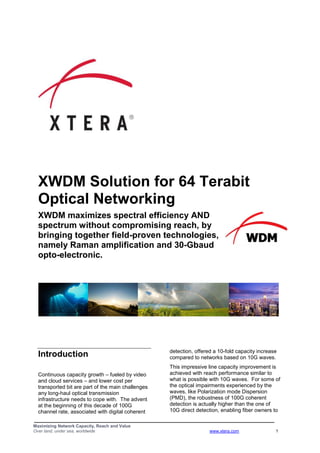
  • 1. Maximizing Network Capacity, Reach and Value Over land, under sea, worldwide www.xtera.com 1 XWDM Solution for 64 Terabit Optical Networking XWDM maximizes spectral efficiency AND spectrum without compromising reach, by bringing together field-proven technologies, namely Raman amplification and 30-Gbaud opto-electronic. Introduction Continuous capacity growth – fueled by video and cloud services – and lower cost per transported bit are part of the main challenges any long-haul optical transmission infrastructure needs to cope with. The advent at the beginning of this decade of 100G channel rate, associated with digital coherent detection, offered a 10-fold capacity increase compared to networks based on 10G waves. This impressive line capacity improvement is achieved with reach performance similar to what is possible with 10G waves. For some of the optical impairments experienced by the waves, like Polarization mode Dispersion (PMD), the robustness of 100G coherent detection is actually higher than the one of 10G direct detection, enabling fiber owners to
  • 2. Maximizing Network Capacity, Reach and Value Over land, under sea, worldwide www.xtera.com 2 monetize their aged assets, like, e.g., old fibers with high PMD figures. As 100G volume production starts, the cost per 10G equivalent is becoming lower with 100G waves than 10G waves. Although 100G technology is quite young (for the sake of comparison, 10G technology is 14-year old and will be still here within the next several years), some players of the optical telecommunication industry are already pushing for higher channel rates. The objective of this white paper is to review the current state of the art and possible options for the next steps toward higher-capacity optical networking. This white paper will also expose Xtera’s vision and approach for enabling higher-capacity, longer-reach optical networking using available technologies under the umbrella of Xtera’s XWDM solution. Technical Enablers of 100G Networks 100G Channel Rate Today’s 100G technology makes use of the PM-QPSK modulation format with coherent detection (PM: Polarization Multiplexing, QPSK: Quadrature Phase Shift Keying). 100G data rate is not achieved by modulating a single optical carrier using 100G binary modulation format: this would require opto- electronics operating at the rate of 100 binary symbols per second, so at the rate of 100 Gbaud – baud is the unit of symbol rate. Such opto-electronics speed is not available today for commercial purpose. The basic principle of PM-QPSK modulation format trades speed for parallelism at the expense of added complexity, as illustrated in Figure 1. Figure 1: Principle of PM-QPSK modulation format. First, two independent orthogonal states of optical polarization, at the very same optical frequency (because delivered by the same single laser source), are modulated. The polarization multiplexing halves the data rate, halves the spectral width, but doubles the count of components. The next parallelism step encodes the data to be transported not into 2 states like in any binary modulation format, but into 4-phase states. Consequently, a single phase symbol transports 2 bits of data. The quadrature phase shift keying halves the symbol rate compared to the binary phase shift keying. It also halves the spectral width but doubles the count of components. By following this approach, the speed of opto- electronics components needs to be only 25 Gbaud to transmit and receive a 100-Gbit/s signal. This 25-Gbaud symbol rate is much more robust in the face of fiber link impairments than a 100-Gbaud symbol rate would. Practically speaking, the line rate of the 100G PM-QPSK signal is closer to 120 Gbit/s than 100 Gbit/s because of the overhead added to the client data frame in order to accommodate OTN mapping as well as the overhead for forward error correction
  • 3. Maximizing Network Capacity, Reach and Value Over land, under sea, worldwide www.xtera.com 3 encoding. 100G PM-QPSK signals actually require approximately 30-Gbaud opto- electronics components. Figure 2 shows a typical implementation of a 100G digital coherent receiver with different stages: optical polarization splitting, mixing with an optical local oscillator, QPSK detection, optical impairments compensation and soft- decision forward error correction. Figure 2: Typical implementation of a 100G digital coherent receiver. Soft-Decision Forward Error Correction (SD-FEC) Until very recently, all of the correction codes that were used in high-speed optical transmission systems apply correction after the receiver has produced a one or zero based on whether the signal is above or below a given threshold value. It is easy to calculate the gain for a perfect code of this type. The number of errors that can be corrected depends on the number of different parity checks that are performed. Increasing the number of checks adds to the overhead, but Figure 3 shows that increasing the overhead (and thus the complexity) of the code adds only small improvements. The squares show examples of “hard-decision” codes that are utilized. Increasing the overhead also has the undesirable effect of increasing the line-rate and the spectral width of the signal. A potential solution employs "soft-decision" correction, where the receiver no longer produces a stream of binary digits. Instead a very high speed Analog to Digital Converter (ADC) produces a multi-bit signal that gives the amplitude of the detected signal. This helps because a signal close to the decision threshold is more likely to be on the "wrong" side than one that is distant. With this extra information, and using appropriate coding and decoding, it is possible in theory to produce results 3 dB better than the binary process. Although the decoding process is extremely complex and requires ultra-high speed electronics, soft-decision solutions for 100G solutions offer significant advantages over binary hard-decision codes. Figure 3: FEC gain vs. overhead. With the above techniques, Xtera achieves a net coding gain in the range of 1.5 to 2 dB. Xtera was the first optical networking equipment vendor to deploy 100G SD-FEC in a commercial network (in 2011 in a 22,000 km backbone network in Mexico). 5 FEC overhead (%) Hard-decision theoretical limit 10 15 20 25 30 5 6 7 8 9 10 11 Netcodinggain(dB) 12 13 Using 6 bit soft-decision decoding RS 239,255
  • 4. Maximizing Network Capacity, Reach and Value Over land, under sea, worldwide www.xtera.com 4 Figure 4: 100G interface cards with 10 client interfaces at 10G and soft-decision FEC. Performance of 100G Optical Networks The combination of PM-QPSK modulation, coherent detection, digital signal processing, and soft-decision forward error correction satisfies today’s capacity and reach needs. Using standard Erbium-Doped Fiber Amplifiers (EDFAs), line capacity of about 9 Tbit/s per fiber pair can be achieved on 2,000 km reach with no intermediate signal regeneration. 100G waves can propagate on standard G.652 fibers (which forms by far the largest portion of the terrestrial fiber infrastructures installed as of today) with no need for optical compensation of the fiber chromatic dispersion (the chromatic dispersion compensation is carried out in the electrical domain by the digital coherent receiver): this leads to the lowest latency that can be achieved in optical cable. Lastly the robustness to PMD exceeds 30 ps, i.e. 3 times larger than the tolerance with 10G direct detection! Current 100G coherent technology offers network operators the possibility to boost the capacity of their existing fiber asset with no significant reach reduction compared to what was achievable with 10G technology. Further incremental improvements of 100G coherent technology are still to come with more compact interface cards, lower power consumption, further cost reductions, more powerful digital signal processing and higher net coding gain from enhanced soft-decision forward error correction for improved transmission performance. Toward Higher Capacity Optical Networking: The Standard Approach Options for Increasing Line Capacity The key constraint is the limitation of the speed of opto-electronics devices, which is today and in the near future in the range of 30 Gbaud. Starting from this constraint, which imposes the upper limit of 30 giga (30 x 10 9 ) symbols per second, two main approaches are pursued in the telecom industry: the first approach is to increase the number of bits per symbol; the second one is to pack more densely the optical carriers within the available optical spectrum. Higher Number of Bits per Symbol Current 100G technology is based on Quadrature Phase Shift Keying (QPSK) modulation format. The phase of the optical signal is modulated and can take 4 different states (e.g. 45°, 135°, 225° and 315°), while
  • 5. Maximizing Network Capacity, Reach and Value Over land, under sea, worldwide www.xtera.com 5 the amplitude remains constant. Two bits per symbol are required to encode four phase states (e.g. 11 for 45°, 01 for 135°, 00 for 225° and 10 for 315°) as illustrated in Figure 5. Figure 5: QPSK and 16QAM constellation diagrams. With 16 Quadrature Amplitude Modulation (16QAM) modulation format, both the phase and the amplitude of the optical signal are modulated to give 16 different amplitude-phase combinations; 4 bits are then required to encode these 16 states (e.g. 0000 for phase- amplitude state # 1, 1111 for phase-amplitude state # 16). PM-16QAM modulation format doubles both the bit rate and the spectral efficiency (expressed in bit/s/Hz – where Hz is the bandwidth unit of the transmission medium) for the same symbol clock compared to PM-QPSK. Playing with 30-Gbaud symbol rate, PM-16QAM format leads to 200G data rate and a spectral efficiency of 4 bit/s/Hz. The counterpart of this higher number of states of the signal – or, equivalently, of bits per symbol – is the higher sensitivity on noise and other corruptions brought by propagation inside the optical fiber. Assuming EDFA amplifiers, 50-Ghz channel spacing, 0.2-dB fiber attenuation, about 80-km spans and 3-dB margin per span, 200G PM-16QAM can propagate on about 800 km before signal regeneration is required in order to ensure proper recovery of the data. This needs to be compared to 2,000-km reach performance for 100G PM-QPSK signals in the same span/fiber conditions. When longer spans or higher fiber loss are encountered in real network conditions, these reach figures are drastically reduced. Now that we have built a 200G optical carrier, two carriers can be combined to build a 400G optical channel (such a 400G signal is named DC PM-16QAM, where DC stands for Dual Carrier). An example of implementation is depicted in Figure 5. Figure 5: Example of implementation for a 400G channel made of two 200G carriers (DC PM-16QAM).
  • 6. Maximizing Network Capacity, Reach and Value Over land, under sea, worldwide www.xtera.com 6 The standard implementation employs 50-GHz spacing between the two carriers and is nothing more than the multiplexing of 200G waves on the standard 50-GHz grid. Compared to 100G waves, the line capacity is effectively doubled, from typically 8.8 to 17.6 Tbit/s, but the transmission reach is more than halved as discussed above. More Densely Packed Carriers Another way to further increase the spectral efficiency and the line capacity is to reduce the inter-carrier spacing, walking away from the standard 50-GHz spacing down to narrower spacing like, e.g., 37.5 GHz. Because of the presence of sidebands in the spectrum of any modulated digital signal, the narrower the carrier spacing is, the higher the interference level is. To effectively enable smaller carrier spacing, it may be necessary to shape the spectrum of the carriers at the transmit end in order to eliminate the side bands. Spectral shaping not only enables smaller spacing between carriers but also reduces the filtering distortion caused by, e.g., cascaded Reconfigurable Optical Add Drop Multiplexers (ROADMs). Driven by the interface card technology or the optical multiplexing-demultiplexing architecture of the optical equipment, carriers spaced by less than 50 GHz are often grouped into a channel whose capacity is a multiple of the carrier capacity. For example, a 1-Tbit/s channel can be built by combining ten 100G PM-QPSK carriers or five 200G DC PM- 16QAM carriers spaced 37.5 and 50 GHz apart, respectively, as depicted in Figure 6. Figure 6: Two ways to build a 1-Tbit/s channel. There are actually an infinite number of combinations to build multiple-carrier channels, playing with the capacity, spacing and number of carriers. The inter-carrier spacing can be reduced to increase further the spectral efficiency, at the expense of degraded reach performance. Assuming 100G PM-QPSK carriers, moving from 50- to 37.5-GHz spacing increases the line capacity by 1.1 dB (from 8.8 to 11.6 Tbit/s for EDFA-constrained link), but decreases in the same time the reach by 1.9 dB. Narrow inter-carrier spacing enables fatter but shorter pipes, with the net result of reducing the [Capacity x Reach] metric of the system. Combining More Bits per Symbol and Narrower Inter-Carrier Spacing Both approaches can be combined to reach a spectral efficiency in excess of 5 bit/s/Hz as illustrated in Figure 7. Figure 7: Spectral efficiency and all-optical reach for various carrier modulation and spacing strategies for EDFA-based systems. Figure 7 also clearly shows the dramatic decrease in all-optical reach that accompanies the increase in the spectral efficiency: when the spectral efficiency goes from 2 up to 5.3 bit/s/Hz, the reach goes downwards from 2,000 to about 400 km. Limitations of Traditional Approach Within the 30-Gbaud speed constraint for the symbol rate, there are some solutions to increase the line capacity of current 100G optical networking products. Today, the line capacity that is typically offered is
  • 7. Maximizing Network Capacity, Reach and Value Over land, under sea, worldwide www.xtera.com 7 88 x 100G = 8.8 Tbit/s. 200G PM-16QAM carriers spaced 37.5 GHz apart could lead to a line capacity of about 23 Tbit/s but with a reach limited to 400 km in very specific network conditions. If some spans are longer than 80 km or if some fiber portions attenuate the signals by more than 0.2 dB/km, the 400-km reach figure will significantly drop and be inappropriate for real-world backbone applications. EDFA amplification technology limits the [Capacity x Reach] performance in two ways:  The optical spectrum is limited to a maximum of 38 nm: packing more carriers means narrower spacing and stronger inter-carrier optical impairments inside the optical fiber.  EDFAs represent hot spots, boosting the signals power periodically along the optical links: such a power profile is conducive to nonlinearities within the line fiber at the beginning of each span. Although very powerful to compensate for linear degradations (like chromatic dispersion and PMD), the digital signal processing of coherent receiver is not yet effective in compensating for nonlinear degradations. Lastly, EDFA noise performance is not optimal, resulting in a significant noise accumulation along the optical path with multiple in-line amplifiers. This noise accumulation degrades the Optical Signal-to-Noise Ratio (OSNR) experienced by the optical channels and limits the [Capacity x Reach] metric. Raman Amplification to Unleash Line Capacity and Reach Amplifier Wish List Line equipment with wider optical spectrum is obviously one of the first requirements. Wider spectrum means more waves than can fit into the amplifier spectrum and/or larger spacing between carriers to reduce the amount of interference and nonlinearities between the carriers. Noise performance is also a key parameter for optical transport over long distances. Because the OSNR requirements are more stringent when the channel rate (driven by the number of symbols per seconds and the number of bits per symbol) increases, reducing the amount of optical noise generated by a string of optical amplifiers is critical for increasing the unregenerated reach. Another key item on the ideal amplifier wish list is the capability to limit the amount and efficiency of nonlinearities. As most of the terrestrial deployments happen on existing fiber infrastructures, installing less nonlinearity- sensitive fibers with, e.g., larger effective core area is not an option. Therefore an amplification technology that avoids “hot points” inside the line fiber between the ingress and egress points of the optical paths is of paramount importance. Benefits from Raman Amplification Raman amplification is an effective answer to meet these three key requirements:  Raman-based optical amplifiers offer up to with 100-nm bandwidth (such amplifiers were deployed by Xtera in as soon as 2004);  Superior noise performance of Raman-based optical amplifiers leads to higher OSNR performance at the output end of the optical path;  Distributed Raman amplification within the line fiber results in a lower peak-to- peak power excursion along the optical path, reducing the amount of nonlinearities. Another way to describe Raman amplification benefits is to consider two dimensions with respect to the direction of transmission in the line fiber. In the transversal dimension, Raman optical amplification offers a broader spectrum beyond the spectral bottleneck imposed by EDFA amplifiers. In the longitudinal direction, Raman optical amplification has the ability to extend reach thanks to better noise performance and distributed amplification within the line fiber
  • 8. Maximizing Network Capacity, Reach and Value Over land, under sea, worldwide www.xtera.com 8 (instead of being a purely passive transmission medium, some portions of the optical spans can provide the optical carriers with optical gain). Broader Spectrum with Raman Amplification Figure 8 is a simple way to illustrate the spectrum benefit offered by Raman optical amplification. Figure 8: Typical optical spectral and channel counts (assuming 50-GHz channel spacing) offered by different optical amplification technologies. The optical spectrum of EDFA amplifier typically ranges from 32 to 38 nm. Xtera’s EDFA supports a 37-nm spectrum width that enables the multiplexing of up to 93 channels spaced 50 GHz apart. When Raman pumping modules are added to an EDFA amplifier in order to build optical gain inside the line fiber, the resulting spectrum width cannot exceed the one of EDFA amplifier (like in the cascade of band-pass filters, the bandwidth of the combined filters is strongly governed by the narrowest bandwidth). To go beyond the conventional spectral band (C band) offered by EDFA amplifier, one needs to get rid of the spectral bottleneck imposed by Erbium ions in the EDFA approach and switch to another optical amplification technology. Raman optical amplification enables building optical from spectrum up to 100-nm width by combining several optical pump sources at different wavelengths as illustrated in Figure 9. Xtera has developed different flavors of Raman optical amplification:  Raman implementation: its 61-nm spectrum can accommodate up to 150 optical carriers assuming 50-GHz channel spacing;  Raman+ implementation: its extended 100-nm spectrum can support up to 240 optical carriers, spaced 50 GHz apart. Figure 9: Basic principle of Raman optical amplification. Extended Reach with Raman Amplification The higher the fiber attenuation, the more optical gain is required to compensate for the loss in the power of the transmitted signals. However, optical gain, like electronic gain, is achieved at the expense of noise added to the signals. As a result, the OSNR of the optical carriers is degraded by fiber loss and optical amplification. The optical signals cannot experience attenuation levels which are too elevated otherwise the data will be corrupted by the optical noise, with no way to properly
  • 9. Maximizing Network Capacity, Reach and Value Over land, under sea, worldwide www.xtera.com 9 recover their integrity at the output end of the optical link. The optical noise imposes a lower limit on the per wavelength power along the optical fiber. Nonlinearities in silica optical fiber are caused by the Kerr effect. The Kerr effect describes the dependency of the refractive index of the optical waveguide on the instantaneous optical intensity. The higher the signal power, the higher the nonlinearities and the subsequent distortions that are experienced by the optical signals. Nonlinearities impose an upper limit on the per wavelength power that can be launched into the optical fiber. Because of the upper limit for per channel power set by nonlinear effects and the lower limit imposed by minimal OSNR requirement, the per channel optical power profile must fit within some kind of “optical power tunnel” in order to guarantee data integrity along the optical fiber. Figure 10: “Optical power tunnel” for maintaining optical signal integrity. This “optical power tunnel” is illustrated above in Figure 10: as soon as the per channel power hits either the upper or lower limit, the quality of the data carried by the optical channel is irreparably impacted. Figure 11: Typical per channel optical power profile as a function of the transmission distance in chains of EDFA and Raman amplifiers
  • 10. Maximizing Network Capacity, Reach and Value Over land, under sea, worldwide www.xtera.com 10 The management of per channel power is quite different in an optical transmission system relying on Raman amplification. Here, the line fiber is not only a transmission medium bringing optical attenuation to the optical channels but also a gain medium because of the distributed Raman amplification effect occurring inside the line fiber when Raman pump waves are launched into the line fiber. In the backward Raman implementation, the Raman pumps are launched upstream from the repeater site into the preceding fiber span, in a counter direction compared to the direction of transmission for optical channels. In the forward Raman implementation, the Raman pumps are launched downstream, from the repeater site into the following fiber span, in the same direction as the direction of transmission for optical channels. Figure 11 above illustrates the evolution of the per channel optical power along a link made of several spans and in-line Raman amplifiers. The net result is a lower peak-to-peak power excursion along the optical path compared to the EDFA chain, keeping the optical signals away from noise and nonlinear impairments. Reach wise, the benefit offered by distributed Raman amplification is two-fold:  Possibility to design and implement all- optical links with ultra-long end-to-end reach because the degrading effects that accumulate with the transmission distance are mitigated: o Improvement of the link OSNR performance o Reduction in the amount of nonlinearities distorting the optical signals  Possibility to bridge longer spans than EDFA-based systems The second benefit (long span capabilities) is symbolized in Figure 11 by the span between in-line amplifiers E and F: distributed Raman amplification inside the line fiber not only limits the OSNR degradation and nonlinear impairments along the transmission but also enables longer spacing between sites E and F. In short, better noise performance and lower peak power inside the optical fiber are the two key features offered by distributed Raman amplification that enable both long end-to-end reach and long spans between adjacent sites. Achievements with Raman Amplification In the past years, and in real networks environments, Raman amplifications allowed the following 100G link implementations with Xtera’s Nu-Wave Optima TM optical networking platform:  1,300-km all-optical route including a 250-km / 60-dB span; with the common EDFA approach, the channels would have to be terminated at either end of this 250-km, 60-dB span, imposing costly regeneration sites;  2,500-km, 24-span all-optical route; this length represents the longest 100G all-optical link ever deployed in real field conditions, with practical fiber attenuation, standard margin per span for repair and non-uniform span lengths (up to 227 km) as found in real network environments;  7 Tbit/s per fiber pair on a 350-km / 65.5-dB unrepeatered link (with 34 x 100G recently demonstrated on a 436- km link). In its original configuration, Nu-Wave Optima TM platform supported line capacity of 15 Tbit/s, made of 150 carriers at 100G each. More recently Xtera conducted extensive lab and field trials, using the same Nu-Wave Optima TM platform, in order to confirm the value of Raman optical amplification for higher line rate with ultra-long-haul capabilities.
  • 11. Maximizing Network Capacity, Reach and Value Over land, under sea, worldwide www.xtera.com 11 XWDM Solution for Unparalleled Reach and Capacity Performance Drivers to XWDM Conventional optical networking products are typically built around EDFA amplification that presents several limitations as previously listed: far from optimal optical noise performance, generation of nonlinearities at the beginning of each fiber span and narrow optical spectrum. As a result, increase in line capacity by moving from 100G to 400G channel rate (made of, e.g., two carriers, each carrying 200G using PM-16QAM) and/or decreasing the channel spacing strongly reduces the reach. 16QAM modulation format with EDFA amplification will work only for a limited number of applications in the real world, being understood that backbone operators will not go to the expense of putting in intermediate signal regeneration to employ this technology. Regeneration sites represent many drawbacks for the operators, such as: high power consumption, large space requirements and points of lower reliability. Beyond these OpEx issues, regeneration sites are also very costly when the network capacity grows because interface cards must be deployed for each new wavelength put in service (contrary to an amplification site where all of the waves present in the line share the cost of the amplifier). Regeneration sites imply significantly higher incremental cost and longer lead time when placing new capacity into service compared to an optically-amplified link implementation. The incremental cost for added capacity is all the higher since the data rate supported by the optical wavelengths is high. For all these reasons, it is of the utmost importance to avoid or minimize the number of regeneration sites for long light paths in order to build a cost-effective optical network. XWDM Solution Bringing together current opto-electronics technology (offering 30-Gbaud symbol rate) and Raman optical amplification, XWDM is Xtera’s solution to enable 100G and Beyond 100G optical networking with ultra-long reach. Raman amplification, with better noise performance and smaller amount of nonlinearities generated in the line fiber compared EDFA amplification, typically enables a two-fold increase in the reach as illustrated by Figure 12. Figure 12: “All-optical reach as a function of modulation format for different optical amplification options. Additionally Raman amplification offers up to three-fold increase in the optical spectrum width, providing more room (up to 100 nm) for multiplexing optical carriers. Xtera developed two all-Raman implementations: Raman with 61-nm spectrum, and Raman+ with 100-nm spectrum. Figure 13: “[Capacity x Reach] metric as a function of modulation format and for different optical amplification options.
  • 12. Maximizing Network Capacity, Reach and Value Over land, under sea, worldwide www.xtera.com 12 Figure 13 represents the [Capacity x Reach] performance for different combinations of modulation formats and line equipment technology (EDFA, Raman or Raman+). For a given amplifier technology, [Capacity x Reach] metric is about constant, independently on the spectral efficiency. Raman amplification with 100-nm spectrum enables 6 times higher [Capacity x Reach] metric compared to EDFA amplification. XWDM can transmit 240 waves at 100G each (total of 24 Tbit/s) on more than 4,500 km with no need for intermediate regeneration. Using PM-16QAM modulation format and various inter-carrier spacings, XWDM can also transmit a line capacity of 48 Tbit/s and 64 Tbit/s on 2,000 and 1,500 km, respectively. Figure 14 summarizes the two key components of XWDM solution and the way they interplay to build up the combination of capacity and reach for optical transmission. Figure 14: XWDM components. The first XWDM component is the selector of modulation format and carrier spacing. Using 30-Gbaud opto-electronics, 100G, 400G or 1T channels can be built with the combination of 100G PM-QPSK or 200G PM-16QAM carriers. The inter-carrier spacing is an additional parameter that enables the setting of the spectral efficiency and thus the line capacity for a given line spectrum. The second XWDM component is the optical spectrum shaper. As soon as EDFA amplifiers are used in the line equipment, the spectrum is constrained by the spectral EDFA bottleneck (37 nm for Xtera’s equipment). The simple addition of Raman modules to extend the reach between spans cannot widen this optical spectrum. In addition to EDFA or hybrid EDFA/Raman amplification, Xtera offers two all-Raman implementations: Raman with 61- nm spectrum, and Raman+ with 100-nm spectrum. Hence Xtera’s Nu-Wave Optima TM optical networking platform offers the choice between three optical spectrum widths – 37, 61 and 100 nm – corresponding to 93, 150 and 240 channels spaced 50 GHz apart, respectively. Although sometimes considered in the past as an over-engineered solution for 10G networking, today the industry considers Raman optical amplification to be a critical enabler for efficient 100G and Beyond 100G long-haul networking in field conditions (including aged fibers, non-uniform span lengths, multiple optical distribution frames, connectors, and fiber repairs along the optical path). Unlike competitive offerings where integrating optical Raman amplifier with EDFA was an
  • 13. Maximizing Network Capacity, Reach and Value Over land, under sea, worldwide www.xtera.com 13 afterthought, Xtera designed its Nu-Wave Optima TM optical networking platform from the ground up to combine different optical amplification flavors, ranging from simple EDFA to all-distributed Raman amplification. One key concern in the design and development phases of Xtera’s Raman amplifiers was to offer equipment as simple, if not simpler, to operate as EDFA-based equipment. Xtera’s Raman amplifier sub- system has proved to offer high efficiency, excellent reliability and unparalleled reach- performance due to the high integration of the different optical amplification technologies. Xtera deployed in 2004 Raman amplifiers with 100nm spectrum; these amplifiers are still running today. More fundamentally, in information theory, the Shannon–Hartley theorem tells the maximum rate at which information can be transmitted over a communications channel of a specified bandwidth in the presence of noise. Optical spectrum and OSNR are the fundamentally limiting factors for optical communications. Raman amplification helps network designers increase network capacity thanks to its significantly better spectral and noise performances compared to EDFA amplification. Conclusion Combining current opto-electronics technology (the one utilized today to build 100G channels) and Raman optical amplification (as deployed by Xtera in the last decade), Xtera’s XWDM solution enables 100G and Beyond 100G optical networking with ultra-high capacity and ultra-long reach. XWDM solution was validated by commercial deployments and extensive lab and field trials, some of them in the Verizon network, using Xtera’s commercial optical networking Nu- Wave Optima TM platform. Xtera’s XWDM enables high spectral efficiency AND wide optical spectrum without compromising reach. Limited reach with 400G channels and EDFA amplifiers is a critical issue for backbone applications. XWDM offers 64T line capacity on more than 1,500 km in field conditions by combining 200G carriers and 100nm optical spectrum. Beyond the raw benefits in terms of capacity and reach, XWDM offers more linear optical propagation inside the line fiber, simplifying restoration rerouting in meshed configuration. XWDM also supports more channels for higher capacity headroom, broader spectrum for spectrum sharing applications, and lower incremental cost when new capacity is added due to the minimization of regeneration sites.
  • 14. Maximizing Network Capacity, Reach and Value Over land, under sea, worldwide www.xtera.com 14 Maximizing Network Capacity, Reach and Value Over land, under sea, worldwide Edition Date: December 2013 Version: 1.0