SlideShare a Scribd company logo
1 of 27
Introduction
Thapar University, Patiala Page 1
CHAPTER: 1
INTRODUCTION
1.1 GENERAL
Concrete is the man-made material which has the vastest utilization worldwide. This
fact leads to important problems regarding its design and preparation to finally obtain an
economic cost of the product on short and long time periods. The material has to be also
“friendly with the environment” during its fabrication process and also its aesthetical
appearance when it is used in the structures. Its success is when its raw materials that have a
large spreading into the world, the prices of raw materials that are low and the properties and
the performances of the concrete that confers it a large scale of application. Concrete’s
performances have continuously rise in order to accomplish the society needs. Many studies
have been made concerning the use of additives and super–plasticizers in the concrete by using
minimum water content for a good workability of a concrete. As a result of this, high
performance concretes developed having a superior durability.
Self-compacting concrete, as the name indicates, is a type of concrete that does not
require external or internal vibration for placing and compaction but it gets compacted under
its self-weight. It is able to flow under its own weight, completely filling formwork and
achieving full compaction, even in the presence of congested reinforcement. At the same time
it is cohesive enough to fill spaces of almost any size and shape without segregation or
bleeding. This makes SCC particularly useful wherever placing is difficult, such as in heavily
reinforced concrete members or in complicated formwork.
1.2 DEVELOPMENT OF SELF- COMPACTING CONCRETE
For several years beginning in 1983, the problem of the durability of concrete structures
was a major topic of interest in Japan. To make durable concrete structures, sufficient
compaction by skilled workers is required. However, the gradual reduction in the number of
skilled workers in Japan's construction industry has led to a similar reduction in the quality of
construction work. One solution for the achievement of durable concrete structures
independent of the quality of construction work is the employment of self-compacting concrete,
which can be compacted into every corner of a formwork, purely by means of its own weight
and without the need for vibrating compaction. The necessity of this type of concrete was
Introduction
Thapar University, Patiala Page 2
proposed by Professor Hajime Okamura in 1986. Studies to develop self-compacting concrete,
including a fundamental study on the workability of concrete, were carried out by Ozawa and
Maekawa at the University of Tokyo. SCC technology in Japan was based on using
conventional superplasticizers to create highly fluid concrete, while also using viscosity-
modifying agents (VMA) which increase plastic viscosity thus preventing segregation up to a
level of fluidity that would normally cause segregation. The prototype of self-compacting
concrete was first completed in 1988 using materials already on the market. The prototype
performed satisfactorily with regard to drying and hardening shrinkage, heat of hydration,
denseness after hardening, and other properties(Okamura and Ouchi , 2003). This concrete was
named “High Performance Concrete.” and was defined as follows at the three stages of
concrete:
(1) fresh: self-compactable
(2) early age: avoidance of initial defects
(3) hardened: protection against external factors
At almost the same time, “High Performance Concrete” was defined as a concrete with
high durability due to low water-cement ratio by Professor Aitcin. Since then, the term high
performance concrete has been used around the world to refer to high durability concrete.
Therefore, Okamura has changed the term for the proposed concrete to “Self-Compacting High
Performance Concrete.”
1.3 MECHANISM OF SELF-COMPACTING CONCRETE
Self-compactability can be largely affected by the characteristics of materials and the
mix proportion. A rational mix-design method for self-compacting concrete is necessary.
Okamura and Ozawa have proposed a simple mix-proportioning system assuming general
supply from ready-mixed concrete plants . The coarse and fine aggregate contents are fixed so
that self-compactability can be achieved easily by adjusting the water powder ratio and
superplasticizer dosage only. SCC requires a higher level of quality control than conventional
slump concrete. Okamura, Ozawa (2003) have employed the following methods to achieve
self-compactability:
 Limited aggregate content
 Low water-powder ratio
 Use of super plasticizer
Introduction
Thapar University, Patiala Page 3
Fig. 1.1: Necessity of Self- Compacting Concrete (Ouchi and Hibino, 2000)
The method for achieving self-compactability involves not only high deformability of paste
or mortar, but also resistance to segregation between coarse aggregate and mortar when the
concrete flows through the confined zone reinforcing bars.
The frequency of collision and contact between aggregate particles can increase as the
relative distance between the particles decreases and then internal stress can increase when
concrete is deformed, particularly near obstacles. Research has found that the energy required
for flowing is consumed by the increased internal stress, resulting in blockage of aggregate
particles. Limiting the coarse aggregate content, whose energy consumption is particularly
intense, to a level lower than normal is effective in avoiding this kind of blockage. Highly
viscous paste is also required to avoid the blockage of coarse aggregate when the concrete
flows through obstacles. When the concrete is deformed, paste with a high viscosity also
prevents localized increases in internal stress due the approach of coarse aggregate particles.
High deformability can be achieved only by the employment of a super-plasticizer, keeping the
water-powder ratio to a very low value.
Additionally, the paste or mortar has to deform well too. Contact and collision between
aggregates as well as the interparticle friction increase with the decreases in relative distance
between aggregates particles in the concrete mix, resulting in the blockage of aggregate
particles. Limiting coarse aggregate volume increases inter-particle separation and reduces the
inter-particle friction and collisions resulting in minimization of the blockage leading to
improvement in passing ability.
Skill of
Workersl
Self – Compacting
Concrete
Durable Concrete
Structure
Decreas In the
Introduction
Thapar University, Patiala Page 4
Fig. 1.2: The schematic composition of SCC (Brouwers and Radix, 2005)
The increase of paste volume with emphasis to low water powder ratio (w/p) in
presence of compatible chemical admixtures further strengthens the fluidity and helps in
attaining homogeneity. Adequate homogeneity improves viscosity of the mix, which in turn
enhances the segregation resistance. An optimum balance between fluidity and viscosity is the
key to achieve efficient self-compacting characteristics of the concrete mix at fresh state. In
SCC, the powder contains binder component consisting of ordinary Portland cement (OPC),
mineral admixtures like fly ash along with/ without filler material like limestone powder,
dolomite etc. To achieve moderate plastic viscosity and low yield value, multiple chemical
admixtures are required. Special chemical admixture like viscosity modifier admixture (VMA)
is used for controlling the viscosity of the mix and super plasticizer for lowering the yield
stress. In addition, the characteristics of fine and coarse aggregates play very important role on
the yield stress of the mix.
Fig. 1.3: Mechanism for achieving self-compactability. (Okamura and Ouchi, 2003)
Introduction
Thapar University, Patiala Page 5
Fig. 1.4: Methods to achieve self-compactability of fresh concrete
(Okamura and Ouchi, 2003)
1.4 PROPERTIES AND TESTS OF SELF-COMPACTING CONCRETE
Fresh SCC must possess at required levels the following key properties related to
workability:
Filling ability: This is the ability of the SCC to flow, spread and fill into all spaces within the
formwork under its own weight.
Passing ability: This is the ability of the SCC to flow through tight openings such as spaces
between steel reinforcing bars, under its own weight without blocking them.
Resistance to segregation: The SCC must meet the required levels of properties and its
composition remains uniform throughout the process of transport and placing that is keeps the
sand and aggregate in suspension.
Introduction
Thapar University, Patiala Page 6
Fig.1.5: Basic workability requirements for successful casting of SCC (Khayat, 1999)
1.4.1 PROPERTIES
Some of the important tests conducted on fresh SCC to evaluate its workability are briefly
explained and summarized below in a table:
Table 1.1: Test methods to evaluate the workability properties of SCC
(EFNARC, 2002).
Property Test Methods
Laboratory
(Mix Design)
Field
(Quality Control)
Filling Ability Slump Flow Test
T50 Flow Test
V-Funnel Test
Orimet Test
Slump Flow Test
T50 Flow Test
V-Funnel Test
Orimet Test
Passing Ability L-Box Test
U-Box Test
Fill Box Test
J-Ring Test
Segregation Resistance GTM Test
V-Funnel At T5min
GTM Test
V-Funnel At T5mins
U-type test: Of the many testing methods used for evaluating self-compact ability, the U-type
Introduction
Thapar University, Patiala Page 7
test (Fig. 1.6) proposed by the Taisei group is the most appropriate, due to the small amount of
concrete used, compared to others (Ferraris, 1999). This test is used to measure the filling
ability of SCC. The apparatus consists of a vessel that is divided by a middle wall into two
compartments. It provides a good direct assessment of passing ability.
For conducting the U-box test, one of the compartments of the apparatus is filled with
the concrete sample and filled concrete is left to stand for 1 minute. Then the sliding gate is
lifted to allow the concrete to flow out into the other compartment. After the concrete comes
to rest, the height of the concrete in the compartment that has been filled is measured in two
places and the mean height (H1) is calculated. Also the height in the other compartment (H2)
is measured. The filling height is then calculated as H1- H2. The whole test has to be performed
within 5 minutes. If the concrete flows as freely as water, at rest it will be horizontal, so H1-
H2 = 0. Therefore, the nearer this test value, that is, the filling height', is zero, the better the
flow and passing ability of SCC (EFNARC, 2002).
Fig. 1.6: U-type test (EFNARC, 2002)
Slump Flow test: The slump flow test is used to assess the horizontal free flow of SCC in the
absence of obstructions. The basic equipment used is the same as for the conventional Slump
test. The test method differs from the conventional one by the fact that the concrete sample
placed into the mold is not rodded and when the slump cone is removed the sample collapses
Introduction
Thapar University, Patiala Page 8
(Ferraris, 1999). The diameter of the spread of the sample is measured, that is a horizontal
distance is determined as opposed to the vertical distance in the conventional Slump test. The
Slump Flow test can give an indication as to the consistency, filling ability and workability of
SCC. The SCC is assumed of having a good filling ability and consistency if the diameter of
the spread reaches values between 650mm to 800mm (EFNARC, 2002).
Fig. 1.7: Slump flow test (Zhimin et al., 2008)
Orimet test: The test is based on the principle of an orifice rheometer applied to fresh concrete
(Bartos, 2000). The test involves recording of time that it takes for a concrete sample to flow
out from a vertical casting pipe through an interchangeable orifice attached at its lower end.
The shorter the Flow-Time, the higher is the filling ability of the fresh mix. The Orimet test
also shows potential as a means of assessment of resistance to segregation on a site.
L-Box test: This method uses a test apparatus comprising of a vertical section and a horizontal
trough into which the concrete is allowed to flow on the release of a trap door from the vertical
section passing through reinforcing bars placed at the intersection of the two areas of the
apparatus (Dietz et al., 2000). The time that it takes the concrete to flow a distance of 200mm
and 400mm into the horizontal section is measured, as is the height of the concrete at both ends
of the apparatus (H1 & H2). The L-Box test can give an indication as to the filling ability and
passing ability.
Introduction
Thapar University, Patiala Page 9
Fig. 1.8: Schematic of L-box (Grdic et al., 2010).
Orimet/J-Ring combination test: This recently developed test involves the J-Ring being
placed centrally below the orifice of the Orimet apparatus, allowing the discharged mix to fall
into it and flow outwards (Bartos, 2000). The Orimet time is recorded as in the conventional
Orimet test, along with the diameter of the concrete spread and the height of the concrete within
the J-Ring. The more dynamic flow of concrete in this test simulates better the behaviour of a
SCCmix when placed in practice compared with the Slump-Flow variation. The Orimet/J-Ring
combination test will be used in the future as a method of assessing filling ability, passing
ability and resistance to segregation (Bartos, 2000).
Fig: 1.9 Orimet test (EFNARC, 2002)
Introduction
Thapar University, Patiala Page 10
V-funnel test: Viscosity of the self-compacting concrete is obtained by using a V-funnel
apparatus, which has certain dimensions (Fig. 1.10), in order for a given amount of concrete to
pass through an orifice (Dietz et al., 2000).
The amount of concrete needed is 12 litres and the maximum aggregate diameter is 20 mm.
The time for the amount of concrete to flow through the orifice is being measured. If the
concrete starts moving through the orifice, it means that the stress is higher than the yield stress;
therefore, this test measures a value that is related to the viscosity. If the concrete does not
move, it shows that the yield stress is greater than the weight of the volume used.
Fig 1.10: V-funnel (Dietz et al., 2000)
GTM Segregation test: This is a very recent test measuring the separation of aggregate in a
sample after a period of time and wet sieving. The test has a potential for detection of tendency
to segregate (Dehn et al., 2000). It completes the tests (Slump-Flow, L-Box, etc.) carried out
to estimate the filling ability in free or shut-in environment (that is with some "wall-effect") by
specifying the segregation resistance. This test can be used in laboratory when developing a
concrete mix, as well as on site, when carrying out suitability tests on the delivered concrete.
Slump Flow/J-Ring combination test: This test (Fig. 1.11) involves the slump cone being
placed inside a 300mm diameter steel ring attached to vertical reinforcing bars at appropriate
spacing (the J-Ring itself) (Kosmatka et al., 2002). The number of bars has to be adjusted
depending on the maximum size aggregate in the SCC mix. Like in the Slump Flow test, the
diameter of the spread and the T-50 time are recorded for the evaluation of SCC viscosity. The
Slump Flow/J-Ring combination test is an improvement upon the Slump Flow test on its own
Introduction
Thapar University, Patiala Page 11
as it aims to assess also the passing ability of the fresh mix. In this respect, the SCC has to pass
through the reinforcing bars without separation of paste and coarse aggregate.
Fig. 1.11 : Slump Flow/J-Ring combination test (Kosmatka et al., 2002)
Typical acceptance criteria for SCC with a maximum aggregate size of up to 20 mm are
presented in Table 1.2.
Table 1.2 : Acceptance criteria for Self-compacting Concrete (EFNARC, 2002)
Method Unit
Minimum
Value
Maximum
Value
Slump flow Mm 650 800
J –Ring Mm 0 10
V- Funnel Sec 6 12
L-Box (H2/H1) 0,8 1,0
U- Box (H2-H1)mm 0 30
Orimet Sec O 5
Fill Box % 90 100
1.5 ADVANTAGES AND DISADVANTAGES OF SELF-COMPACTING CONCRETE
1.5.1 ADVANTAGES
 No vibration of fresh concrete is necessary during placement into forms.
 Placement of concrete is easier.
Introduction
Thapar University, Patiala Page 12
 Faster and more efficient placement of fresh concrete is achieved. Total concreting time
is reduced.
 Energy consumption is reduced.
 Required number of workers on construction site is reduced.
 Safer and healthier working environment is obtained.
 High quality of placed concrete is achieved, regardless the skill of the workers.
 Good bond between concrete and reinforcement is obtained, even in congested
reinforcement.
 High quality of concrete surface finish is obtained with no need for subsequent repair.
 Improved form surface finish and reduced need to repair defects such as bug holes and
honeycombing.
 Improved ability of concrete to flow into intricate spaces and between congested
reinforcement.
 Reduced construction costs due to reduced labour costs and reduced equipment
purchase and maintenance costs.
 Increased construction speed due to fewer construction tasks.
 Faster unloading of ready mixed concrete trucks.
 Improved working conditions with fewer accidents due to elimination of vibrators.
 Improved durability and strength of the hardened concrete in some cases.
 Reduced noise generated by vibrators.
1.5.2 DISADVANTAGES
 Increased material costs, especially for admixtures and cementitious materials.
 Increased formwork costs due to possibly higher formwork pressures and to prevent
leakage.
 Increased technical expertise required to develop and control mixtures.
 Increased variability in properties, especially workability.
 Increased quality control requirements.
 Reduced quality of hardened properties in some cases possibly including modulus of
 Elasticity and dimensional stability—due to factors such as high paste volumes or finer
combined aggregate grading.
 Delayed setting time in some cases due to the use of admixtures.
 Requires more trial batches at laboratory as well as at plants.
Introduction
Thapar University, Patiala Page 13
 Increased risk and uncertainty associated with the use of a new product.
1.6 APPLICATIONS OF SELF-COMPACTING CONCRETE
SCC technology originated in Japan in the early 1980s, arising out of durability
concerns due to poor compaction on the job site. Use of SCC quickly became widespread in
Japan, especially since the government implemented a plan to use SCC for 50% of all concrete
jobs by 2003( FrancesYang,2004 ). It then spread to Europe in the 1990’s after invention of
polycarboxylate super plasticizers. In the UK, The Concrete Society has issued official
measures to expand the use of SCC as a means of replacing vibratory compaction. In the US
and Canada, SCC technology is available mostly in the form of proprietary concrete mixes
from ready-mix producer subsidiaries of cement manufacturers such as Lafarge and Lehigh. It
is also available as specialized admixtures combining super plasticizer and viscosity modifiers.
Given how important maintaining mix quality of SCC is for its successful performance, using
SCC demands increased attention and skill. In particular, superplasticizer dramatically
increases the sensitivity of the mix to water. This allows little room for error in mix
proportioning, which can become problematic in-field when weather and timing cannot always
be controlled by the contractor. In light of this, most applications of SCC in the US have been
limited to precast construction due to tighter quality control ensured in-plant compared to in-
field. However, the industry has shown eagerness to expand its use. Whereas in 2000, only
about 10% of the precast industry had tried SCC, by 2003, the number jumped to almost 90%,
of which 40% used it on a regular basis.
Some notable projects have utilized SCC in Canada. One is the Toronto International
Airport, where concrete had to be pumped upwards from the ground to form 101-foot tall
columns. Another project in Vancouver, B.C used SCC so little patching would be required for
highly visible, outrigger columns. In Asia, SCC was used for a monolithic foundation mat in
Singapore where the concrete needed to reach massive dimensions in a short amount of time.
In the US, a high-strength SCC was imperative for constructing tightly reinforced elements
poured in below-freezing weather for the 68-story Trump Tower in New York City.SCC has
also shown successful application for residential projects, such as homes for Habitat for
Humanity in the Houston area. Some of the structures built with self compacting concrete are
Burj Dubai , Arlanda airport control tower Stockholm, Sweden, National Museum of 21st
Century in Rome , Italy.
Introduction
Thapar University, Patiala Page 14
( Ouchi et al., 2003 ) A typical application example of Self-compacting concrete is the two
anchorages of Akashi-Kaikyo (Straits) Bridge opened in April 1998, a suspension bridge with
the longest span in the world (1,991 meters) . The volume of the cast concrete in the two
ahchorages amounted to 290,000 m3. A new construction system, which makes full use of the
performance of self -compacting concrete, was introduced for this. The concrete was mixed at
the batcher plant beside the site, and was the pumped out of the plant. It was transported 200
meters through pipes to the casting site, where the pipes were arranged in rows 3 to 5 meters
apart. The concrete was cast from gate valves located at 5 meter intervals along the pipes. These
valves were automatically controlled so that a surface level of the cast concrete could be
maintained. In the final analysis, the use of self compacting concrete shortened the anchorage
construction period by 20%, from 2.5 to 2 years. Self-compacting concrete was used for the
wall of a large LNG tank belonging to the Osaka Gas Company, whose concrete casting was
completed in June 1998 . The volume of the self-compacting concrete used in the tank
amounted to 12,000 m3.
The Ritto Bridge is a PC extra-dosed bridge with corrugated steel webs on the New
Meishin Expressway in Japan . The highest pier is 65-meter high. High strength concrete and
reinforcements, of which specified compressive strength and yield strength are 50 MPa and
685 MPa respectively, were applied to the construction of the pier to meet the earthquake
resistance. Arrangement of reinforcement was very dense; therefore SCC was chosen to obtain
good workability for the pier construction.
The Sodra Lanken Project (SL) is the largest infrastructure project in Sweden. The
overall cost of the SL is estimated to around 800 million USD. The SL will provide a six
kilometre four lane west - east link in the southern parts of Stockholm. The SL project includes
seven major junctions, with bridges, earth retention walls, tunnel entrances and concrete box
tunnels. The overall length of the rock tunnels are16.6 kilometres. They are partly lined with
concrete. The concrete volume used in the project amounts 225,000 cubic meters. The duration
of the SL project is estimated to last 6 years (1998 - 2004). The experiences with SCC are
generally good. SCC has primarily been used in connection with constructions difficult to
compact by normal vibration and high demands on aesthetics, for examples, in concrete rock
lining, underground installation structures and rock tunnel entrances, retention walls with
negative inclination and relief structures.
In India Delhi Metro Project have used SCCin large scale for dome construction, tunnel
lining , column casting. Hindustan Construction Company have also carried out considerable
studies on the use of High Volume Fly Ash self compacting concrete for domes walls in turbine
Introduction
Thapar University, Patiala Page 15
building in Rajasthan Power Project ,and Concrete for piers in Bandra Worli Sea Link
Projects.At Tarapur Atomic Power Project SCC was used for the construction of three walls of
a pump house .The height of the wall was 14.4 m and it was done in 5 pours.At Kaiga Nuclear
Power Project (Karnataka) SCC of characteristic strength 30 MPa was used in the two Mock
up structures one being heavily reinforced column with two beams passing through it and the
other being a thin wall (140mm thick).
1.7 LIMITATIONS OF SELF-COMPACTING CONCRETE
1.7.1 SCC PRODUCTION
 Production of SCC requires more experience and care than the conventional vibrated
concrete. The plant personnel would need training and experience to successfully
produce and handle SCC. In the beginning, it may be necessary to carry out more tests
than usual to learn how to handle SCC and gain the experience.
 Before any SCC is produced at the plant and used at the job site, the mix must be
properly designed and tested to assure compliance with the project specifications. The
ingredients and the equipment used in developing the mix and testing should be the
same ingredients and equipment to be used in the final mix for the project.
 Most common concrete mixers can be used for producing SCC. However, the mixing
time may be longer than that for the conventional vibrated concrete. SCC is more
sensitive to the total water content in the mix. It is necessary to take into account the
moisture/water content in the aggregates and the admixtures before adding the
remaining water in the mix. The mixer must be clean and moist, and contains no free
water.
 Admixtures for the SCC may be added at the plant or at the site. There is cost benefit
in adding the admixtures at the site. Conventional ready-mix concrete can be bought at
a lower cost than the cost of SCC bought from a ready-mix supplier.
1.7.2 TRANSPORTATION
 The truck drivers should be given oral and written instructions for handling SCC. The
truck drivers must check the concrete drum before filling with SCC to make sure that
the drum is clean and moist, but with no free water. Extra care must be taken for long
Introduction
Thapar University, Patiala Page 16
deliveries. In addition to the usual information, the delivery note should show the
following information:
 Slump flow - target value and acceptable range.
 Production time - time when it was produced.
 Instruction for adding admixtures at the site, if allowed.
 The truck drivers should not be allowed to add water and/or admixtures during transit.
1.7.3 FORM SYSTEM
 All commonly used form materials are suitable for SCC. For surface quality of SCC,
wood is better than plywood, and plywood is better than steel. More pores seem to form
on the surface when the form skin is colder than the SCC. During cold weather
placement of SCC, it may be necessary to insulate the formwork to maintain
temperature and normal setting time. SCC is more sensitive to temperature during the
hardening process than the conventional vibrated concrete.
 Due to the cohesiveness of SCC, the formwork does not need to be tighter than that for
conventional vibrated concrete.
 Higher form pressures than normal were not observed even at high rate of concrete
placement. However, it is recommended that the formwork be designed for hydrostatic
pressure, unless testing has shown otherwise.
1.7.4 CASTING ON SITE
 A pre-SCCplacement meeting with all personnel involved in the SCCplacement would
be beneficial. The SCC placement plan, including QC/QA, and the roles and
responsibilities of the field personnel should be explained and understood.
 In addition to the normal testing, the slump flow, T50 and L-box tests are useful to
check SCC at the job site before placement.
 SCC can flow horizontally a distance of 15 to 20m without segregation. A well-
designed SCC may have a free fall of as much as 8m without segregation. However, it
is recommended that the distance of horizontal flow be limited to 10m and the vertical
free fall distance be limited to 5m.
 For deck slab of a bridge, it would be difficult for the SCC to flow too far. This could
be handled by designing an SCC with a lower slump flow. With a lower slump flow, a
bridge deck with a slope of 2% could also be accomplished.
Introduction
Thapar University, Patiala Page 17
 If an SCC placement is interrupted and the concrete has started to harden, it would be
necessary to .wake up. the placed concrete by striking a stick or board into the concrete
several times before starting the placement again.
 SCC takes some time before the hardening starts, especially during cold weather
conditions. When it starts to harden, the process is very rapid, which can cause problems
in levelling and treating large surface areas.
1.7.5 SURFACE FINISHING AND CURING
 Finishing and curing of SCC can follow the good practices of super plasticized high
performance concrete. Surface of SCC should be roughly levelled to the specified
dimensions, and the final finishing applied as necessary before the concrete hardens.
 SCC tends to dry faster than conventional vibrated concrete, because there is little or
no bleeding water at the surface. SCC should be cured as soon as practicable after
placement to prevent surface shrinkage cracking.
1.7.6 COLD JOINT
 When placing a new layer of SCC on old SCC, the bond between the old and new SCC
is equal to or better than in the case of conventional vibrated concrete. Normal vibration
will not destroy the concrete, such as in the case of placing conventional vibrated
concrete on fresh SCC. This may be necessary when the surface slope is greater than
practicable for SCC (Ouchi et al., 2003).
1.8 WORLD-WIDE CURRENT SITUATION OF SELF-COMPACTING CONCRETE
Self-compacting concrete has already been used in several countries. In Japan, major
construction projects included the use of SCC in the late ’90s. Today, in Japan, efforts are being
made to free SCC of the “special concrete” label and integrate it into day-to-day concrete
industry production. Currently, the percentage of self-compacting concrete in annual product
of ready-mixed concrete (RMC), as well as precast concrete (PC), in Japan is around 1.2% and
0.5% of concrete products. In the United States, the precast industry is also leading SCC
technology implementation through the Precast/Pre-stressed Concrete Institute (PCI) which
has done some research on the use of SCC in precast/pre-stressed concretes starting with 1999.
It is estimated that the daily production of SCC in the precast/pre-stressed industry in the United
Introduction
Thapar University, Patiala Page 18
States will be 8000 m3 in the first quarter of 2003 (around 1% of the annual ready-mix
concrete). Furthermore, several state departments of transportation in the United States (23
according to a recent survey).
Bartos, (2000) are already involved in the study of SCC. With such a high level of
interest from the construction industry, as well as manufacturers of this new concrete, the use
of SCC should grow at a tremendous rate in the next few years in the United States. However,
even if it is made from the same constituents the industry has used for years, the whole process,
from mix design to placing practices, including quality control procedures, needs to be
reviewed and adapted in order for this new technology to be applied properly. Research
regarding the self-compacting concrete was also carried out in Canada, few years after the
concept was introduced in Japan. Institute for Research in Construction, Canadian Precast/Pre-
stressed Concrete Institute, CONMET-ICON, and ISIS are some of the bodies which studied
various aspects of the new technology. The introduction of the SCC in Europe is largely
connected with the activities of the international association RILEM, France, particularly of its
Technical Committee TC145-WSM on “Workability of Fresh Special Concrete Mixes” (Dhir
and Dyer, 1999). The TC145-WSM was founded in 1992 and immediately attracted expert
memberships from all over the world. The aim was to look at the production stage of a number
of “special” concretes and identify workability parameters and other characteristics of the
mixes in their fresh state that governed the reliable and economical achievement of the
“special” or “high-performance” parameters the concretes offered. As the importance of the
SCC became widely recognized, other European countries, Germany, Sweden, UK, Denmark,
Netherlands, Norway, Finland, etc., have decided to keep up with the developments in this
area. For example, in Sweden, the SCC market share was at five percent in RMC and PC in
2002, and was expected to double in 2003. Housing and tunnelling, as well as bridge
construction for the Swedish National Road Administration were the main areas of use for
SCC. In the Netherlands and Germany, the precast industry is mainly driving the development
of SCC, with an expected eight percent of market share in 2003 in Netherlands. Today, self-
compacting concrete is being studied worldwide, with as per presented at almost every
concrete-related conference, but until now - year 2003 - there is no universally adopted
standardized test method for evaluation of self-compatibility of this concrete.
In India ,during the last few years ,attempts were made in the laboratories and in the
field to develop and use SCC. Some pioneering efforts have been made in Delhi Metro projects
in association with L&T and MBT .Nuclear Power Corporation , Gammon India, Hindustan
Construction Company have made large scale laboratory trials .Laboratory studies conducted
Introduction
Thapar University, Patiala Page 19
at SERC(Structural engineering research centre) Chennai, Indian Institute of Technology at
Madras, Roorkee and other places have given enough inputs and confidence to adopt SCC in
India. Of all the places Delhi Metro project have used SCC in large scale for dome construction,
tunnel lining, column casting.( Sood et al. 2009 )In India, the development of concrete
possessing self compacting properties is still very much in its infancy.During the last couple of
years, few attempts were made using European Guidelines for testing SCC in the laboratories
and in the field. SCC was used by Nuclear Power Corporation of India Ltd. at Tarapur, Kaiga
and Rajasthan Atomic Power Project (RAPP). Some pioneering efforts have been made in
Delhi Metro Project. In all the above investigations European standards were followed for
determining rheological properties of Self compacting concrete.
Today, self-compacting concrete is being studied worldwide, with papers presented at
almost every concrete-related conference, but until now there is no universally adopted
standardized test method for evaluation of self-compact ability of this concrete. Currently, the
use of self-compacting concrete is being rapidly adopted in many countries. The use of self-
compacting concrete should overcome concrete placement problems associated with the
concrete construction industry. However, there still is a need for conducting more research and
development work for the measurement and standardization of the methods for the evaluation
of the self-compacting characteristics of SCC.
1.9 NEED FOR THIS RESEARCH
There are many situations in today’s construction market that make SCCan interesting
alternative to conventional slump concrete. In general, cost savings and/or performance
enhancement tend to be the driving forces behind the added value of SCC. Contractors,
producers and owners are under great pressure to produce better quality construction at lower
costs of labour, materials and equipment. They are also faced with tougher environmental and
safety regulations, and increased insurance costs. The economic benefits of a less intensive
construction environment results in labour savings, time savings from higher productivity, and
greater flexibility of design. SCC offers some help in all of the following areas. The main
barrier to the increased use of SCC seems to be the lack of experience of the process, and the
lack of published guidance, codes and specifications. This situation will improve, however, as
experience and knowledge increases and each country begins to produce its own guidance and
specifications for the production of SCC with local marginal aggregates and the harsh
Introduction
Thapar University, Patiala Page 20
environmental conditions prevailing in the region. Therefore, there is a need to conduct studies
on SCC.
1.10 FOUNDRY SAND
A foundry produces metal castings by pouring molten metal into a preformed mould to
yield the resulting hardened cast. The metal casts include iron and steel from the ferrous family
and aluminium, copper, brass and bronze from non-ferrous family (Siddique, 2008). Foundry
sand is high quality silica sand used as a moulding material by ferrous and non-ferrous metal
casting industries. It can be reused several times in foundries but, after a certain period, cannot
be used further and becomes waste material, referred to as used or spent foundry sand (UFS or
SFS). The majority of spent moulding sands are classified as nonhazardous waste (that is not
corrosive, ignitable, reactive or toxic) (Siddique and Noumowe, 2008).Foundries use high
quality size-specific silica sands for use in their moulding and casting operations. The raw sand
is normally of a higher quality than the typical bank run or natural sands used in fill construction
sites. In the casting process, moulding sands are recycled and reused multiple times.
Eventually, however, the recycled sand degrades to the point that it can no longer be reused in
the casting process. When it is not possible to further reuse sand in the foundry, it is removed
from the foundry and is termed as spent foundry sand. The physical and chemical
characteristics of foundry sand will depend in great part on the type of casting process and the
industry sector from which it originates. In a recent study, (Siddique et al. 2009) reported that
in the United States alone, up to 10 million tons of foundry sand are discarded annually and are
available for recycling. Foundries purchase new, virgin sand to make casting moulds and the
sand is reused numerous times within the foundry. However, heat and mechanical abrasion
eventually render the sand unsuitable for use in casting moulds, and a portion of the sand is
continuously removed and replaced with virgin sand. The spent foundry sand, that is, the sand
that is removed, is either recycled in a non-foundry application or land filled.
1.11 PRODUCTION OF FOUNDRY INDUSTRY IN INDIA AND WORLD
There are about 35,000 foundries in the world with annual production of 90 million
tonnes. In terms of number of foundries China has the highest score (9374), followed by India
(6000). The share of Iron foundries is the maximum that is almost 56%, followed by steel with
14% and then the non-ferrous ones with 30%. The growing environmental concerns and
Introduction
Thapar University, Patiala Page 21
globalization of economies have led to a closure of some 8000 foundries in Europe. These
countries have been contemplating to shift their business to the low labour cost centres that is,
the developing countries.
The impetus for foundry sector in India was given by the Jute industry in Bengal and
the cotton industry in Mumbai in late 19th century. The establishment of TISCO, Bengal Iron
Company and the IISCO led to some remarkable new uses of castings, in domestic as well as
industrial areas. India ranks second in the world based on the number of foundry units present
(4550 units) - after China – and fourth in terms of total production (7.8 million tonnes) (42nd
Census of World Casting Production – 2007). Apart from the registered 4550 units there are
several unregistered units, which according to various sources range approximately from 1500
to 5000 units. As per the IREDA- CII Report 2004, there are around 10,000 foundry units
present in India including registered and unregistered units. Considering that 4550 units are
registered, the total number of units unregistered is around 5450 units. As per estimation of
experts of the foundry sector, there are around 1500 unregistered foundry units that are
scattered across the country. This discrepancy in unregistered units is mainly due to the fact
that the 5450 units included all kinds of micro and small units engaged in castings. Whereas
the 1500 units data incorporates only those foundry units that are engaged in grey iron casting
and use conventional cupola and excludes those units that are too micro in nature and use
crucible for melting of metals. Also several foundry units had closed due to non compliance
with the pollution standard set by the government for example Howrah, Agra and nearby areas.
The foundry produces a wide variety of castings such as manhole covers, pipe and pipe fittings,
sanitary items, tube well body, metric weights, automobile components, railway parts, electric
motor, fan body etc. 90% of the castings produced are from the SSI sector. Most of these units
are situated in clusters, with cluster size ranging from 30- 500 units. (Bhimani et al. 2013)
1.12 TYPES OF FOUNDRY SAND
Classification of foundry sands depends upon the type of binder systems used in metal
casting. Generally two types of binder systems are used and based on that foundry sands are
classified as: clay-bonded systems (green sand) and chemically bonded systems. Both types of
sands are suitable for beneficial use but they have different physical and environmental
characteristics.(Siddique and Singh , 2011)
1.12.1 GREEN SAND
Introduction
Thapar University, Patiala Page 22
Clay-bonded (Green) sand is composed of naturally occurring materials which are
blended together; high quality silica sand (85–95%), bentonite clay (4–10%) as a binder, a
carbonaceous additive (2–10%) to improve the casting surface finish and water (2–5%). It is
black in colour due to carbon content. Green sand is the most commonly used moulding media
by foundries. The silica sand is the bulk medium that resists high temperatures while the
coating of clay binds the sand together. The water adds plasticity. The carbonaceous additives
prevent the “burn-on” or fusing of sand onto the casting surface. Green sands also contain trace
chemicals such as MgO, K2O, and TiO2. The green sand used in the process constitutes
upwards of 90% of the moulding materials used.
1.12.2 CHEMICALLY BONDED SANDS
Chemically bonded sands are used both in core making where high strengths are
necessary to withstand the heat of molten metal, and in mould making. Chemically bonded
sand consists of 93–99% silica and 1–3% chemical binder. Silica sand is thoroughly mixed
with the chemicals; a catalyst initiates the reaction that cures and hardens the mass. There are
various types of chemical binder systems used in the foundry industry. The most common
chemical binder systems used are phenolic-urethanes, epoxy-resins, furfyl alcohol, and sodium
silicates. Chemically bonded sands are generally light in colour and in texture than clay bonded
sands. Waste foundry sand (WFS) is also referred as spent foundry sand (SFS) or
used foundry sand (UFS).
1.13 PROPERTIES OF WASTE FOUNDRY SAND
1.13.1 PHYSICAL PROPERTIES
Generally, waste foundry sand (WFS) is sub-angular to round in shape. Green sands are
black or grey, whereas chemically bonded sands are of medium tan or off-white color. Grain size
distribution of waste foundry sand is uniform with 85-95% of the material in between 0.6 mm to
0.15 mm and approximately 5 to 20% of foundry sand can be smaller than 0.075 mm. Dayton et al.
(2010) mentioned that sand (0.05 to 2 mm) was the dominant size fraction in the 39 spent foundry
sands ranging from 76.6% to 100% with a median of 90.3%.The specific gravity of foundry sand
varies between 2.39 and 2.79. Waste foundry sand has low absorption capacity and is non-plastic.
Physical properties of waste foundry as reported by Javed and Lovell (1994), Naik et al. (2001),
Guney et al. (2010) and Siddique et al. (2011), are given in Table 1.3
Introduction
Thapar University, Patiala Page 23
Table 1.3: Typical Physical Properties of Waste Foundry Sand
(Siddique and Singh , 2011)
Property Javed and Lovell Naik et al. Guney et al. Siddique et al.
(1994) (2001) (2010) (2011)
Specific gravity 2.39-2.55 2.79 2.45 2.61
Fineness modulus - 2.32 - 1.78
Unit Weight
(kg/m3) - 1784 - 1638
Absorption (%) 0.45 5 - 1.3
Moisture content
(%) 0.1-10.1 - 3.25 -
Clay lumps and 1-44 0.4 - 0.9
friable particles
Materials finer
than - 1.08 24 18
75µm (%)
1.13.2 CHEMICAL PROPERTIES
Chemical composition of the waste foundry sand depends on the type of metal, type of
binder and combustible used. The chemical composition of the foundry sand may influence its
performance. Waste foundry sand is rich in silica content. It is coated with a thin film of burnt
carbon, residual binder (bentonite, sea coal, resins/chemicals) and dust. Silica sand is
hydrophilic and consequently attracts water to its surface. Chemical composition of WFS as
reported by American Foundryman’s Society ( 1991), Guney et al. (2010), Etxeberria et al.
(2010) and Siddique et al. (2011) is given in Table 1.4
It has been reported that some waste foundry sands can be corrosive to metals (MNR,
1992). Due to the presence of phenols in foundry sand, it raises concerns that precipitation
percolating through stockpiles could mobilize leachable fractions, resulting in phenol
discharges into surface or ground water supplies.
Table 1.4: Chemical Composition of Foundry Sand (Siddique and Singh, 2011)
Introduction
Thapar University, Patiala Page 24
Constituent Value (%)
American Guney et al. Etxeberria et al. Siddique et al.
Foundryman's (2010) (2010) (2011)
Society ( 1991)
SiO2
87.91 98 95.1 78.81
Al2O3
4.7 0.8 1.47 6.32
Fe2O3
0.94 0.25 0.49 4.83
CaO 0.14 0.035 0.19 1.88
MgO 0.3 0.023 0.19 1.95
SO3
0.09 0.01 0.03 0.05
Na2O 0.19 0.04 0.26 0.1
K2O 0.25 0.04 0.68 -
TiO2
0.15 - 0.04 -
Mn2O3
0.02 - -
SrO 0.03 - -
LOI 5.15 - 1.32 2.15
1.13.3 MECHANICAL PROPERTIES
Waste foundry sand has good durability properties as measured by low Micro-Deval
abrasion (Ontario Ministry of Transportation, Canada 1996). Javed and Lovell (1994) have
revealed relatively high soundness loss, which may be due to the samples of bound sand loss
and not a breakdown of individual sand particles. The angle of shearing resistance (also known
as friction angle) of waste foundry sand varies between 33 and 40 degrees, which is comparable
to that of conventional sands. Typical mechanical properties of waste foundry sand are given
in Table 1.5
Table 1.5: Typical Mechanical Properties of Spent Foundry Sand
(Siddique and Singh ,2011)
Introduction
Thapar University, Patiala Page 25
Property Results
Micro-deval abrasion loss (%)
< 2
(MNR–1992)
Magnesium sulfate soundness loss 5 – 15
(%)(MNR–1992) 6 – 47
Friction angle (deg) 33 – 40
California bearing ratio (%)
(Javed
4 – 20
and Lovell 1994)
1.14 APPLICATIONS OF WASTE FOUNDRYSAND
Indian foundries produce approximately 1.71 million tons of waste foundry sand each year
(Metal World, 2006). In United States of America, metal casting foundries dispose of
approximately 9 million metric tons of waste foundry sand (WFS) in landfills in 2000 (Winkler
and Bol’shakov, 2000). United States’s average land-filling tipping fee of foundry by products
is US $15-75 per ton inclusive of storage, transportation and labour costs (Winkler et al. 1999).
The annual cost of WFS disposal was around US $ 135- 675 million. The considerable disposal
expense has made the current practice of WFS disposal in landfills less favourable. Besides the
financial burden to the foundries, land-filling WFS also makes them liable for future
environmental costs, remediation problems and regulation restrict ions. This issue is
increasingly addressed by alternate options of reusing WFS beneficially. Waste foundry sand
is made up of mostly natural sand material. Its properties are similar to the properties of natural
or manufactured sand. Thus it can normally be used as a replacement of sand.
Beneficial reuses of WFS span a variety of applications related to infrastructure
engineering rehabilitation works. Some of the researchers have reported the possible use of
waste foundry sand in different civil engineering applications, which are given in Table1.6.
These alternate applications offer cost savings for both foundries and user industries and an
environmental benefits at the local and national level.
Introduction
Thapar University, Patiala Page 26
Table 1.6: Uses of WFS in Various Applications
Author’s Name Application
Javed and Lovell(1994), Traeger(1987), Kleven et al.(2000),
MOEE(1993), Abichou et al.(1998), Mast and
Highway
Fox(1998), Kirk(1998) and Gunney et al.(2006)
Nail et al. (2003; 2004), Tikalsky et al. (1998) and Siddique et
Controlled low strength
al.(2008)
materials
Dungan et al. (2006), Deng and Tikalsky (2008)
Geotechnical Field
Braham A. (2002)
Hot Mix Asphalt
Ham RK and Boyle (1981), Fero et al. (1986), Engroff et al.
Leachate Characteristic
(1989), Siddique et al. (2010) and Dungan et al. (2009)
Seung-Whee and Woo-Keun(2006), Naga and El-
Maghraby(2003), Pereiraa et al. (2006) and Quaranta et al. (2004) Ceramic material
El Haggar and El Hatow(2009)
Manhole cover
Periraa et al. (2004)
Refractory Mortars
Colombo et al. (2003), Ferraris et al. (2001),
Interization and Reuse of
Waste materials by
Geo and Drummond (1999)
Vitrification
Santurde et al. (2011)
Clay Brick
Environment Protection Agency (2007) EPA has found that spent foundry sands produced by
iron, steel, and aluminium foundries are rarely hazardous. EPA supports the use of spent
foundry sands from these foundry types in the following applications:
 As partial replacement for fine aggregate in asphalt mixtures.
Introduction
Thapar University, Patiala Page 27
 As partial replacement for fine aggregate in Portland cement concrete.
 As source material for the manufacture of Portland cement and
 As a sand used in masonry mortar mixes
In addition, use of foundry sand from iron, steel and aluminum foundries in flowable fill, road
embankments, road base, manufactured soil, agricultural amendments, and similar uses may
be appropriate depending on the site and the sand composition.
1.15 ORIENTATION OF THESIS REPORT
This thesis is presented in five chapters as detailed below:
Chapter-1 Gives the introduction about Self-Compacting Concrete and Foundry Sand
Chapter-2 Literature review presents the work done by various researchers in the field of
Self-Compacting Concrete.
Chapter-3 Details the scheme of experimentation, materials used with their properties, and
variables involved, Concrete mixes, mix design, casting of specimens for
studying various properties and methodology adopted for testing of different
properties.
Chapter-4 Gives results and their analysis for the fresh properties, strength properties such
as compressive strength, splitting tensile strength and durability properties like
sulphate resistance and rapid chloride penetration resistance of the mixes with
waste foundry sand and are compared with control concrete.
Chapter-5 Gives the major conclusions made in the study.
References

More Related Content

What's hot

A presentation on nano modified bitumen
A presentation on nano modified bitumenA presentation on nano modified bitumen
A presentation on nano modified bitumenShaik Farheen
 
Self compacting concrete report
Self compacting concrete reportSelf compacting concrete report
Self compacting concrete reportBudhramKamait1
 
Analysis the Effect of Steel Fibre and Marble Dust with Strength of Pavement ...
Analysis the Effect of Steel Fibre and Marble Dust with Strength of Pavement ...Analysis the Effect of Steel Fibre and Marble Dust with Strength of Pavement ...
Analysis the Effect of Steel Fibre and Marble Dust with Strength of Pavement ...ijtsrd
 
Advanced concrete technology 2
Advanced concrete technology 2 Advanced concrete technology 2
Advanced concrete technology 2 Selva Prakash
 
To Study the Properties of Self-Compacting Concrete Using Recycled Aggregate ...
To Study the Properties of Self-Compacting Concrete Using Recycled Aggregate ...To Study the Properties of Self-Compacting Concrete Using Recycled Aggregate ...
To Study the Properties of Self-Compacting Concrete Using Recycled Aggregate ...paperpublications3
 
Project complete
Project completeProject complete
Project completemantu verma
 
Self compacting concrete
Self compacting concreteSelf compacting concrete
Self compacting concretevishva Patel
 
COMPRESSIVE STRENGTH OF CONCRETE BY USING WASTE MATERIALS
COMPRESSIVE STRENGTH OF CONCRETE BY USING WASTE MATERIALSCOMPRESSIVE STRENGTH OF CONCRETE BY USING WASTE MATERIALS
COMPRESSIVE STRENGTH OF CONCRETE BY USING WASTE MATERIALSila vamsi krishna
 
IRJET- Durable Concrete by Packing Density Method with Dolomite Powder as Par...
IRJET- Durable Concrete by Packing Density Method with Dolomite Powder as Par...IRJET- Durable Concrete by Packing Density Method with Dolomite Powder as Par...
IRJET- Durable Concrete by Packing Density Method with Dolomite Powder as Par...IRJET Journal
 
Behavior Of Reinforce Fibrous Self Compacting Concrete Beam Strengthening Wit...
Behavior Of Reinforce Fibrous Self Compacting Concrete Beam Strengthening Wit...Behavior Of Reinforce Fibrous Self Compacting Concrete Beam Strengthening Wit...
Behavior Of Reinforce Fibrous Self Compacting Concrete Beam Strengthening Wit...IJMER
 
THE MECHANICAL PROPERTIES OF STEEL FIBER REINFORCED CONCRETE WITH QUARRY DUST...
THE MECHANICAL PROPERTIES OF STEEL FIBER REINFORCED CONCRETE WITH QUARRY DUST...THE MECHANICAL PROPERTIES OF STEEL FIBER REINFORCED CONCRETE WITH QUARRY DUST...
THE MECHANICAL PROPERTIES OF STEEL FIBER REINFORCED CONCRETE WITH QUARRY DUST...S.N. Veeresh Kumar
 
Influence of Micro Silica and GGBS on mechanical properties on high strength...
Influence of  Micro Silica and GGBS on mechanical properties on high strength...Influence of  Micro Silica and GGBS on mechanical properties on high strength...
Influence of Micro Silica and GGBS on mechanical properties on high strength...Harish kumar Lekkala
 
High performance concrete
High performance concreteHigh performance concrete
High performance concreteitrask
 
The Research on Process and Application of Self-Compacting Concrete
The Research on Process and Application of Self-Compacting ConcreteThe Research on Process and Application of Self-Compacting Concrete
The Research on Process and Application of Self-Compacting ConcreteIJERA Editor
 
Structural Lightweight Concrete
Structural Lightweight ConcreteStructural Lightweight Concrete
Structural Lightweight ConcreteMoe Abadla
 
Concrete technology syllabus
Concrete technology syllabusConcrete technology syllabus
Concrete technology syllabusDhirajDeka7
 
IRJET- Studies on Flexural Strength of Concrete with Demolished Concrete as C...
IRJET- Studies on Flexural Strength of Concrete with Demolished Concrete as C...IRJET- Studies on Flexural Strength of Concrete with Demolished Concrete as C...
IRJET- Studies on Flexural Strength of Concrete with Demolished Concrete as C...IRJET Journal
 

What's hot (20)

A presentation on nano modified bitumen
A presentation on nano modified bitumenA presentation on nano modified bitumen
A presentation on nano modified bitumen
 
Final pdf report
Final pdf reportFinal pdf report
Final pdf report
 
Self compacting concrete report
Self compacting concrete reportSelf compacting concrete report
Self compacting concrete report
 
Analysis the Effect of Steel Fibre and Marble Dust with Strength of Pavement ...
Analysis the Effect of Steel Fibre and Marble Dust with Strength of Pavement ...Analysis the Effect of Steel Fibre and Marble Dust with Strength of Pavement ...
Analysis the Effect of Steel Fibre and Marble Dust with Strength of Pavement ...
 
Advanced concrete technology 2
Advanced concrete technology 2 Advanced concrete technology 2
Advanced concrete technology 2
 
J48077280
J48077280J48077280
J48077280
 
To Study the Properties of Self-Compacting Concrete Using Recycled Aggregate ...
To Study the Properties of Self-Compacting Concrete Using Recycled Aggregate ...To Study the Properties of Self-Compacting Concrete Using Recycled Aggregate ...
To Study the Properties of Self-Compacting Concrete Using Recycled Aggregate ...
 
Project complete
Project completeProject complete
Project complete
 
Self compacting concrete
Self compacting concreteSelf compacting concrete
Self compacting concrete
 
COMPRESSIVE STRENGTH OF CONCRETE BY USING WASTE MATERIALS
COMPRESSIVE STRENGTH OF CONCRETE BY USING WASTE MATERIALSCOMPRESSIVE STRENGTH OF CONCRETE BY USING WASTE MATERIALS
COMPRESSIVE STRENGTH OF CONCRETE BY USING WASTE MATERIALS
 
IRJET- Durable Concrete by Packing Density Method with Dolomite Powder as Par...
IRJET- Durable Concrete by Packing Density Method with Dolomite Powder as Par...IRJET- Durable Concrete by Packing Density Method with Dolomite Powder as Par...
IRJET- Durable Concrete by Packing Density Method with Dolomite Powder as Par...
 
Behavior Of Reinforce Fibrous Self Compacting Concrete Beam Strengthening Wit...
Behavior Of Reinforce Fibrous Self Compacting Concrete Beam Strengthening Wit...Behavior Of Reinforce Fibrous Self Compacting Concrete Beam Strengthening Wit...
Behavior Of Reinforce Fibrous Self Compacting Concrete Beam Strengthening Wit...
 
THE MECHANICAL PROPERTIES OF STEEL FIBER REINFORCED CONCRETE WITH QUARRY DUST...
THE MECHANICAL PROPERTIES OF STEEL FIBER REINFORCED CONCRETE WITH QUARRY DUST...THE MECHANICAL PROPERTIES OF STEEL FIBER REINFORCED CONCRETE WITH QUARRY DUST...
THE MECHANICAL PROPERTIES OF STEEL FIBER REINFORCED CONCRETE WITH QUARRY DUST...
 
Influence of Micro Silica and GGBS on mechanical properties on high strength...
Influence of  Micro Silica and GGBS on mechanical properties on high strength...Influence of  Micro Silica and GGBS on mechanical properties on high strength...
Influence of Micro Silica and GGBS on mechanical properties on high strength...
 
Self compaction concrete
Self compaction concreteSelf compaction concrete
Self compaction concrete
 
High performance concrete
High performance concreteHigh performance concrete
High performance concrete
 
The Research on Process and Application of Self-Compacting Concrete
The Research on Process and Application of Self-Compacting ConcreteThe Research on Process and Application of Self-Compacting Concrete
The Research on Process and Application of Self-Compacting Concrete
 
Structural Lightweight Concrete
Structural Lightweight ConcreteStructural Lightweight Concrete
Structural Lightweight Concrete
 
Concrete technology syllabus
Concrete technology syllabusConcrete technology syllabus
Concrete technology syllabus
 
IRJET- Studies on Flexural Strength of Concrete with Demolished Concrete as C...
IRJET- Studies on Flexural Strength of Concrete with Demolished Concrete as C...IRJET- Studies on Flexural Strength of Concrete with Demolished Concrete as C...
IRJET- Studies on Flexural Strength of Concrete with Demolished Concrete as C...
 

Viewers also liked

Chapter4环烷烃
Chapter4环烷烃Chapter4环烷烃
Chapter4环烷烃superxuds
 
Edwards - NMR Presentation
Edwards - NMR PresentationEdwards - NMR Presentation
Edwards - NMR PresentationJohn Edwards
 
The application of the SRV in the development of the shale gas
The application of the SRV in the development of the shale gasThe application of the SRV in the development of the shale gas
The application of the SRV in the development of the shale gasIJRES Journal
 
Overcome the hurdles_presentation_97_03version
Overcome the hurdles_presentation_97_03versionOvercome the hurdles_presentation_97_03version
Overcome the hurdles_presentation_97_03versionesegreto
 
Centralities_PaoloBoldi
Centralities_PaoloBoldiCentralities_PaoloBoldi
Centralities_PaoloBoldiYandex
 
SAJBM 45(4) - Desember 2014
SAJBM 45(4) - Desember 2014SAJBM 45(4) - Desember 2014
SAJBM 45(4) - Desember 2014Stefan Du Toit
 
Sistema educativo
Sistema  educativoSistema  educativo
Sistema educativo9364
 
SMi Group's 2nd annual Floating LNG conference
SMi Group's 2nd annual Floating LNG conferenceSMi Group's 2nd annual Floating LNG conference
SMi Group's 2nd annual Floating LNG conferenceDale Butler
 
Solution of Fractional Order Stokes´ First Equation
Solution of Fractional Order Stokes´ First EquationSolution of Fractional Order Stokes´ First Equation
Solution of Fractional Order Stokes´ First EquationIJRES Journal
 

Viewers also liked (20)

Heat-pipe Earth
Heat-pipe EarthHeat-pipe Earth
Heat-pipe Earth
 
Chapter4环烷烃
Chapter4环烷烃Chapter4环烷烃
Chapter4环烷烃
 
8832
88328832
8832
 
Edwards - NMR Presentation
Edwards - NMR PresentationEdwards - NMR Presentation
Edwards - NMR Presentation
 
Snc Who 2007
Snc Who 2007Snc Who 2007
Snc Who 2007
 
Kevin's Packet
Kevin's PacketKevin's Packet
Kevin's Packet
 
The application of the SRV in the development of the shale gas
The application of the SRV in the development of the shale gasThe application of the SRV in the development of the shale gas
The application of the SRV in the development of the shale gas
 
Overcome the hurdles_presentation_97_03version
Overcome the hurdles_presentation_97_03versionOvercome the hurdles_presentation_97_03version
Overcome the hurdles_presentation_97_03version
 
Centralities_PaoloBoldi
Centralities_PaoloBoldiCentralities_PaoloBoldi
Centralities_PaoloBoldi
 
SAJBM 45(4) - Desember 2014
SAJBM 45(4) - Desember 2014SAJBM 45(4) - Desember 2014
SAJBM 45(4) - Desember 2014
 
Post 9 11 Terror
Post 9 11 TerrorPost 9 11 Terror
Post 9 11 Terror
 
Sistema educativo
Sistema  educativoSistema  educativo
Sistema educativo
 
Catapult croatia flyer
Catapult croatia flyerCatapult croatia flyer
Catapult croatia flyer
 
SMi Group's 2nd annual Floating LNG conference
SMi Group's 2nd annual Floating LNG conferenceSMi Group's 2nd annual Floating LNG conference
SMi Group's 2nd annual Floating LNG conference
 
Titoli più letti
Titoli più lettiTitoli più letti
Titoli più letti
 
Brain 2003-iversen-1252-70
Brain 2003-iversen-1252-70Brain 2003-iversen-1252-70
Brain 2003-iversen-1252-70
 
Detergenzien
DetergenzienDetergenzien
Detergenzien
 
Neuro
NeuroNeuro
Neuro
 
El fenómeno alelopático
El fenómeno alelopáticoEl fenómeno alelopático
El fenómeno alelopático
 
Solution of Fractional Order Stokes´ First Equation
Solution of Fractional Order Stokes´ First EquationSolution of Fractional Order Stokes´ First Equation
Solution of Fractional Order Stokes´ First Equation
 

Similar to C1 (2)

Development of high-strength, economical self-consolidating concrete
Development of high-strength, economical self-consolidating concreteDevelopment of high-strength, economical self-consolidating concrete
Development of high-strength, economical self-consolidating concretePubl 2022
 
Self compacting concrete for slip form paving
Self compacting concrete for slip form pavingSelf compacting concrete for slip form paving
Self compacting concrete for slip form pavingeSAT Journals
 
DEVELOPMENT OF MECHANICAL PROPERTIES OF SELF COMPACTING CONCRETE CONTAIN RICE...
DEVELOPMENT OF MECHANICAL PROPERTIES OF SELF COMPACTING CONCRETE CONTAIN RICE...DEVELOPMENT OF MECHANICAL PROPERTIES OF SELF COMPACTING CONCRETE CONTAIN RICE...
DEVELOPMENT OF MECHANICAL PROPERTIES OF SELF COMPACTING CONCRETE CONTAIN RICE...Viswa bharathy
 
ON-EFFECT-OF-SIZE-OF-AGGREGATE-ON-SELF-COMPACTING-CONCRETE-PPT.pptx
ON-EFFECT-OF-SIZE-OF-AGGREGATE-ON-SELF-COMPACTING-CONCRETE-PPT.pptxON-EFFECT-OF-SIZE-OF-AGGREGATE-ON-SELF-COMPACTING-CONCRETE-PPT.pptx
ON-EFFECT-OF-SIZE-OF-AGGREGATE-ON-SELF-COMPACTING-CONCRETE-PPT.pptxAtmaramBhide2
 
A Study on Properties of Self Compacting Concrete with Slag as Coarse Aggregate
A Study on Properties of Self Compacting Concrete with Slag as Coarse AggregateA Study on Properties of Self Compacting Concrete with Slag as Coarse Aggregate
A Study on Properties of Self Compacting Concrete with Slag as Coarse AggregateIRJET Journal
 
A Study on Properties of Foamed Concrete with Natural and Synthetic Foaming A...
A Study on Properties of Foamed Concrete with Natural and Synthetic Foaming A...A Study on Properties of Foamed Concrete with Natural and Synthetic Foaming A...
A Study on Properties of Foamed Concrete with Natural and Synthetic Foaming A...IRJET Journal
 
Study of Mechanical Properties in SCC by Blending Cement Partially With Fly A...
Study of Mechanical Properties in SCC by Blending Cement Partially With Fly A...Study of Mechanical Properties in SCC by Blending Cement Partially With Fly A...
Study of Mechanical Properties in SCC by Blending Cement Partially With Fly A...IJSRD
 
self compacting concrete
self compacting concreteself compacting concrete
self compacting concreteGLA University
 
Analytical Investigation of Flexural Behaviour of SCC Beam Using Eco Sand
Analytical Investigation of Flexural Behaviour of SCC Beam Using Eco SandAnalytical Investigation of Flexural Behaviour of SCC Beam Using Eco Sand
Analytical Investigation of Flexural Behaviour of SCC Beam Using Eco SandIRJET Journal
 
Impact and Performance of Linen Fiber Reinforced Concrete in Slender Columns
Impact and Performance of Linen Fiber Reinforced Concrete in Slender ColumnsImpact and Performance of Linen Fiber Reinforced Concrete in Slender Columns
Impact and Performance of Linen Fiber Reinforced Concrete in Slender ColumnsAJSERJournal
 
IRJET - Durability of Concrete with Differential Concrete Mix Design
IRJET -  	  Durability of Concrete with Differential Concrete Mix DesignIRJET -  	  Durability of Concrete with Differential Concrete Mix Design
IRJET - Durability of Concrete with Differential Concrete Mix DesignIRJET Journal
 
Effect of Waste Coarse Rubber to Self-Compacting Concrete
Effect of Waste Coarse Rubber to Self-Compacting ConcreteEffect of Waste Coarse Rubber to Self-Compacting Concrete
Effect of Waste Coarse Rubber to Self-Compacting ConcreteÖmer Acar
 
EFFECT OF ADDTION OF POLYPROPYLENE FIBRE ON THE PHYSICAL AND MECHANICAL PROPE...
EFFECT OF ADDTION OF POLYPROPYLENE FIBRE ON THE PHYSICAL AND MECHANICAL PROPE...EFFECT OF ADDTION OF POLYPROPYLENE FIBRE ON THE PHYSICAL AND MECHANICAL PROPE...
EFFECT OF ADDTION OF POLYPROPYLENE FIBRE ON THE PHYSICAL AND MECHANICAL PROPE...IRJET Journal
 

Similar to C1 (2) (20)

Development of high-strength, economical self-consolidating concrete
Development of high-strength, economical self-consolidating concreteDevelopment of high-strength, economical self-consolidating concrete
Development of high-strength, economical self-consolidating concrete
 
F42053639
F42053639F42053639
F42053639
 
Ca33467473
Ca33467473Ca33467473
Ca33467473
 
Cn34539542
Cn34539542Cn34539542
Cn34539542
 
Self compacting concrete for slip form paving
Self compacting concrete for slip form pavingSelf compacting concrete for slip form paving
Self compacting concrete for slip form paving
 
DEVELOPMENT OF MECHANICAL PROPERTIES OF SELF COMPACTING CONCRETE CONTAIN RICE...
DEVELOPMENT OF MECHANICAL PROPERTIES OF SELF COMPACTING CONCRETE CONTAIN RICE...DEVELOPMENT OF MECHANICAL PROPERTIES OF SELF COMPACTING CONCRETE CONTAIN RICE...
DEVELOPMENT OF MECHANICAL PROPERTIES OF SELF COMPACTING CONCRETE CONTAIN RICE...
 
ON-EFFECT-OF-SIZE-OF-AGGREGATE-ON-SELF-COMPACTING-CONCRETE-PPT.pptx
ON-EFFECT-OF-SIZE-OF-AGGREGATE-ON-SELF-COMPACTING-CONCRETE-PPT.pptxON-EFFECT-OF-SIZE-OF-AGGREGATE-ON-SELF-COMPACTING-CONCRETE-PPT.pptx
ON-EFFECT-OF-SIZE-OF-AGGREGATE-ON-SELF-COMPACTING-CONCRETE-PPT.pptx
 
L0124598103
L0124598103L0124598103
L0124598103
 
A Study on Properties of Self Compacting Concrete with Slag as Coarse Aggregate
A Study on Properties of Self Compacting Concrete with Slag as Coarse AggregateA Study on Properties of Self Compacting Concrete with Slag as Coarse Aggregate
A Study on Properties of Self Compacting Concrete with Slag as Coarse Aggregate
 
A Study on Properties of Foamed Concrete with Natural and Synthetic Foaming A...
A Study on Properties of Foamed Concrete with Natural and Synthetic Foaming A...A Study on Properties of Foamed Concrete with Natural and Synthetic Foaming A...
A Study on Properties of Foamed Concrete with Natural and Synthetic Foaming A...
 
Study of Mechanical Properties in SCC by Blending Cement Partially With Fly A...
Study of Mechanical Properties in SCC by Blending Cement Partially With Fly A...Study of Mechanical Properties in SCC by Blending Cement Partially With Fly A...
Study of Mechanical Properties in SCC by Blending Cement Partially With Fly A...
 
E1302042833
E1302042833E1302042833
E1302042833
 
self compacting concrete
self compacting concreteself compacting concrete
self compacting concrete
 
Analytical Investigation of Flexural Behaviour of SCC Beam Using Eco Sand
Analytical Investigation of Flexural Behaviour of SCC Beam Using Eco SandAnalytical Investigation of Flexural Behaviour of SCC Beam Using Eco Sand
Analytical Investigation of Flexural Behaviour of SCC Beam Using Eco Sand
 
Impact and Performance of Linen Fiber Reinforced Concrete in Slender Columns
Impact and Performance of Linen Fiber Reinforced Concrete in Slender ColumnsImpact and Performance of Linen Fiber Reinforced Concrete in Slender Columns
Impact and Performance of Linen Fiber Reinforced Concrete in Slender Columns
 
Compressive Strength of Medium Strength M30 Grade Self Compacting Concrete U...
Compressive Strength of Medium Strength M30 Grade Self  Compacting Concrete U...Compressive Strength of Medium Strength M30 Grade Self  Compacting Concrete U...
Compressive Strength of Medium Strength M30 Grade Self Compacting Concrete U...
 
Compressive Strength of Medium Strength M30 Grade Self Compacting Concrete U...
Compressive Strength of Medium Strength M30 Grade Self  Compacting Concrete U...Compressive Strength of Medium Strength M30 Grade Self  Compacting Concrete U...
Compressive Strength of Medium Strength M30 Grade Self Compacting Concrete U...
 
IRJET - Durability of Concrete with Differential Concrete Mix Design
IRJET -  	  Durability of Concrete with Differential Concrete Mix DesignIRJET -  	  Durability of Concrete with Differential Concrete Mix Design
IRJET - Durability of Concrete with Differential Concrete Mix Design
 
Effect of Waste Coarse Rubber to Self-Compacting Concrete
Effect of Waste Coarse Rubber to Self-Compacting ConcreteEffect of Waste Coarse Rubber to Self-Compacting Concrete
Effect of Waste Coarse Rubber to Self-Compacting Concrete
 
EFFECT OF ADDTION OF POLYPROPYLENE FIBRE ON THE PHYSICAL AND MECHANICAL PROPE...
EFFECT OF ADDTION OF POLYPROPYLENE FIBRE ON THE PHYSICAL AND MECHANICAL PROPE...EFFECT OF ADDTION OF POLYPROPYLENE FIBRE ON THE PHYSICAL AND MECHANICAL PROPE...
EFFECT OF ADDTION OF POLYPROPYLENE FIBRE ON THE PHYSICAL AND MECHANICAL PROPE...
 

Recently uploaded

Learn the concepts of Thermodynamics on Magic Marks
Learn the concepts of Thermodynamics on Magic MarksLearn the concepts of Thermodynamics on Magic Marks
Learn the concepts of Thermodynamics on Magic MarksMagic Marks
 
Generative AI or GenAI technology based PPT
Generative AI or GenAI technology based PPTGenerative AI or GenAI technology based PPT
Generative AI or GenAI technology based PPTbhaskargani46
 
Navigating Complexity: The Role of Trusted Partners and VIAS3D in Dassault Sy...
Navigating Complexity: The Role of Trusted Partners and VIAS3D in Dassault Sy...Navigating Complexity: The Role of Trusted Partners and VIAS3D in Dassault Sy...
Navigating Complexity: The Role of Trusted Partners and VIAS3D in Dassault Sy...Arindam Chakraborty, Ph.D., P.E. (CA, TX)
 
data_management_and _data_science_cheat_sheet.pdf
data_management_and _data_science_cheat_sheet.pdfdata_management_and _data_science_cheat_sheet.pdf
data_management_and _data_science_cheat_sheet.pdfJiananWang21
 
Standard vs Custom Battery Packs - Decoding the Power Play
Standard vs Custom Battery Packs - Decoding the Power PlayStandard vs Custom Battery Packs - Decoding the Power Play
Standard vs Custom Battery Packs - Decoding the Power PlayEpec Engineered Technologies
 
HAND TOOLS USED AT ELECTRONICS WORK PRESENTED BY KOUSTAV SARKAR
HAND TOOLS USED AT ELECTRONICS WORK PRESENTED BY KOUSTAV SARKARHAND TOOLS USED AT ELECTRONICS WORK PRESENTED BY KOUSTAV SARKAR
HAND TOOLS USED AT ELECTRONICS WORK PRESENTED BY KOUSTAV SARKARKOUSTAV SARKAR
 
Bhubaneswar🌹Call Girls Bhubaneswar ❤Komal 9777949614 💟 Full Trusted CALL GIRL...
Bhubaneswar🌹Call Girls Bhubaneswar ❤Komal 9777949614 💟 Full Trusted CALL GIRL...Bhubaneswar🌹Call Girls Bhubaneswar ❤Komal 9777949614 💟 Full Trusted CALL GIRL...
Bhubaneswar🌹Call Girls Bhubaneswar ❤Komal 9777949614 💟 Full Trusted CALL GIRL...Call Girls Mumbai
 
Rums floating Omkareshwar FSPV IM_16112021.pdf
Rums floating Omkareshwar FSPV IM_16112021.pdfRums floating Omkareshwar FSPV IM_16112021.pdf
Rums floating Omkareshwar FSPV IM_16112021.pdfsmsksolar
 
Introduction to Serverless with AWS Lambda
Introduction to Serverless with AWS LambdaIntroduction to Serverless with AWS Lambda
Introduction to Serverless with AWS LambdaOmar Fathy
 
Computer Networks Basics of Network Devices
Computer Networks  Basics of Network DevicesComputer Networks  Basics of Network Devices
Computer Networks Basics of Network DevicesChandrakantDivate1
 
Hazard Identification (HAZID) vs. Hazard and Operability (HAZOP): A Comparati...
Hazard Identification (HAZID) vs. Hazard and Operability (HAZOP): A Comparati...Hazard Identification (HAZID) vs. Hazard and Operability (HAZOP): A Comparati...
Hazard Identification (HAZID) vs. Hazard and Operability (HAZOP): A Comparati...soginsider
 
Employee leave management system project.
Employee leave management system project.Employee leave management system project.
Employee leave management system project.Kamal Acharya
 
2016EF22_0 solar project report rooftop projects
2016EF22_0 solar project report rooftop projects2016EF22_0 solar project report rooftop projects
2016EF22_0 solar project report rooftop projectssmsksolar
 
+97470301568>> buy weed in qatar,buy thc oil qatar,buy weed and vape oil in d...
+97470301568>> buy weed in qatar,buy thc oil qatar,buy weed and vape oil in d...+97470301568>> buy weed in qatar,buy thc oil qatar,buy weed and vape oil in d...
+97470301568>> buy weed in qatar,buy thc oil qatar,buy weed and vape oil in d...Health
 
Work-Permit-Receiver-in-Saudi-Aramco.pptx
Work-Permit-Receiver-in-Saudi-Aramco.pptxWork-Permit-Receiver-in-Saudi-Aramco.pptx
Work-Permit-Receiver-in-Saudi-Aramco.pptxJuliansyahHarahap1
 
Online electricity billing project report..pdf
Online electricity billing project report..pdfOnline electricity billing project report..pdf
Online electricity billing project report..pdfKamal Acharya
 
"Lesotho Leaps Forward: A Chronicle of Transformative Developments"
"Lesotho Leaps Forward: A Chronicle of Transformative Developments""Lesotho Leaps Forward: A Chronicle of Transformative Developments"
"Lesotho Leaps Forward: A Chronicle of Transformative Developments"mphochane1998
 
Tamil Call Girls Bhayandar WhatsApp +91-9930687706, Best Service
Tamil Call Girls Bhayandar WhatsApp +91-9930687706, Best ServiceTamil Call Girls Bhayandar WhatsApp +91-9930687706, Best Service
Tamil Call Girls Bhayandar WhatsApp +91-9930687706, Best Servicemeghakumariji156
 

Recently uploaded (20)

Learn the concepts of Thermodynamics on Magic Marks
Learn the concepts of Thermodynamics on Magic MarksLearn the concepts of Thermodynamics on Magic Marks
Learn the concepts of Thermodynamics on Magic Marks
 
Generative AI or GenAI technology based PPT
Generative AI or GenAI technology based PPTGenerative AI or GenAI technology based PPT
Generative AI or GenAI technology based PPT
 
Navigating Complexity: The Role of Trusted Partners and VIAS3D in Dassault Sy...
Navigating Complexity: The Role of Trusted Partners and VIAS3D in Dassault Sy...Navigating Complexity: The Role of Trusted Partners and VIAS3D in Dassault Sy...
Navigating Complexity: The Role of Trusted Partners and VIAS3D in Dassault Sy...
 
data_management_and _data_science_cheat_sheet.pdf
data_management_and _data_science_cheat_sheet.pdfdata_management_and _data_science_cheat_sheet.pdf
data_management_and _data_science_cheat_sheet.pdf
 
Standard vs Custom Battery Packs - Decoding the Power Play
Standard vs Custom Battery Packs - Decoding the Power PlayStandard vs Custom Battery Packs - Decoding the Power Play
Standard vs Custom Battery Packs - Decoding the Power Play
 
HAND TOOLS USED AT ELECTRONICS WORK PRESENTED BY KOUSTAV SARKAR
HAND TOOLS USED AT ELECTRONICS WORK PRESENTED BY KOUSTAV SARKARHAND TOOLS USED AT ELECTRONICS WORK PRESENTED BY KOUSTAV SARKAR
HAND TOOLS USED AT ELECTRONICS WORK PRESENTED BY KOUSTAV SARKAR
 
Bhubaneswar🌹Call Girls Bhubaneswar ❤Komal 9777949614 💟 Full Trusted CALL GIRL...
Bhubaneswar🌹Call Girls Bhubaneswar ❤Komal 9777949614 💟 Full Trusted CALL GIRL...Bhubaneswar🌹Call Girls Bhubaneswar ❤Komal 9777949614 💟 Full Trusted CALL GIRL...
Bhubaneswar🌹Call Girls Bhubaneswar ❤Komal 9777949614 💟 Full Trusted CALL GIRL...
 
Rums floating Omkareshwar FSPV IM_16112021.pdf
Rums floating Omkareshwar FSPV IM_16112021.pdfRums floating Omkareshwar FSPV IM_16112021.pdf
Rums floating Omkareshwar FSPV IM_16112021.pdf
 
Introduction to Serverless with AWS Lambda
Introduction to Serverless with AWS LambdaIntroduction to Serverless with AWS Lambda
Introduction to Serverless with AWS Lambda
 
Computer Networks Basics of Network Devices
Computer Networks  Basics of Network DevicesComputer Networks  Basics of Network Devices
Computer Networks Basics of Network Devices
 
Hazard Identification (HAZID) vs. Hazard and Operability (HAZOP): A Comparati...
Hazard Identification (HAZID) vs. Hazard and Operability (HAZOP): A Comparati...Hazard Identification (HAZID) vs. Hazard and Operability (HAZOP): A Comparati...
Hazard Identification (HAZID) vs. Hazard and Operability (HAZOP): A Comparati...
 
Employee leave management system project.
Employee leave management system project.Employee leave management system project.
Employee leave management system project.
 
2016EF22_0 solar project report rooftop projects
2016EF22_0 solar project report rooftop projects2016EF22_0 solar project report rooftop projects
2016EF22_0 solar project report rooftop projects
 
+97470301568>> buy weed in qatar,buy thc oil qatar,buy weed and vape oil in d...
+97470301568>> buy weed in qatar,buy thc oil qatar,buy weed and vape oil in d...+97470301568>> buy weed in qatar,buy thc oil qatar,buy weed and vape oil in d...
+97470301568>> buy weed in qatar,buy thc oil qatar,buy weed and vape oil in d...
 
Work-Permit-Receiver-in-Saudi-Aramco.pptx
Work-Permit-Receiver-in-Saudi-Aramco.pptxWork-Permit-Receiver-in-Saudi-Aramco.pptx
Work-Permit-Receiver-in-Saudi-Aramco.pptx
 
Cara Menggugurkan Sperma Yang Masuk Rahim Biyar Tidak Hamil
Cara Menggugurkan Sperma Yang Masuk Rahim Biyar Tidak HamilCara Menggugurkan Sperma Yang Masuk Rahim Biyar Tidak Hamil
Cara Menggugurkan Sperma Yang Masuk Rahim Biyar Tidak Hamil
 
Online electricity billing project report..pdf
Online electricity billing project report..pdfOnline electricity billing project report..pdf
Online electricity billing project report..pdf
 
"Lesotho Leaps Forward: A Chronicle of Transformative Developments"
"Lesotho Leaps Forward: A Chronicle of Transformative Developments""Lesotho Leaps Forward: A Chronicle of Transformative Developments"
"Lesotho Leaps Forward: A Chronicle of Transformative Developments"
 
Call Girls in South Ex (delhi) call me [🔝9953056974🔝] escort service 24X7
Call Girls in South Ex (delhi) call me [🔝9953056974🔝] escort service 24X7Call Girls in South Ex (delhi) call me [🔝9953056974🔝] escort service 24X7
Call Girls in South Ex (delhi) call me [🔝9953056974🔝] escort service 24X7
 
Tamil Call Girls Bhayandar WhatsApp +91-9930687706, Best Service
Tamil Call Girls Bhayandar WhatsApp +91-9930687706, Best ServiceTamil Call Girls Bhayandar WhatsApp +91-9930687706, Best Service
Tamil Call Girls Bhayandar WhatsApp +91-9930687706, Best Service
 

C1 (2)

  • 1. Introduction Thapar University, Patiala Page 1 CHAPTER: 1 INTRODUCTION 1.1 GENERAL Concrete is the man-made material which has the vastest utilization worldwide. This fact leads to important problems regarding its design and preparation to finally obtain an economic cost of the product on short and long time periods. The material has to be also “friendly with the environment” during its fabrication process and also its aesthetical appearance when it is used in the structures. Its success is when its raw materials that have a large spreading into the world, the prices of raw materials that are low and the properties and the performances of the concrete that confers it a large scale of application. Concrete’s performances have continuously rise in order to accomplish the society needs. Many studies have been made concerning the use of additives and super–plasticizers in the concrete by using minimum water content for a good workability of a concrete. As a result of this, high performance concretes developed having a superior durability. Self-compacting concrete, as the name indicates, is a type of concrete that does not require external or internal vibration for placing and compaction but it gets compacted under its self-weight. It is able to flow under its own weight, completely filling formwork and achieving full compaction, even in the presence of congested reinforcement. At the same time it is cohesive enough to fill spaces of almost any size and shape without segregation or bleeding. This makes SCC particularly useful wherever placing is difficult, such as in heavily reinforced concrete members or in complicated formwork. 1.2 DEVELOPMENT OF SELF- COMPACTING CONCRETE For several years beginning in 1983, the problem of the durability of concrete structures was a major topic of interest in Japan. To make durable concrete structures, sufficient compaction by skilled workers is required. However, the gradual reduction in the number of skilled workers in Japan's construction industry has led to a similar reduction in the quality of construction work. One solution for the achievement of durable concrete structures independent of the quality of construction work is the employment of self-compacting concrete, which can be compacted into every corner of a formwork, purely by means of its own weight and without the need for vibrating compaction. The necessity of this type of concrete was
  • 2. Introduction Thapar University, Patiala Page 2 proposed by Professor Hajime Okamura in 1986. Studies to develop self-compacting concrete, including a fundamental study on the workability of concrete, were carried out by Ozawa and Maekawa at the University of Tokyo. SCC technology in Japan was based on using conventional superplasticizers to create highly fluid concrete, while also using viscosity- modifying agents (VMA) which increase plastic viscosity thus preventing segregation up to a level of fluidity that would normally cause segregation. The prototype of self-compacting concrete was first completed in 1988 using materials already on the market. The prototype performed satisfactorily with regard to drying and hardening shrinkage, heat of hydration, denseness after hardening, and other properties(Okamura and Ouchi , 2003). This concrete was named “High Performance Concrete.” and was defined as follows at the three stages of concrete: (1) fresh: self-compactable (2) early age: avoidance of initial defects (3) hardened: protection against external factors At almost the same time, “High Performance Concrete” was defined as a concrete with high durability due to low water-cement ratio by Professor Aitcin. Since then, the term high performance concrete has been used around the world to refer to high durability concrete. Therefore, Okamura has changed the term for the proposed concrete to “Self-Compacting High Performance Concrete.” 1.3 MECHANISM OF SELF-COMPACTING CONCRETE Self-compactability can be largely affected by the characteristics of materials and the mix proportion. A rational mix-design method for self-compacting concrete is necessary. Okamura and Ozawa have proposed a simple mix-proportioning system assuming general supply from ready-mixed concrete plants . The coarse and fine aggregate contents are fixed so that self-compactability can be achieved easily by adjusting the water powder ratio and superplasticizer dosage only. SCC requires a higher level of quality control than conventional slump concrete. Okamura, Ozawa (2003) have employed the following methods to achieve self-compactability:  Limited aggregate content  Low water-powder ratio  Use of super plasticizer
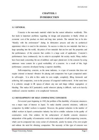
  • 3. Introduction Thapar University, Patiala Page 3 Fig. 1.1: Necessity of Self- Compacting Concrete (Ouchi and Hibino, 2000) The method for achieving self-compactability involves not only high deformability of paste or mortar, but also resistance to segregation between coarse aggregate and mortar when the concrete flows through the confined zone reinforcing bars. The frequency of collision and contact between aggregate particles can increase as the relative distance between the particles decreases and then internal stress can increase when concrete is deformed, particularly near obstacles. Research has found that the energy required for flowing is consumed by the increased internal stress, resulting in blockage of aggregate particles. Limiting the coarse aggregate content, whose energy consumption is particularly intense, to a level lower than normal is effective in avoiding this kind of blockage. Highly viscous paste is also required to avoid the blockage of coarse aggregate when the concrete flows through obstacles. When the concrete is deformed, paste with a high viscosity also prevents localized increases in internal stress due the approach of coarse aggregate particles. High deformability can be achieved only by the employment of a super-plasticizer, keeping the water-powder ratio to a very low value. Additionally, the paste or mortar has to deform well too. Contact and collision between aggregates as well as the interparticle friction increase with the decreases in relative distance between aggregates particles in the concrete mix, resulting in the blockage of aggregate particles. Limiting coarse aggregate volume increases inter-particle separation and reduces the inter-particle friction and collisions resulting in minimization of the blockage leading to improvement in passing ability. Skill of Workersl Self – Compacting Concrete Durable Concrete Structure Decreas In the
  • 4. Introduction Thapar University, Patiala Page 4 Fig. 1.2: The schematic composition of SCC (Brouwers and Radix, 2005) The increase of paste volume with emphasis to low water powder ratio (w/p) in presence of compatible chemical admixtures further strengthens the fluidity and helps in attaining homogeneity. Adequate homogeneity improves viscosity of the mix, which in turn enhances the segregation resistance. An optimum balance between fluidity and viscosity is the key to achieve efficient self-compacting characteristics of the concrete mix at fresh state. In SCC, the powder contains binder component consisting of ordinary Portland cement (OPC), mineral admixtures like fly ash along with/ without filler material like limestone powder, dolomite etc. To achieve moderate plastic viscosity and low yield value, multiple chemical admixtures are required. Special chemical admixture like viscosity modifier admixture (VMA) is used for controlling the viscosity of the mix and super plasticizer for lowering the yield stress. In addition, the characteristics of fine and coarse aggregates play very important role on the yield stress of the mix. Fig. 1.3: Mechanism for achieving self-compactability. (Okamura and Ouchi, 2003)
  • 5. Introduction Thapar University, Patiala Page 5 Fig. 1.4: Methods to achieve self-compactability of fresh concrete (Okamura and Ouchi, 2003) 1.4 PROPERTIES AND TESTS OF SELF-COMPACTING CONCRETE Fresh SCC must possess at required levels the following key properties related to workability: Filling ability: This is the ability of the SCC to flow, spread and fill into all spaces within the formwork under its own weight. Passing ability: This is the ability of the SCC to flow through tight openings such as spaces between steel reinforcing bars, under its own weight without blocking them. Resistance to segregation: The SCC must meet the required levels of properties and its composition remains uniform throughout the process of transport and placing that is keeps the sand and aggregate in suspension.
  • 6. Introduction Thapar University, Patiala Page 6 Fig.1.5: Basic workability requirements for successful casting of SCC (Khayat, 1999) 1.4.1 PROPERTIES Some of the important tests conducted on fresh SCC to evaluate its workability are briefly explained and summarized below in a table: Table 1.1: Test methods to evaluate the workability properties of SCC (EFNARC, 2002). Property Test Methods Laboratory (Mix Design) Field (Quality Control) Filling Ability Slump Flow Test T50 Flow Test V-Funnel Test Orimet Test Slump Flow Test T50 Flow Test V-Funnel Test Orimet Test Passing Ability L-Box Test U-Box Test Fill Box Test J-Ring Test Segregation Resistance GTM Test V-Funnel At T5min GTM Test V-Funnel At T5mins U-type test: Of the many testing methods used for evaluating self-compact ability, the U-type
  • 7. Introduction Thapar University, Patiala Page 7 test (Fig. 1.6) proposed by the Taisei group is the most appropriate, due to the small amount of concrete used, compared to others (Ferraris, 1999). This test is used to measure the filling ability of SCC. The apparatus consists of a vessel that is divided by a middle wall into two compartments. It provides a good direct assessment of passing ability. For conducting the U-box test, one of the compartments of the apparatus is filled with the concrete sample and filled concrete is left to stand for 1 minute. Then the sliding gate is lifted to allow the concrete to flow out into the other compartment. After the concrete comes to rest, the height of the concrete in the compartment that has been filled is measured in two places and the mean height (H1) is calculated. Also the height in the other compartment (H2) is measured. The filling height is then calculated as H1- H2. The whole test has to be performed within 5 minutes. If the concrete flows as freely as water, at rest it will be horizontal, so H1- H2 = 0. Therefore, the nearer this test value, that is, the filling height', is zero, the better the flow and passing ability of SCC (EFNARC, 2002). Fig. 1.6: U-type test (EFNARC, 2002) Slump Flow test: The slump flow test is used to assess the horizontal free flow of SCC in the absence of obstructions. The basic equipment used is the same as for the conventional Slump test. The test method differs from the conventional one by the fact that the concrete sample placed into the mold is not rodded and when the slump cone is removed the sample collapses
  • 8. Introduction Thapar University, Patiala Page 8 (Ferraris, 1999). The diameter of the spread of the sample is measured, that is a horizontal distance is determined as opposed to the vertical distance in the conventional Slump test. The Slump Flow test can give an indication as to the consistency, filling ability and workability of SCC. The SCC is assumed of having a good filling ability and consistency if the diameter of the spread reaches values between 650mm to 800mm (EFNARC, 2002). Fig. 1.7: Slump flow test (Zhimin et al., 2008) Orimet test: The test is based on the principle of an orifice rheometer applied to fresh concrete (Bartos, 2000). The test involves recording of time that it takes for a concrete sample to flow out from a vertical casting pipe through an interchangeable orifice attached at its lower end. The shorter the Flow-Time, the higher is the filling ability of the fresh mix. The Orimet test also shows potential as a means of assessment of resistance to segregation on a site. L-Box test: This method uses a test apparatus comprising of a vertical section and a horizontal trough into which the concrete is allowed to flow on the release of a trap door from the vertical section passing through reinforcing bars placed at the intersection of the two areas of the apparatus (Dietz et al., 2000). The time that it takes the concrete to flow a distance of 200mm and 400mm into the horizontal section is measured, as is the height of the concrete at both ends of the apparatus (H1 & H2). The L-Box test can give an indication as to the filling ability and passing ability.
  • 9. Introduction Thapar University, Patiala Page 9 Fig. 1.8: Schematic of L-box (Grdic et al., 2010). Orimet/J-Ring combination test: This recently developed test involves the J-Ring being placed centrally below the orifice of the Orimet apparatus, allowing the discharged mix to fall into it and flow outwards (Bartos, 2000). The Orimet time is recorded as in the conventional Orimet test, along with the diameter of the concrete spread and the height of the concrete within the J-Ring. The more dynamic flow of concrete in this test simulates better the behaviour of a SCCmix when placed in practice compared with the Slump-Flow variation. The Orimet/J-Ring combination test will be used in the future as a method of assessing filling ability, passing ability and resistance to segregation (Bartos, 2000). Fig: 1.9 Orimet test (EFNARC, 2002)
  • 10. Introduction Thapar University, Patiala Page 10 V-funnel test: Viscosity of the self-compacting concrete is obtained by using a V-funnel apparatus, which has certain dimensions (Fig. 1.10), in order for a given amount of concrete to pass through an orifice (Dietz et al., 2000). The amount of concrete needed is 12 litres and the maximum aggregate diameter is 20 mm. The time for the amount of concrete to flow through the orifice is being measured. If the concrete starts moving through the orifice, it means that the stress is higher than the yield stress; therefore, this test measures a value that is related to the viscosity. If the concrete does not move, it shows that the yield stress is greater than the weight of the volume used. Fig 1.10: V-funnel (Dietz et al., 2000) GTM Segregation test: This is a very recent test measuring the separation of aggregate in a sample after a period of time and wet sieving. The test has a potential for detection of tendency to segregate (Dehn et al., 2000). It completes the tests (Slump-Flow, L-Box, etc.) carried out to estimate the filling ability in free or shut-in environment (that is with some "wall-effect") by specifying the segregation resistance. This test can be used in laboratory when developing a concrete mix, as well as on site, when carrying out suitability tests on the delivered concrete. Slump Flow/J-Ring combination test: This test (Fig. 1.11) involves the slump cone being placed inside a 300mm diameter steel ring attached to vertical reinforcing bars at appropriate spacing (the J-Ring itself) (Kosmatka et al., 2002). The number of bars has to be adjusted depending on the maximum size aggregate in the SCC mix. Like in the Slump Flow test, the diameter of the spread and the T-50 time are recorded for the evaluation of SCC viscosity. The Slump Flow/J-Ring combination test is an improvement upon the Slump Flow test on its own
  • 11. Introduction Thapar University, Patiala Page 11 as it aims to assess also the passing ability of the fresh mix. In this respect, the SCC has to pass through the reinforcing bars without separation of paste and coarse aggregate. Fig. 1.11 : Slump Flow/J-Ring combination test (Kosmatka et al., 2002) Typical acceptance criteria for SCC with a maximum aggregate size of up to 20 mm are presented in Table 1.2. Table 1.2 : Acceptance criteria for Self-compacting Concrete (EFNARC, 2002) Method Unit Minimum Value Maximum Value Slump flow Mm 650 800 J –Ring Mm 0 10 V- Funnel Sec 6 12 L-Box (H2/H1) 0,8 1,0 U- Box (H2-H1)mm 0 30 Orimet Sec O 5 Fill Box % 90 100 1.5 ADVANTAGES AND DISADVANTAGES OF SELF-COMPACTING CONCRETE 1.5.1 ADVANTAGES  No vibration of fresh concrete is necessary during placement into forms.  Placement of concrete is easier.
  • 12. Introduction Thapar University, Patiala Page 12  Faster and more efficient placement of fresh concrete is achieved. Total concreting time is reduced.  Energy consumption is reduced.  Required number of workers on construction site is reduced.  Safer and healthier working environment is obtained.  High quality of placed concrete is achieved, regardless the skill of the workers.  Good bond between concrete and reinforcement is obtained, even in congested reinforcement.  High quality of concrete surface finish is obtained with no need for subsequent repair.  Improved form surface finish and reduced need to repair defects such as bug holes and honeycombing.  Improved ability of concrete to flow into intricate spaces and between congested reinforcement.  Reduced construction costs due to reduced labour costs and reduced equipment purchase and maintenance costs.  Increased construction speed due to fewer construction tasks.  Faster unloading of ready mixed concrete trucks.  Improved working conditions with fewer accidents due to elimination of vibrators.  Improved durability and strength of the hardened concrete in some cases.  Reduced noise generated by vibrators. 1.5.2 DISADVANTAGES  Increased material costs, especially for admixtures and cementitious materials.  Increased formwork costs due to possibly higher formwork pressures and to prevent leakage.  Increased technical expertise required to develop and control mixtures.  Increased variability in properties, especially workability.  Increased quality control requirements.  Reduced quality of hardened properties in some cases possibly including modulus of  Elasticity and dimensional stability—due to factors such as high paste volumes or finer combined aggregate grading.  Delayed setting time in some cases due to the use of admixtures.  Requires more trial batches at laboratory as well as at plants.
  • 13. Introduction Thapar University, Patiala Page 13  Increased risk and uncertainty associated with the use of a new product. 1.6 APPLICATIONS OF SELF-COMPACTING CONCRETE SCC technology originated in Japan in the early 1980s, arising out of durability concerns due to poor compaction on the job site. Use of SCC quickly became widespread in Japan, especially since the government implemented a plan to use SCC for 50% of all concrete jobs by 2003( FrancesYang,2004 ). It then spread to Europe in the 1990’s after invention of polycarboxylate super plasticizers. In the UK, The Concrete Society has issued official measures to expand the use of SCC as a means of replacing vibratory compaction. In the US and Canada, SCC technology is available mostly in the form of proprietary concrete mixes from ready-mix producer subsidiaries of cement manufacturers such as Lafarge and Lehigh. It is also available as specialized admixtures combining super plasticizer and viscosity modifiers. Given how important maintaining mix quality of SCC is for its successful performance, using SCC demands increased attention and skill. In particular, superplasticizer dramatically increases the sensitivity of the mix to water. This allows little room for error in mix proportioning, which can become problematic in-field when weather and timing cannot always be controlled by the contractor. In light of this, most applications of SCC in the US have been limited to precast construction due to tighter quality control ensured in-plant compared to in- field. However, the industry has shown eagerness to expand its use. Whereas in 2000, only about 10% of the precast industry had tried SCC, by 2003, the number jumped to almost 90%, of which 40% used it on a regular basis. Some notable projects have utilized SCC in Canada. One is the Toronto International Airport, where concrete had to be pumped upwards from the ground to form 101-foot tall columns. Another project in Vancouver, B.C used SCC so little patching would be required for highly visible, outrigger columns. In Asia, SCC was used for a monolithic foundation mat in Singapore where the concrete needed to reach massive dimensions in a short amount of time. In the US, a high-strength SCC was imperative for constructing tightly reinforced elements poured in below-freezing weather for the 68-story Trump Tower in New York City.SCC has also shown successful application for residential projects, such as homes for Habitat for Humanity in the Houston area. Some of the structures built with self compacting concrete are Burj Dubai , Arlanda airport control tower Stockholm, Sweden, National Museum of 21st Century in Rome , Italy.
  • 14. Introduction Thapar University, Patiala Page 14 ( Ouchi et al., 2003 ) A typical application example of Self-compacting concrete is the two anchorages of Akashi-Kaikyo (Straits) Bridge opened in April 1998, a suspension bridge with the longest span in the world (1,991 meters) . The volume of the cast concrete in the two ahchorages amounted to 290,000 m3. A new construction system, which makes full use of the performance of self -compacting concrete, was introduced for this. The concrete was mixed at the batcher plant beside the site, and was the pumped out of the plant. It was transported 200 meters through pipes to the casting site, where the pipes were arranged in rows 3 to 5 meters apart. The concrete was cast from gate valves located at 5 meter intervals along the pipes. These valves were automatically controlled so that a surface level of the cast concrete could be maintained. In the final analysis, the use of self compacting concrete shortened the anchorage construction period by 20%, from 2.5 to 2 years. Self-compacting concrete was used for the wall of a large LNG tank belonging to the Osaka Gas Company, whose concrete casting was completed in June 1998 . The volume of the self-compacting concrete used in the tank amounted to 12,000 m3. The Ritto Bridge is a PC extra-dosed bridge with corrugated steel webs on the New Meishin Expressway in Japan . The highest pier is 65-meter high. High strength concrete and reinforcements, of which specified compressive strength and yield strength are 50 MPa and 685 MPa respectively, were applied to the construction of the pier to meet the earthquake resistance. Arrangement of reinforcement was very dense; therefore SCC was chosen to obtain good workability for the pier construction. The Sodra Lanken Project (SL) is the largest infrastructure project in Sweden. The overall cost of the SL is estimated to around 800 million USD. The SL will provide a six kilometre four lane west - east link in the southern parts of Stockholm. The SL project includes seven major junctions, with bridges, earth retention walls, tunnel entrances and concrete box tunnels. The overall length of the rock tunnels are16.6 kilometres. They are partly lined with concrete. The concrete volume used in the project amounts 225,000 cubic meters. The duration of the SL project is estimated to last 6 years (1998 - 2004). The experiences with SCC are generally good. SCC has primarily been used in connection with constructions difficult to compact by normal vibration and high demands on aesthetics, for examples, in concrete rock lining, underground installation structures and rock tunnel entrances, retention walls with negative inclination and relief structures. In India Delhi Metro Project have used SCCin large scale for dome construction, tunnel lining , column casting. Hindustan Construction Company have also carried out considerable studies on the use of High Volume Fly Ash self compacting concrete for domes walls in turbine
  • 15. Introduction Thapar University, Patiala Page 15 building in Rajasthan Power Project ,and Concrete for piers in Bandra Worli Sea Link Projects.At Tarapur Atomic Power Project SCC was used for the construction of three walls of a pump house .The height of the wall was 14.4 m and it was done in 5 pours.At Kaiga Nuclear Power Project (Karnataka) SCC of characteristic strength 30 MPa was used in the two Mock up structures one being heavily reinforced column with two beams passing through it and the other being a thin wall (140mm thick). 1.7 LIMITATIONS OF SELF-COMPACTING CONCRETE 1.7.1 SCC PRODUCTION  Production of SCC requires more experience and care than the conventional vibrated concrete. The plant personnel would need training and experience to successfully produce and handle SCC. In the beginning, it may be necessary to carry out more tests than usual to learn how to handle SCC and gain the experience.  Before any SCC is produced at the plant and used at the job site, the mix must be properly designed and tested to assure compliance with the project specifications. The ingredients and the equipment used in developing the mix and testing should be the same ingredients and equipment to be used in the final mix for the project.  Most common concrete mixers can be used for producing SCC. However, the mixing time may be longer than that for the conventional vibrated concrete. SCC is more sensitive to the total water content in the mix. It is necessary to take into account the moisture/water content in the aggregates and the admixtures before adding the remaining water in the mix. The mixer must be clean and moist, and contains no free water.  Admixtures for the SCC may be added at the plant or at the site. There is cost benefit in adding the admixtures at the site. Conventional ready-mix concrete can be bought at a lower cost than the cost of SCC bought from a ready-mix supplier. 1.7.2 TRANSPORTATION  The truck drivers should be given oral and written instructions for handling SCC. The truck drivers must check the concrete drum before filling with SCC to make sure that the drum is clean and moist, but with no free water. Extra care must be taken for long
  • 16. Introduction Thapar University, Patiala Page 16 deliveries. In addition to the usual information, the delivery note should show the following information:  Slump flow - target value and acceptable range.  Production time - time when it was produced.  Instruction for adding admixtures at the site, if allowed.  The truck drivers should not be allowed to add water and/or admixtures during transit. 1.7.3 FORM SYSTEM  All commonly used form materials are suitable for SCC. For surface quality of SCC, wood is better than plywood, and plywood is better than steel. More pores seem to form on the surface when the form skin is colder than the SCC. During cold weather placement of SCC, it may be necessary to insulate the formwork to maintain temperature and normal setting time. SCC is more sensitive to temperature during the hardening process than the conventional vibrated concrete.  Due to the cohesiveness of SCC, the formwork does not need to be tighter than that for conventional vibrated concrete.  Higher form pressures than normal were not observed even at high rate of concrete placement. However, it is recommended that the formwork be designed for hydrostatic pressure, unless testing has shown otherwise. 1.7.4 CASTING ON SITE  A pre-SCCplacement meeting with all personnel involved in the SCCplacement would be beneficial. The SCC placement plan, including QC/QA, and the roles and responsibilities of the field personnel should be explained and understood.  In addition to the normal testing, the slump flow, T50 and L-box tests are useful to check SCC at the job site before placement.  SCC can flow horizontally a distance of 15 to 20m without segregation. A well- designed SCC may have a free fall of as much as 8m without segregation. However, it is recommended that the distance of horizontal flow be limited to 10m and the vertical free fall distance be limited to 5m.  For deck slab of a bridge, it would be difficult for the SCC to flow too far. This could be handled by designing an SCC with a lower slump flow. With a lower slump flow, a bridge deck with a slope of 2% could also be accomplished.
  • 17. Introduction Thapar University, Patiala Page 17  If an SCC placement is interrupted and the concrete has started to harden, it would be necessary to .wake up. the placed concrete by striking a stick or board into the concrete several times before starting the placement again.  SCC takes some time before the hardening starts, especially during cold weather conditions. When it starts to harden, the process is very rapid, which can cause problems in levelling and treating large surface areas. 1.7.5 SURFACE FINISHING AND CURING  Finishing and curing of SCC can follow the good practices of super plasticized high performance concrete. Surface of SCC should be roughly levelled to the specified dimensions, and the final finishing applied as necessary before the concrete hardens.  SCC tends to dry faster than conventional vibrated concrete, because there is little or no bleeding water at the surface. SCC should be cured as soon as practicable after placement to prevent surface shrinkage cracking. 1.7.6 COLD JOINT  When placing a new layer of SCC on old SCC, the bond between the old and new SCC is equal to or better than in the case of conventional vibrated concrete. Normal vibration will not destroy the concrete, such as in the case of placing conventional vibrated concrete on fresh SCC. This may be necessary when the surface slope is greater than practicable for SCC (Ouchi et al., 2003). 1.8 WORLD-WIDE CURRENT SITUATION OF SELF-COMPACTING CONCRETE Self-compacting concrete has already been used in several countries. In Japan, major construction projects included the use of SCC in the late ’90s. Today, in Japan, efforts are being made to free SCC of the “special concrete” label and integrate it into day-to-day concrete industry production. Currently, the percentage of self-compacting concrete in annual product of ready-mixed concrete (RMC), as well as precast concrete (PC), in Japan is around 1.2% and 0.5% of concrete products. In the United States, the precast industry is also leading SCC technology implementation through the Precast/Pre-stressed Concrete Institute (PCI) which has done some research on the use of SCC in precast/pre-stressed concretes starting with 1999. It is estimated that the daily production of SCC in the precast/pre-stressed industry in the United
  • 18. Introduction Thapar University, Patiala Page 18 States will be 8000 m3 in the first quarter of 2003 (around 1% of the annual ready-mix concrete). Furthermore, several state departments of transportation in the United States (23 according to a recent survey). Bartos, (2000) are already involved in the study of SCC. With such a high level of interest from the construction industry, as well as manufacturers of this new concrete, the use of SCC should grow at a tremendous rate in the next few years in the United States. However, even if it is made from the same constituents the industry has used for years, the whole process, from mix design to placing practices, including quality control procedures, needs to be reviewed and adapted in order for this new technology to be applied properly. Research regarding the self-compacting concrete was also carried out in Canada, few years after the concept was introduced in Japan. Institute for Research in Construction, Canadian Precast/Pre- stressed Concrete Institute, CONMET-ICON, and ISIS are some of the bodies which studied various aspects of the new technology. The introduction of the SCC in Europe is largely connected with the activities of the international association RILEM, France, particularly of its Technical Committee TC145-WSM on “Workability of Fresh Special Concrete Mixes” (Dhir and Dyer, 1999). The TC145-WSM was founded in 1992 and immediately attracted expert memberships from all over the world. The aim was to look at the production stage of a number of “special” concretes and identify workability parameters and other characteristics of the mixes in their fresh state that governed the reliable and economical achievement of the “special” or “high-performance” parameters the concretes offered. As the importance of the SCC became widely recognized, other European countries, Germany, Sweden, UK, Denmark, Netherlands, Norway, Finland, etc., have decided to keep up with the developments in this area. For example, in Sweden, the SCC market share was at five percent in RMC and PC in 2002, and was expected to double in 2003. Housing and tunnelling, as well as bridge construction for the Swedish National Road Administration were the main areas of use for SCC. In the Netherlands and Germany, the precast industry is mainly driving the development of SCC, with an expected eight percent of market share in 2003 in Netherlands. Today, self- compacting concrete is being studied worldwide, with as per presented at almost every concrete-related conference, but until now - year 2003 - there is no universally adopted standardized test method for evaluation of self-compatibility of this concrete. In India ,during the last few years ,attempts were made in the laboratories and in the field to develop and use SCC. Some pioneering efforts have been made in Delhi Metro projects in association with L&T and MBT .Nuclear Power Corporation , Gammon India, Hindustan Construction Company have made large scale laboratory trials .Laboratory studies conducted
  • 19. Introduction Thapar University, Patiala Page 19 at SERC(Structural engineering research centre) Chennai, Indian Institute of Technology at Madras, Roorkee and other places have given enough inputs and confidence to adopt SCC in India. Of all the places Delhi Metro project have used SCC in large scale for dome construction, tunnel lining, column casting.( Sood et al. 2009 )In India, the development of concrete possessing self compacting properties is still very much in its infancy.During the last couple of years, few attempts were made using European Guidelines for testing SCC in the laboratories and in the field. SCC was used by Nuclear Power Corporation of India Ltd. at Tarapur, Kaiga and Rajasthan Atomic Power Project (RAPP). Some pioneering efforts have been made in Delhi Metro Project. In all the above investigations European standards were followed for determining rheological properties of Self compacting concrete. Today, self-compacting concrete is being studied worldwide, with papers presented at almost every concrete-related conference, but until now there is no universally adopted standardized test method for evaluation of self-compact ability of this concrete. Currently, the use of self-compacting concrete is being rapidly adopted in many countries. The use of self- compacting concrete should overcome concrete placement problems associated with the concrete construction industry. However, there still is a need for conducting more research and development work for the measurement and standardization of the methods for the evaluation of the self-compacting characteristics of SCC. 1.9 NEED FOR THIS RESEARCH There are many situations in today’s construction market that make SCCan interesting alternative to conventional slump concrete. In general, cost savings and/or performance enhancement tend to be the driving forces behind the added value of SCC. Contractors, producers and owners are under great pressure to produce better quality construction at lower costs of labour, materials and equipment. They are also faced with tougher environmental and safety regulations, and increased insurance costs. The economic benefits of a less intensive construction environment results in labour savings, time savings from higher productivity, and greater flexibility of design. SCC offers some help in all of the following areas. The main barrier to the increased use of SCC seems to be the lack of experience of the process, and the lack of published guidance, codes and specifications. This situation will improve, however, as experience and knowledge increases and each country begins to produce its own guidance and specifications for the production of SCC with local marginal aggregates and the harsh
  • 20. Introduction Thapar University, Patiala Page 20 environmental conditions prevailing in the region. Therefore, there is a need to conduct studies on SCC. 1.10 FOUNDRY SAND A foundry produces metal castings by pouring molten metal into a preformed mould to yield the resulting hardened cast. The metal casts include iron and steel from the ferrous family and aluminium, copper, brass and bronze from non-ferrous family (Siddique, 2008). Foundry sand is high quality silica sand used as a moulding material by ferrous and non-ferrous metal casting industries. It can be reused several times in foundries but, after a certain period, cannot be used further and becomes waste material, referred to as used or spent foundry sand (UFS or SFS). The majority of spent moulding sands are classified as nonhazardous waste (that is not corrosive, ignitable, reactive or toxic) (Siddique and Noumowe, 2008).Foundries use high quality size-specific silica sands for use in their moulding and casting operations. The raw sand is normally of a higher quality than the typical bank run or natural sands used in fill construction sites. In the casting process, moulding sands are recycled and reused multiple times. Eventually, however, the recycled sand degrades to the point that it can no longer be reused in the casting process. When it is not possible to further reuse sand in the foundry, it is removed from the foundry and is termed as spent foundry sand. The physical and chemical characteristics of foundry sand will depend in great part on the type of casting process and the industry sector from which it originates. In a recent study, (Siddique et al. 2009) reported that in the United States alone, up to 10 million tons of foundry sand are discarded annually and are available for recycling. Foundries purchase new, virgin sand to make casting moulds and the sand is reused numerous times within the foundry. However, heat and mechanical abrasion eventually render the sand unsuitable for use in casting moulds, and a portion of the sand is continuously removed and replaced with virgin sand. The spent foundry sand, that is, the sand that is removed, is either recycled in a non-foundry application or land filled. 1.11 PRODUCTION OF FOUNDRY INDUSTRY IN INDIA AND WORLD There are about 35,000 foundries in the world with annual production of 90 million tonnes. In terms of number of foundries China has the highest score (9374), followed by India (6000). The share of Iron foundries is the maximum that is almost 56%, followed by steel with 14% and then the non-ferrous ones with 30%. The growing environmental concerns and
  • 21. Introduction Thapar University, Patiala Page 21 globalization of economies have led to a closure of some 8000 foundries in Europe. These countries have been contemplating to shift their business to the low labour cost centres that is, the developing countries. The impetus for foundry sector in India was given by the Jute industry in Bengal and the cotton industry in Mumbai in late 19th century. The establishment of TISCO, Bengal Iron Company and the IISCO led to some remarkable new uses of castings, in domestic as well as industrial areas. India ranks second in the world based on the number of foundry units present (4550 units) - after China – and fourth in terms of total production (7.8 million tonnes) (42nd Census of World Casting Production – 2007). Apart from the registered 4550 units there are several unregistered units, which according to various sources range approximately from 1500 to 5000 units. As per the IREDA- CII Report 2004, there are around 10,000 foundry units present in India including registered and unregistered units. Considering that 4550 units are registered, the total number of units unregistered is around 5450 units. As per estimation of experts of the foundry sector, there are around 1500 unregistered foundry units that are scattered across the country. This discrepancy in unregistered units is mainly due to the fact that the 5450 units included all kinds of micro and small units engaged in castings. Whereas the 1500 units data incorporates only those foundry units that are engaged in grey iron casting and use conventional cupola and excludes those units that are too micro in nature and use crucible for melting of metals. Also several foundry units had closed due to non compliance with the pollution standard set by the government for example Howrah, Agra and nearby areas. The foundry produces a wide variety of castings such as manhole covers, pipe and pipe fittings, sanitary items, tube well body, metric weights, automobile components, railway parts, electric motor, fan body etc. 90% of the castings produced are from the SSI sector. Most of these units are situated in clusters, with cluster size ranging from 30- 500 units. (Bhimani et al. 2013) 1.12 TYPES OF FOUNDRY SAND Classification of foundry sands depends upon the type of binder systems used in metal casting. Generally two types of binder systems are used and based on that foundry sands are classified as: clay-bonded systems (green sand) and chemically bonded systems. Both types of sands are suitable for beneficial use but they have different physical and environmental characteristics.(Siddique and Singh , 2011) 1.12.1 GREEN SAND
  • 22. Introduction Thapar University, Patiala Page 22 Clay-bonded (Green) sand is composed of naturally occurring materials which are blended together; high quality silica sand (85–95%), bentonite clay (4–10%) as a binder, a carbonaceous additive (2–10%) to improve the casting surface finish and water (2–5%). It is black in colour due to carbon content. Green sand is the most commonly used moulding media by foundries. The silica sand is the bulk medium that resists high temperatures while the coating of clay binds the sand together. The water adds plasticity. The carbonaceous additives prevent the “burn-on” or fusing of sand onto the casting surface. Green sands also contain trace chemicals such as MgO, K2O, and TiO2. The green sand used in the process constitutes upwards of 90% of the moulding materials used. 1.12.2 CHEMICALLY BONDED SANDS Chemically bonded sands are used both in core making where high strengths are necessary to withstand the heat of molten metal, and in mould making. Chemically bonded sand consists of 93–99% silica and 1–3% chemical binder. Silica sand is thoroughly mixed with the chemicals; a catalyst initiates the reaction that cures and hardens the mass. There are various types of chemical binder systems used in the foundry industry. The most common chemical binder systems used are phenolic-urethanes, epoxy-resins, furfyl alcohol, and sodium silicates. Chemically bonded sands are generally light in colour and in texture than clay bonded sands. Waste foundry sand (WFS) is also referred as spent foundry sand (SFS) or used foundry sand (UFS). 1.13 PROPERTIES OF WASTE FOUNDRY SAND 1.13.1 PHYSICAL PROPERTIES Generally, waste foundry sand (WFS) is sub-angular to round in shape. Green sands are black or grey, whereas chemically bonded sands are of medium tan or off-white color. Grain size distribution of waste foundry sand is uniform with 85-95% of the material in between 0.6 mm to 0.15 mm and approximately 5 to 20% of foundry sand can be smaller than 0.075 mm. Dayton et al. (2010) mentioned that sand (0.05 to 2 mm) was the dominant size fraction in the 39 spent foundry sands ranging from 76.6% to 100% with a median of 90.3%.The specific gravity of foundry sand varies between 2.39 and 2.79. Waste foundry sand has low absorption capacity and is non-plastic. Physical properties of waste foundry as reported by Javed and Lovell (1994), Naik et al. (2001), Guney et al. (2010) and Siddique et al. (2011), are given in Table 1.3
  • 23. Introduction Thapar University, Patiala Page 23 Table 1.3: Typical Physical Properties of Waste Foundry Sand (Siddique and Singh , 2011) Property Javed and Lovell Naik et al. Guney et al. Siddique et al. (1994) (2001) (2010) (2011) Specific gravity 2.39-2.55 2.79 2.45 2.61 Fineness modulus - 2.32 - 1.78 Unit Weight (kg/m3) - 1784 - 1638 Absorption (%) 0.45 5 - 1.3 Moisture content (%) 0.1-10.1 - 3.25 - Clay lumps and 1-44 0.4 - 0.9 friable particles Materials finer than - 1.08 24 18 75µm (%) 1.13.2 CHEMICAL PROPERTIES Chemical composition of the waste foundry sand depends on the type of metal, type of binder and combustible used. The chemical composition of the foundry sand may influence its performance. Waste foundry sand is rich in silica content. It is coated with a thin film of burnt carbon, residual binder (bentonite, sea coal, resins/chemicals) and dust. Silica sand is hydrophilic and consequently attracts water to its surface. Chemical composition of WFS as reported by American Foundryman’s Society ( 1991), Guney et al. (2010), Etxeberria et al. (2010) and Siddique et al. (2011) is given in Table 1.4 It has been reported that some waste foundry sands can be corrosive to metals (MNR, 1992). Due to the presence of phenols in foundry sand, it raises concerns that precipitation percolating through stockpiles could mobilize leachable fractions, resulting in phenol discharges into surface or ground water supplies. Table 1.4: Chemical Composition of Foundry Sand (Siddique and Singh, 2011)
  • 24. Introduction Thapar University, Patiala Page 24 Constituent Value (%) American Guney et al. Etxeberria et al. Siddique et al. Foundryman's (2010) (2010) (2011) Society ( 1991) SiO2 87.91 98 95.1 78.81 Al2O3 4.7 0.8 1.47 6.32 Fe2O3 0.94 0.25 0.49 4.83 CaO 0.14 0.035 0.19 1.88 MgO 0.3 0.023 0.19 1.95 SO3 0.09 0.01 0.03 0.05 Na2O 0.19 0.04 0.26 0.1 K2O 0.25 0.04 0.68 - TiO2 0.15 - 0.04 - Mn2O3 0.02 - - SrO 0.03 - - LOI 5.15 - 1.32 2.15 1.13.3 MECHANICAL PROPERTIES Waste foundry sand has good durability properties as measured by low Micro-Deval abrasion (Ontario Ministry of Transportation, Canada 1996). Javed and Lovell (1994) have revealed relatively high soundness loss, which may be due to the samples of bound sand loss and not a breakdown of individual sand particles. The angle of shearing resistance (also known as friction angle) of waste foundry sand varies between 33 and 40 degrees, which is comparable to that of conventional sands. Typical mechanical properties of waste foundry sand are given in Table 1.5 Table 1.5: Typical Mechanical Properties of Spent Foundry Sand (Siddique and Singh ,2011)
  • 25. Introduction Thapar University, Patiala Page 25 Property Results Micro-deval abrasion loss (%) < 2 (MNR–1992) Magnesium sulfate soundness loss 5 – 15 (%)(MNR–1992) 6 – 47 Friction angle (deg) 33 – 40 California bearing ratio (%) (Javed 4 – 20 and Lovell 1994) 1.14 APPLICATIONS OF WASTE FOUNDRYSAND Indian foundries produce approximately 1.71 million tons of waste foundry sand each year (Metal World, 2006). In United States of America, metal casting foundries dispose of approximately 9 million metric tons of waste foundry sand (WFS) in landfills in 2000 (Winkler and Bol’shakov, 2000). United States’s average land-filling tipping fee of foundry by products is US $15-75 per ton inclusive of storage, transportation and labour costs (Winkler et al. 1999). The annual cost of WFS disposal was around US $ 135- 675 million. The considerable disposal expense has made the current practice of WFS disposal in landfills less favourable. Besides the financial burden to the foundries, land-filling WFS also makes them liable for future environmental costs, remediation problems and regulation restrict ions. This issue is increasingly addressed by alternate options of reusing WFS beneficially. Waste foundry sand is made up of mostly natural sand material. Its properties are similar to the properties of natural or manufactured sand. Thus it can normally be used as a replacement of sand. Beneficial reuses of WFS span a variety of applications related to infrastructure engineering rehabilitation works. Some of the researchers have reported the possible use of waste foundry sand in different civil engineering applications, which are given in Table1.6. These alternate applications offer cost savings for both foundries and user industries and an environmental benefits at the local and national level.
  • 26. Introduction Thapar University, Patiala Page 26 Table 1.6: Uses of WFS in Various Applications Author’s Name Application Javed and Lovell(1994), Traeger(1987), Kleven et al.(2000), MOEE(1993), Abichou et al.(1998), Mast and Highway Fox(1998), Kirk(1998) and Gunney et al.(2006) Nail et al. (2003; 2004), Tikalsky et al. (1998) and Siddique et Controlled low strength al.(2008) materials Dungan et al. (2006), Deng and Tikalsky (2008) Geotechnical Field Braham A. (2002) Hot Mix Asphalt Ham RK and Boyle (1981), Fero et al. (1986), Engroff et al. Leachate Characteristic (1989), Siddique et al. (2010) and Dungan et al. (2009) Seung-Whee and Woo-Keun(2006), Naga and El- Maghraby(2003), Pereiraa et al. (2006) and Quaranta et al. (2004) Ceramic material El Haggar and El Hatow(2009) Manhole cover Periraa et al. (2004) Refractory Mortars Colombo et al. (2003), Ferraris et al. (2001), Interization and Reuse of Waste materials by Geo and Drummond (1999) Vitrification Santurde et al. (2011) Clay Brick Environment Protection Agency (2007) EPA has found that spent foundry sands produced by iron, steel, and aluminium foundries are rarely hazardous. EPA supports the use of spent foundry sands from these foundry types in the following applications:  As partial replacement for fine aggregate in asphalt mixtures.
  • 27. Introduction Thapar University, Patiala Page 27  As partial replacement for fine aggregate in Portland cement concrete.  As source material for the manufacture of Portland cement and  As a sand used in masonry mortar mixes In addition, use of foundry sand from iron, steel and aluminum foundries in flowable fill, road embankments, road base, manufactured soil, agricultural amendments, and similar uses may be appropriate depending on the site and the sand composition. 1.15 ORIENTATION OF THESIS REPORT This thesis is presented in five chapters as detailed below: Chapter-1 Gives the introduction about Self-Compacting Concrete and Foundry Sand Chapter-2 Literature review presents the work done by various researchers in the field of Self-Compacting Concrete. Chapter-3 Details the scheme of experimentation, materials used with their properties, and variables involved, Concrete mixes, mix design, casting of specimens for studying various properties and methodology adopted for testing of different properties. Chapter-4 Gives results and their analysis for the fresh properties, strength properties such as compressive strength, splitting tensile strength and durability properties like sulphate resistance and rapid chloride penetration resistance of the mixes with waste foundry sand and are compared with control concrete. Chapter-5 Gives the major conclusions made in the study. References