Downloaded 17 times
![Maximum measured error
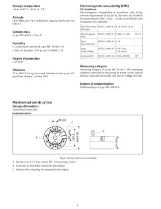
The accuracy data are typical values and correspond to a standard deviation of ±3 σ (normal distribution), i.e. 99.8 % of all the
measured values achieve the given values or better values.
Designation/measuring range Performance characteristics
Digital D/A 1)
Resistance thermometer (RTD)
(3-wire, 4-wire)
Pt100
Pt500
Pt1000
Pt200
0.1 °C (0.18 °F)
0.3 °C (0.54 °F)
0.2 °C (0.36 °F)
1.0 °C (1.8 °F)
0.03 %
0.03 %
0.03 %
0.03 %
Resistance thermometer (RTD)
(2-wire)
Pt100
Pt500
Pt1000
Pt200
0.8 °C (1.44 °F)
0.8 °C (1.44 °F)
0.8°C (1.44 °F)
1.5 °C (2.7 °F)
0.03 %
0.03 %
0.03 %
0.03 %
Thermocouples (TC) Type: K, J, T, E
Type: N, C, D
Type: S, B, R
0.25 °C (0.45 °F)
0.5 °C (0.9 °F)
1.0 °C (1.8 °F)
0.03 %
0.03 %
0.03 %
Resistance transmitters (Ω) 10 to 400 Ω
10 to 2 000 Ω
±0.04 Ω
±0.8 Ω
0.03 %
0.03 %
Voltage transmitter (mV) –20 to 100 mV ±10 μV 0.03 %
1) % refers to the set span. Accuracy = digital + D/A accuracy
Physical input measuring range of sensors
10 to 400 Ω Pt100
10 to 2000 Ω Pt200, Pt500, Pt1000
–20 to 100 mV Thermocouples type: B, C, D, E, J, K, N, R, S, T
Sensor adjustment
Sensor transmitter matching
RTD sensors are one of the most linear temperature measur-
ing elements. Nevertheless, the output must be linearized. To
significantly improve temperature measurement accuracy,
the device allows the use of two methods:
• Callendar-Van-Dusen coefficients (Pt100 resistance ther-
mometer)
The Callendar-Van-Dusen equation is described as:
RT
= R0
[1 + AT + BT2
+ C (T - 100) T3
]
The coefficients A, B and C are used to match the sensor
(platinum) and transmitter in order to improve the accura-
cy of the measuring system. The coefficients for a standard
sensor are specified in IEC 751. If no standard sensor is
available or if greater accuracy is required, the coefficients
for each sensor can be determined specifically with the aid
of sensor calibration.
• Linearization for copper/nickel resistance thermometers
(RTD)
The polynomial equation for copper/nickel is as follows:
RT
= R0
(1 + AT + BT2
)
The coefficients A and B are used for the linearization of
nickel or copper resistance thermometers (RTD).
The exact values of the coefficients derive from the calibra-
tion data and are specific to each sensor.
Sensor transmitter matching using one of the methods ex-
plained above significantly improves the temperature mea-
surement accuracy of the entire system. This is because the
transmitter uses the specific data pertaining to the connected
sensor to calculate the measured temperature, instead of us-
ing the standardized sensor curve data.
1-point adjustment (offset)
Shifts the sensor value
2-point adjustment (sensor trimming)
Correction (slope and offset) of the measured sensor value at
transmitter input
Current trimming (current output fine adjust-
ment)
Correction of the 4 or 20 mA current output value
Non-repeatability
Input
10 to 400 Ω 15 mΩ
10 to 2000 Ω 100 ppm * measured value
–20 to 100 mV 4 μV
Output
≤ 2 μA
Influence of the supply voltage
≤ ±0.0025%/V, with reference to the span
Long-term stability
≤ 0.1 °C/year (≤ 0.18 °F/year) or ≤ 0.05 %/year
Data under reference operating conditions. % refers to the set
span. The larger value is valid.
4](https://image.slidesharecdn.com/azbilindustrialtwochanneltemperaturetransmitter-151111013850-lva1-app6892/85/Advanced-Industrial-Temperature-Transmitter-4-320.jpg)
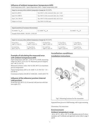
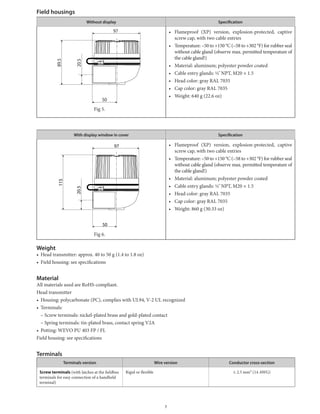
![Dimentions
Output Side
Conduit Entries
M20×1.5
or
1/2 NPT
M4
Internal Ground Screw
57 115
21
21
89.5
94
97
5020.5
M20×1.5
or
1/2 NPT
Sensor Side
Conduit Entries
Without DisplayWith Display[Unit: mm]
Dimensions
for Mounting
Mounting to 2B Pipe
2B Pipe 120
140
120
140
(160.3 *1) (40.5 *1)
*1. Reference value of 2B Pipe
2B Pipe Bracket
(Option) 139.5
45
M4
External Ground Screw
M4
External Ground Screw
8
Mounting to Wall
4 × M6
12 Depth of Screw
Bracket
(Option)
2 × 6.5 Hole
(M6 Screw)
11](https://image.slidesharecdn.com/azbilindustrialtwochanneltemperaturetransmitter-151111013850-lva1-app6892/85/Advanced-Industrial-Temperature-Transmitter-11-320.jpg)


The Advanced Temperature Transmitter ATT082 is a two-channel transmitter that converts sensor signals into a scalable 4-20 mA output signal. It has high accuracy, reliability, and advanced diagnostics. It can connect to RTDs, thermocouples, resistance transmitters, or voltage transmitters. It has various approvals for use in hazardous areas. Its features include sensor backup, drift warning, temperature-dependent switching, corrosion detection, and low voltage detection.


