SlideShare a Scribd company logo
1 of 8
Download to read offline
A STUDY ON THE ACCURACY OF DAYLIGHTING SIMULATION
OF HEAVILY OBSTRCUTED BUILDINGS IN HONG KONG
Edward Ng
Department ofArchitecture, Chinese University of Hong Kong
Shatin, NT, Hong Kong, People Republic of China
ABSTRACT
Hong Kong is the most densely populated city in the
world. The Building Regulations of Hong Kong pre-
scribe a minimum distance between buildings for light-
ing and ventilation. Lately, designers are testing the
prescribed requirements with a performance based ap-
proach using computational simulations. Doubts have
been cast as to their validity and accuracy. This study
compares results obtained by on-site measurements,
calculation and simulated results using Radiance and
Lightscape. The study concludes that both Radiance
and Lightscape over estimate daylight availability by
up to 50% under conditions of high external obstruc-
tion. A work around method is suggested.
INTRODUCTION
Hong Kong is the most densely populated city in the
world. It boasts a development density of 2700 person
per hectare. Typically, residential buildings are built
to a plot ratio of 9 and site coverage of around 50%.
This leads to 40 to 60 storey high buildings built very
closely together. (Figure 1)
ments. For example, it is required that for buildings
100m high, the distance measured from the window
to the opposite wall of another 100m high building
should be no less than 33m. This represents an ob-
struction angle (qL
) of 71.5°.
Recently, developers, architects and engineers fight-
ing to maximize development gains are challenging
the simple geometrical prescription using computa-
tional simulations. The argument is that if the per-
formance of a more densely designed proposal could
achieve or exceed that based on geometrical prescrip-
tion, then the development should be accepted and
approved by the authority. The desire of the profes-
sional to work towards a performance based system is
honourable. However, doubts have been cast as to the
validity and accuracy of the computation simulations
used to support their claims.
This paper examines the issue of accuracy and valid-
ity when using computational simulation to study the
daylighting performance of heavily obstructed residen-
tial buildings in Hong Kong. Two simulation software
commonly available to building professionals, Radi-
ance and Lightscape, were used to compare against
on-site measurement.
A newly developed residential site in Sheung Tak Es-
tate, Tseung Kwan O, one of the many new towns in
Hong Kong, was chosen to be the vehicle of this study.
The town is located 15 KM east of the old city. The
development under study comprises of 16 identical 40-
storey high blocks. (Figures 2, 3, 4 & 5)
Figure 1. A typical view of a window located at the
lower floors of a residential block in a development.
Figure 2. Two views of Sheung Tak Estate, Tseung
Kwan O development.
The Building Regulations of Hong Kong prescribe a
minimum distance between building blocks based on
the concept of sustained (obstruction) angle require-
Seventh International IBPSA Conference
Rio de Janeiro, Brazil
August 13-15, 2001
OBSTRUCTED
- 1215 -
A Study on the Accuracy of Daylighting Simulation of Heavily Obstructed Buildings in Hong Kong
Daylighting and Solar Shading 2
Edward Ng
Figure 3. Site Plan of Shueng Tak Estate, TKO.
Location of the on-site
measurement.
Figure 4. Elevation of a typical block of Shueng Tak
Estate, TKO. On site measurements obtained in
units 714 (Ht=23), 1513 (Ht=45) and 3713 (Ht=104)
were used for this paper.
Figure 5. Plan of a typical block of Shueng Tak
Estate, TKO. On Site measurements obtained in
units 714, 1513 and 3713 at the eastern wing of the
block were used for this paper.
Location of the on-site
measurement.
SKY CONDITIONS
Hong Kong (Latitude 22.3°N, Longitude +114.2°) is
located at the south eastern corner of China. Base on
Hong Kong Observatory data (1961-1990), Hong
Kong‘s climate is sub-tropical, tending towards tem-
perate for nearly half the year. Sky conditions in Hong
Kong could be typified as Maritime, cloudy with a mean
cloud amount of 71% and a mean yearly sunshine fac-
tion of 48%. The sky is clearer in the winter and mostly
cloudy during the spring. Given the variety and the
temporal quality of the sky conditions in Hong Kong,
predicting daylight availability accurately for build-
ing interiors is difficult. However, for the purpose of
building legistlation, the worst case scenario of an over-
cast sky may be used. Based on scanned sky luminance
data of Singapore sky (Lam et al, 1999), which is
similiar to Hong Kong’s sky, the relative error between
a cloudy sky and the CIE Standard Overcast Sky is
small (Tregenza 1999). Therefore, for the purpose of
this study, the CIE Standard Overcast Sky will be as-
sumed throughout.
ON-SITE MEASUREMENT
For this study, 3 residential units at various floor lev-
els were measured between June and Oct 2000. Sets of
Li-Cor 1400 datalogger and LI-210SA Photometric
sensors were used. A photocell was placed on the roof
top to record global horizontal illuminance of an un-
obstructed sky. Various photocells were placed outside
the centre of the window glazing of various residen-
tial units to measure vertical illuminance. (Figures 6,
7 & 8) The amount of light received on the vertical
surface of the building as a percentage of the unob-
structed sky could be devised.
The equipment were left to automatically log the data
at 5 minute intervals for 10 weeks. To obtain useful
data (those collected under an overcast sky conditions),
12
116
23
45
104
Height
0
- 1216 -
the following procedures were applied.
· Weather reports from the Hong Kong Observatory
was used to pin point the cloudy days.
· Global horizontal illumination was examined to
identify the periods that the sky was fluctuating. A
difference in excess of 10% between one data point
to another was eliminated.
· Periods that Global horizontal illuminance exceed
25 Klx were eliminated. (Figure 9)
For highly obstructed urban environment, most of the
daylight of the building interiors comes from inter re-
flected light. (Figure 10) To account for that in the
study, the area weighted average reflectance of the walls
opposite the windows were measured using a narrow
field (2°) spot luminance meter. A large piece of card-
board of known reflectance was used on site to cali-
brate against the measurements. A wall elevation 20m
x 20m was used to calculate the area weighted aver-
age reflectance. (Table 1) This is estimated to be 0.39.
To round up the value, 0.4 will be assumed. The sur-
faces of the walls were considered sufficiently articu-
lated to be considered uniform and diffuse for the model
and computational studies.
Figure 6. The experimental set up. For the purpose of
this paper, only the reading from the photocell on the
window was used.
Position of photocell
looking vertically
from the window
Figure 7. Plan of a residential unit and location of
the photocell..
Figure 10. Reflectances of the building surface
ranges from 0.1to 0.45.
0.3 - 0.45
0.1
0.1 - 0.4
0
10000
20000
30000
40000
50000
60000
Time
GlobalHoizontalIlluminace
Figure 9. An example of the daily variation of Global
Horizontal Illuminance : 10am and 2pm.
Figure 8. A fish eye lens view of the Photocell
located at unit 1513.
Table 1. Reflectances of the wall surface
Wall
Window
AreaMean Reflectance
0.42
0.32
67%
33%
Data that might be
useful
- 1217 -
CALCULATION
The amount of light reaching the interior of a building
is the sum of Sky Component (SC), Externally Re-
flected Component (ERC) and Internally Reflected
Component (IRC). The split flux calculation for Day-
light Factor assumed that the light incident on the ver-
tical surface of the window is distributed over all the
interior surface of the room. Therefore, by knowing
Ews
, the average Daylight Factor of an interior could
be calculated. Let Ew
be the illuminance on the win-
dow from the sky, the upper and lower angles of ob-
struction are fH
and fL
in section and the right and left
angles of obstruction qR
and qL
in plan:
θφφθ
θ
θ
φ
φ
θφ dddLE
H
L
R
L
w coscos2
∫ ∫=
Lqf
is the luminance of a point in the sky at altitude q
and azimuth f. Lz is the zenith luminance (Lz
) of the
CIE overcast sky:
3
sin21 θ
θφ
+
= zLL
Based on Equations 1 and 2, the illuminance Ews
from
a CIE overcast sky of zenith luminance is:


















−
−
−
+
−
×+
=
)
3
cos2cos2
4
2sin2sin
2
()sin(sin
3
1
33
LH
LH
LH
RL
zws LE
θθ
θθ
θθ
φφ
Similiarly, the illuminance Ewr
from light reflected onto
the window opening from surrounding buildings is
(Tregenza, 1989):
( )






























−
+
−
×+−
××
−
=
)
4
2sin2sin
2
(
)sin(sin
2
5.01
1
LHLH
RL
bws
b
wr
E
E
θθθθ
φφ
π
π
ρ
ρ
The total amount of light reaching the window is there-
fore Ews
+ Ewr
. The Average Daylight Factor on the
vertical surface of the building is:
%100×
+
=
h
wswr
ws
E
EE
VDF
To account for light coming from below the horizon,
the following formula could be used:
%100
2
×=
h
gg
wg
E
E
VDF
ρ
Since ground reflectance is low, it is not worthwhile to
calculate Eg
/Eh
to high accuracy. It is customary to as-
sume a value of 0.2 to 0.3 depending on the extent of
the external obstruction. 0.2 was used in the calcula-
tion. It should be note that the assumption made here
has the tendency to unde restimate light coming from
the ground for measurements taken at the upper floors
of a tall buildings. This is due to the fact that some of
the sky will become visible as one goes higher. Since
this paper is focused on conditions around the lower
floors, it is not worth the effort here to address the
point. Taking into account light from above and below
the horizon, the Average Vertical Daylight Factor on
the building surface is:
wgws VDFVDFVDF +=
COMPUTER SIMULATION
The residential development was modeled and simu-
lated using Desktop Radiance 3.1.8 and Lightscape
v3.2 running on Wintel graphics workstations.
The buildings were modelled using a commercially
available modelling software. The 3D model (dxf) was
imported into Lightscape. Materials with the appro-
priate reflectances were assigned. Lightscape does not
allow users to select the sky conditions directly. An
approximation to CIE Overcast Sky could be achieved
by setting Sky conditions to Cloudy, sun illuminance
to 0 lx and solar elevation at 90°. For Radiance, CIE
Overcast Sky was used. Accuracy was set to High.
Ambient Bounces was set to 5. Geometry detail was
set to High. Light Variation is Low. Oversampling ra-
tio was set to 1x.
Four sets of simulations were conducted for both
Lightscape and Radiance: reflectance = 0.0, 0.2, 0.4
and 0.6 respectively. (Figures 11, 12, 13 & 14)
Illuminance levels of the surface of the particular block
at various heights were read off in Lightscape using
the Light Analysis function. (Figure 13) For Desktop
Radiance, there was no automatic reporting function.
Hence Iso-lux contours were plotted against the simu-
lated image and readings was scaled off manually. (Fig-
ure 14)
(1)
(2)
(3)
(4)
(5)
(6)
(7)
- 1218 -
Figure 11. An example of simulated results using Lightscape. Reflectance of building surfaces is 0.4.
Figure 12. An example of simulated results using Radiance. Reflectance of building surfaces is 0.4.
Figure 14. An example of simulated results using
Radiance. Reflectance of building surfaces is 0.4.
Figure 13. An example of simulated results using
Lightscape. Reflectance of building surfaces is 0.4.
- 1219 -
Figure 15. Results of the Experiments and Simulations. Reflectance of building surfaces is 0.4.
Table 2. Relative errors between measured results
and simulated results
44.1
10.1
6.5
0
5
10
15
20
25
30
35
40
45
50
116 112 108 104 100 96 92 88 84 80 76 72 68 64 60 56 52 48 44 40 36 32 28 24 20 16 12
Height (M)
"Vertical"DaylightFactor%
LDF (40%) Measurement RDF(40%) Calculation
Desktop Radiance
Lightscape
RESULTS AND ANALYSIS
Figure 15 shows the results of the on-site measure-
ment, calculation and computational simulations. Ta-
ble 2 shows the relative errors between simulated re-
sults, calculation and on-site measurements.
Table 3. Relative errors between calculated results
and simulated results
108
100
Obstruction
(degree)
Height
(m)
92
84
76
68
60
52
44
36
28
0
4.5
13.4
21.8
29.2
35.6
41.3
46.1
50.2
53.7
56.7
20 59.2
Radiance Lightscape
+5.1%
-1.6%
-6.5%
-0.9%
+5.1%
+11.4%
+19.7%
+27.8%
+34.3%
+40.4%
+45.5%
+49.8%
-7.5%
-22.3%
-34.1%
-32.2%
-27.8%
-23.9%
-11.2%
+0.2%
+7.1%
+9.3%
+15.1%
+36%
It is noted that at the lower floors, the calculation re-
sults match the on-site measurement very closely in-
deed. The result is in agreement with previous research
findings comparing the calculation method with meas-
urements of physical models in an artifical sky. (Ng,
2000) The large error at the upper floor was probably
due to the reasons explained earlier.
The calculation results largely agree with results ob-
tained using Desktop Radiance at higher floors and at
obstruction angle less than 30 degree. (Table 3) How-
ever, when obstruction angle exceeds 35 degree, er-
rors increase. At high obstruction angle of 60 degree,
Radiance over-estimate available daylight by approxi-
mately 50%. This is a very serious error indeed.
Lightscape tends to under-estimate available daylight
at low obstruciton angles and over estimate it at high
obstruciton angles.
Referring to Figure 15, it should be noted that the
shapes of the two curves largely follows each other.
Results of Lightscape and Radiance differ by around
High floor
Middle floor
Low floor
Radiance Lightscape
-21.1%
+31.7%
+47.6%
-43.6%
+2.9%
+22.6%
Calculation
-22.5%
-5.2%
-6.5%
-80%
-60%
-40%
-20%
0%
20%
40%
60%
116
108
100
92
84
76
68
60
52
44
36
28
20
12
Height (m )
RelativeError
Figure 16. Relative errors between Lightscape and
Radiance
- 1220 -
0
5
10
15
20
25
30
35
40
45
50
116
111
106
101
96
91
86
81
76
71
66
61
56
51
46
41
36
31
26
21
16
Height (M)
"Vertical"DaylightFactor%
LDF (20%) LDF (60%) RDF (20%)
RDF (60%) measurement calculation
Radiance (r=0.2)
Radiance (r=0.6)
Lightscape (r=0.2)
Lightscape (r=0.6)
10% to 20% at higher levels and around 50% at lower
levels. (Figure 16)
To explore the effects of reflectance settings on the
simulation results, the measured and calculated results
were compared with Lightscape and Radiance results
when reflectance were set at 0.2 and 0.6. Figure 17
shows that, for Radiance, the r=0.2 curve provides a
better match with the calculated results. In this case
Radiance will under eatimate by 10% at the upper lev-
els and over estimate by around 25% at lower levels.
CONCLUSION
With respect to the study which focused on buildings
under conditions of high external obstruction typically
found in high density urban environment, the follow-
ing conclusions could be drawn:
· Results of on-site mesurement largely agree with cal-
culated results. The method of calculation is devised
based on first principles. Although a number of as-
sumptions were built into the formulae, the resultant
errors were small and were acceptable.
· Both Lightscape and Radiance tend to over-estimate
daylight availability at lower floor levels (or when the
angle of obstruction is high).
· Radiance gives more accurate results when the an-
gle of obstruction is less than 35 degree. Lightscape is
more accurate for obstruction more than 40 degree.
· For Radiance, it is possible to work around the er-
Figure 17. Results of the Experiments and Simulations.
rors by purposefully setting a lower reflectance. It is
suggested that a value less than 50% of true value be
used. In practice, it will not be a problem when day-
light of higher levels are under-estimated. However, it
is prudent not to over-estimate daylight at the lower
levels.
· Although Lightscape is less accurate for higher lev-
els (low obstruciton angles), it is surprising to see that
it performs very well under conditions of high exter-
nal obstruciton. It is suggested that a reflectance around
75% of the true value be used to yield a more con-
servative result.
FURTHER STUDIES
The study is limited in that the on-site measurement
refers only to a specific site. Additional sites should be
studied to further validate the results here.
The study was conducted based on “Vertical Daylight
Factor” of the building surfaces. Further studies based
on actual daylight factor measurements of building
interiors could provide insights into the accuracy of
the simulation softwere. It is suggested that a point by
point validation of the horizontal working plane at
various distance from the window be studied.
This study assumes a CIE Overcast Sky. Further stud-
ies based on sky models more representative of Hong
Kong sky conditions could be conducted. This will be
possible when data obtained by the newly constructed
International Daylight Monitoring Station at CUHK
becomes available.
- 1221 -
ACKNOWLEDGEMENTS
The on site measurement portion of the study was
funded by a Technical Service Agreement between
CUHK and Anthony Ng Architects Ltd. The author
wishes to thank Miss Wu Wei for helping with the
simulations, Mr Chan Tak Yan for helping with the
model measurements, and Mr Max Lee for coordinat-
ing the superiving the on-site measurements. Thanks
are due to the following student helpers for the pains-
taking task of the on-site measurement: Francis Wong,
Belinda Law, Chan Tak Yan, Ricky Chan, Wong Wing
Tak. David Cheung, Jacky Choi, Fung Kin Chiu, Leo
Cheung and Wu Wei.
REFERENCES
Hong Kong Observatoy, Summary of Meteorological
Observations in Hong Kong 1999, Hong Kong
Governemnt Publication Centre, 1999.
Tregenza, P. R., Standard skies for maritime climates,
Lighting Research and Technology 31(4), 1999.
Tregenza, P. R., Modification of the split flux formu-
lae for mean daylight factor and internal reflected com-
ponent with large external obstructions, Lighting Re-
search and Technology 21(3), 1989.
Lam, K. P., Mahdavi, A., Ullah, M., Ng, E., Pal, V.,
Evaluation of Six Sky Luminance rediction Models
Using Measured Data from Singapore, Lighting Re-
search and Technology 31(1), 1999.
Litlefair, P. J. and Lindsay, C. R. T., Scale models and
artificial skies in daylighting studies, BEPAC Techni-
cal Note TN90/3, Garston: Building Environmental
Performance Analysis Club, 1991.
Baker, N., Fanchiotti, A. & Steemers, K., Daylighting
in Architecture - A European Reference Book, James
& James, London, 1993.
Ng, E., A simplified daylighting tool for high density
urban residential buildings, Lighting Research and
Technology, UK. (In Press)
NOMENCLATURE
Eh
Global Horizontal Illuminance (lx) of an un-
obstructed sky.
Ew
Illuminance (lx) due to the hemisphere of the
sky and surrounding buildings above the ho-
rizon to the vertical window surface.
Ews
Illuminance (lx) due to the unobstructed sky
above the horizon to the vertical window sur-
face.
Ewr
Illuminance (lx) due to the reflections of sur-
rounding buildings above the horizon to the
vertical window surface.
Eg
Illuminance (lx) due to the ground and build-
ings below the horizon to the vertical window
surface.
rg
Mean ground reflectance.
rb
Mean reflectance of obstructing buildings.
Lz
Zenith luminance of the CIE overcast sky.
VDFws
Vertical Average Daylight Factor due to the
upper quadrant of the hemisphere (Sky +
Buildings).
VDFwg
Vertical Average Daylight Factor due to the
lower quadrant of the hemisphere (Ground +
Buildings).
For definitions of fH
fL
qR
and qL
see diagram below:
φL
θL
Section
Plan
θH
φR
FURTHER INFORMATION
Dr Edward Ng, Department of Architecture, Chinese
Univercity of Hong Kong, Shatin, NT, Hong Kong,
China.
Tel: +(852) 2609 6515, Fax: +(852) 2603 5267,
Email: edwardng@cuhk.edu.hk, Web:
www.edwardng.com.
- 1222 -

More Related Content

Similar to Inive ibpsa ufsc535

Solar trackersolution
Solar trackersolutionSolar trackersolution
Solar trackersolutionecampbell3
 
NTN channel model relative work.pptx
NTN channel model relative work.pptxNTN channel model relative work.pptx
NTN channel model relative work.pptxssuser60a6ab1
 
45 investigation paper id 0008 edit septian
45 investigation paper id 0008 edit septian45 investigation paper id 0008 edit septian
45 investigation paper id 0008 edit septianIAESIJEECS
 
Application of extreme learning machine for estimating solar radiation from s...
Application of extreme learning machine for estimating solar radiation from s...Application of extreme learning machine for estimating solar radiation from s...
Application of extreme learning machine for estimating solar radiation from s...mehmet şahin
 
ASES2013_Burger_Witmer_Brownson
ASES2013_Burger_Witmer_BrownsonASES2013_Burger_Witmer_Brownson
ASES2013_Burger_Witmer_BrownsonScott Burger
 
Hottel's Clear Day Model for a typical arid city - Jeddah
Hottel's Clear Day Model for a typical arid city - JeddahHottel's Clear Day Model for a typical arid city - Jeddah
Hottel's Clear Day Model for a typical arid city - Jeddahinventionjournals
 
Numerical simulation of wind flow over complex terrain (yangon city)
Numerical simulation of wind flow over complex terrain (yangon city)Numerical simulation of wind flow over complex terrain (yangon city)
Numerical simulation of wind flow over complex terrain (yangon city)Zin Soul
 
membranes2015_Attractive Planar Panelization using Dynamic Relaxation Princip...
membranes2015_Attractive Planar Panelization using Dynamic Relaxation Princip...membranes2015_Attractive Planar Panelization using Dynamic Relaxation Princip...
membranes2015_Attractive Planar Panelization using Dynamic Relaxation Princip...Florian Gauss
 
10 n18 ijeset0702917-v7-is2-631-640
10 n18 ijeset0702917-v7-is2-631-64010 n18 ijeset0702917-v7-is2-631-640
10 n18 ijeset0702917-v7-is2-631-640Songpol Charuvisit
 
Lighting simulation i
Lighting simulation iLighting simulation i
Lighting simulation iNguyen Khuong
 
Assessment of solar energy distribution for installing solar panels using rem...
Assessment of solar energy distribution for installing solar panels using rem...Assessment of solar energy distribution for installing solar panels using rem...
Assessment of solar energy distribution for installing solar panels using rem...IAEME Publication
 
Icuc2
Icuc2Icuc2
Icuc2epfl
 
Photovoltaic panels tilt angle optimization
Photovoltaic panels tilt angle optimizationPhotovoltaic panels tilt angle optimization
Photovoltaic panels tilt angle optimizationKhery Ali
 
IRJET- Investigation of Hourly Optimum Tilt Angle for Srinagar City using Cuo...
IRJET- Investigation of Hourly Optimum Tilt Angle for Srinagar City using Cuo...IRJET- Investigation of Hourly Optimum Tilt Angle for Srinagar City using Cuo...
IRJET- Investigation of Hourly Optimum Tilt Angle for Srinagar City using Cuo...IRJET Journal
 
46 optimization paper id 0017 edit septian
46 optimization paper id 0017 edit septian46 optimization paper id 0017 edit septian
46 optimization paper id 0017 edit septianIAESIJEECS
 
meteodynWT meso coupling downscaling regional planing
meteodynWT meso coupling downscaling regional planingmeteodynWT meso coupling downscaling regional planing
meteodynWT meso coupling downscaling regional planingJean-Claude Meteodyn
 
Visual Environment by Semantic Segmentation Using Deep Learning: A Prototype ...
Visual Environment by Semantic Segmentation Using Deep Learning: A Prototype ...Visual Environment by Semantic Segmentation Using Deep Learning: A Prototype ...
Visual Environment by Semantic Segmentation Using Deep Learning: A Prototype ...Tomohiro Fukuda
 
Laminar Flow And Turbulence Modeling For Domestic Scale Wind Turbine Siting
Laminar Flow And Turbulence Modeling  For Domestic Scale Wind Turbine SitingLaminar Flow And Turbulence Modeling  For Domestic Scale Wind Turbine Siting
Laminar Flow And Turbulence Modeling For Domestic Scale Wind Turbine Sitingchittaranjang
 

Similar to Inive ibpsa ufsc535 (20)

Solar trackersolution
Solar trackersolutionSolar trackersolution
Solar trackersolution
 
NTN channel model relative work.pptx
NTN channel model relative work.pptxNTN channel model relative work.pptx
NTN channel model relative work.pptx
 
45 investigation paper id 0008 edit septian
45 investigation paper id 0008 edit septian45 investigation paper id 0008 edit septian
45 investigation paper id 0008 edit septian
 
Solar architecture new ppt
Solar architecture new pptSolar architecture new ppt
Solar architecture new ppt
 
Application of extreme learning machine for estimating solar radiation from s...
Application of extreme learning machine for estimating solar radiation from s...Application of extreme learning machine for estimating solar radiation from s...
Application of extreme learning machine for estimating solar radiation from s...
 
ASES2013_Burger_Witmer_Brownson
ASES2013_Burger_Witmer_BrownsonASES2013_Burger_Witmer_Brownson
ASES2013_Burger_Witmer_Brownson
 
Hottel's Clear Day Model for a typical arid city - Jeddah
Hottel's Clear Day Model for a typical arid city - JeddahHottel's Clear Day Model for a typical arid city - Jeddah
Hottel's Clear Day Model for a typical arid city - Jeddah
 
Assessment of Different Shading Design Scenario on the Daylight Availability ...
Assessment of Different Shading Design Scenario on the Daylight Availability ...Assessment of Different Shading Design Scenario on the Daylight Availability ...
Assessment of Different Shading Design Scenario on the Daylight Availability ...
 
Numerical simulation of wind flow over complex terrain (yangon city)
Numerical simulation of wind flow over complex terrain (yangon city)Numerical simulation of wind flow over complex terrain (yangon city)
Numerical simulation of wind flow over complex terrain (yangon city)
 
membranes2015_Attractive Planar Panelization using Dynamic Relaxation Princip...
membranes2015_Attractive Planar Panelization using Dynamic Relaxation Princip...membranes2015_Attractive Planar Panelization using Dynamic Relaxation Princip...
membranes2015_Attractive Planar Panelization using Dynamic Relaxation Princip...
 
10 n18 ijeset0702917-v7-is2-631-640
10 n18 ijeset0702917-v7-is2-631-64010 n18 ijeset0702917-v7-is2-631-640
10 n18 ijeset0702917-v7-is2-631-640
 
Lighting simulation i
Lighting simulation iLighting simulation i
Lighting simulation i
 
Assessment of solar energy distribution for installing solar panels using rem...
Assessment of solar energy distribution for installing solar panels using rem...Assessment of solar energy distribution for installing solar panels using rem...
Assessment of solar energy distribution for installing solar panels using rem...
 
Icuc2
Icuc2Icuc2
Icuc2
 
Photovoltaic panels tilt angle optimization
Photovoltaic panels tilt angle optimizationPhotovoltaic panels tilt angle optimization
Photovoltaic panels tilt angle optimization
 
IRJET- Investigation of Hourly Optimum Tilt Angle for Srinagar City using Cuo...
IRJET- Investigation of Hourly Optimum Tilt Angle for Srinagar City using Cuo...IRJET- Investigation of Hourly Optimum Tilt Angle for Srinagar City using Cuo...
IRJET- Investigation of Hourly Optimum Tilt Angle for Srinagar City using Cuo...
 
46 optimization paper id 0017 edit septian
46 optimization paper id 0017 edit septian46 optimization paper id 0017 edit septian
46 optimization paper id 0017 edit septian
 
meteodynWT meso coupling downscaling regional planing
meteodynWT meso coupling downscaling regional planingmeteodynWT meso coupling downscaling regional planing
meteodynWT meso coupling downscaling regional planing
 
Visual Environment by Semantic Segmentation Using Deep Learning: A Prototype ...
Visual Environment by Semantic Segmentation Using Deep Learning: A Prototype ...Visual Environment by Semantic Segmentation Using Deep Learning: A Prototype ...
Visual Environment by Semantic Segmentation Using Deep Learning: A Prototype ...
 
Laminar Flow And Turbulence Modeling For Domestic Scale Wind Turbine Siting
Laminar Flow And Turbulence Modeling  For Domestic Scale Wind Turbine SitingLaminar Flow And Turbulence Modeling  For Domestic Scale Wind Turbine Siting
Laminar Flow And Turbulence Modeling For Domestic Scale Wind Turbine Siting
 

More from Dania Abdel-aziz

history of contemporary architecture - 15. International-Style-part.ppt
history of contemporary architecture - 15. International-Style-part.ppthistory of contemporary architecture - 15. International-Style-part.ppt
history of contemporary architecture - 15. International-Style-part.pptDania Abdel-aziz
 
history of contemporary architecture - 18. Frank-Lloyd-Wright.ppt
history of contemporary architecture - 18. Frank-Lloyd-Wright.ppthistory of contemporary architecture - 18. Frank-Lloyd-Wright.ppt
history of contemporary architecture - 18. Frank-Lloyd-Wright.pptDania Abdel-aziz
 
history of contemporary architecture - 16. Le Corbusier.ppt
history of contemporary architecture - 16. Le Corbusier.ppthistory of contemporary architecture - 16. Le Corbusier.ppt
history of contemporary architecture - 16. Le Corbusier.pptDania Abdel-aziz
 
history of contemporary architecture - 13.-The-Bauhaus-School(1).ppt
history of contemporary architecture - 13.-The-Bauhaus-School(1).ppthistory of contemporary architecture - 13.-The-Bauhaus-School(1).ppt
history of contemporary architecture - 13.-The-Bauhaus-School(1).pptDania Abdel-aziz
 
history of contemporary architecture - 20. Post Modern Movement, High Tech, P...
history of contemporary architecture - 20. Post Modern Movement, High Tech, P...history of contemporary architecture - 20. Post Modern Movement, High Tech, P...
history of contemporary architecture - 20. Post Modern Movement, High Tech, P...Dania Abdel-aziz
 
history of contemporary architecture - Modern Architecture.ppt
history of contemporary architecture - Modern Architecture.ppthistory of contemporary architecture - Modern Architecture.ppt
history of contemporary architecture - Modern Architecture.pptDania Abdel-aziz
 
history of contemporary architecture - 18. The capitalist city, Megalopolis, ...
history of contemporary architecture - 18. The capitalist city, Megalopolis, ...history of contemporary architecture - 18. The capitalist city, Megalopolis, ...
history of contemporary architecture - 18. The capitalist city, Megalopolis, ...Dania Abdel-aziz
 
history of contemporary architecture - 06. Art Nouveau - Part 1.ppt
history of contemporary architecture - 06. Art Nouveau  - Part 1.ppthistory of contemporary architecture - 06. Art Nouveau  - Part 1.ppt
history of contemporary architecture - 06. Art Nouveau - Part 1.pptDania Abdel-aziz
 
history of contemporary architecture - 09.Secession.ppt
history of contemporary architecture - 09.Secession.ppthistory of contemporary architecture - 09.Secession.ppt
history of contemporary architecture - 09.Secession.pptDania Abdel-aziz
 
history of contemporary architecture - 05. Arts and Crafts Movement.ppt
history of contemporary architecture - 05. Arts and Crafts Movement.ppthistory of contemporary architecture - 05. Arts and Crafts Movement.ppt
history of contemporary architecture - 05. Arts and Crafts Movement.pptDania Abdel-aziz
 
history of contemporary architecture - 10. Futurism.ppt
history of contemporary architecture - 10. Futurism.ppthistory of contemporary architecture - 10. Futurism.ppt
history of contemporary architecture - 10. Futurism.pptDania Abdel-aziz
 
history of contemporary architecture - 02. Local Revivals .ppt
history of contemporary architecture - 02. Local Revivals .ppthistory of contemporary architecture - 02. Local Revivals .ppt
history of contemporary architecture - 02. Local Revivals .pptDania Abdel-aziz
 
history of contemporary architecture - 03. Avant-Garde and Beaux Arts.ppt
history of contemporary architecture - 03. Avant-Garde and Beaux Arts.ppthistory of contemporary architecture - 03. Avant-Garde and Beaux Arts.ppt
history of contemporary architecture - 03. Avant-Garde and Beaux Arts.pptDania Abdel-aziz
 
history of contemporary architecture - 02.1 Eclecticism .ppt
history of contemporary architecture - 02.1 Eclecticism .ppthistory of contemporary architecture - 02.1 Eclecticism .ppt
history of contemporary architecture - 02.1 Eclecticism .pptDania Abdel-aziz
 
history of contemporary architecture - 17. Russian-Constructivism.ppt
history of contemporary architecture - 17. Russian-Constructivism.ppthistory of contemporary architecture - 17. Russian-Constructivism.ppt
history of contemporary architecture - 17. Russian-Constructivism.pptDania Abdel-aziz
 
history of contemporary architecture - 13.-The-Bauhaus-School.ppt
history of contemporary architecture - 13.-The-Bauhaus-School.ppthistory of contemporary architecture - 13.-The-Bauhaus-School.ppt
history of contemporary architecture - 13.-The-Bauhaus-School.pptDania Abdel-aziz
 
history of contemporary architecture - 04. Structural Changes for Cities.ppt
history of contemporary architecture - 04. Structural Changes for Cities.ppthistory of contemporary architecture - 04. Structural Changes for Cities.ppt
history of contemporary architecture - 04. Structural Changes for Cities.pptDania Abdel-aziz
 
history of contemporary architecture - 11. Expressionism.ppt
history of contemporary architecture - 11. Expressionism.ppthistory of contemporary architecture - 11. Expressionism.ppt
history of contemporary architecture - 11. Expressionism.pptDania Abdel-aziz
 
history of contemporary architecture - 14. Cubism + De Stijl.ppt
history of contemporary architecture - 14. Cubism +  De Stijl.ppthistory of contemporary architecture - 14. Cubism +  De Stijl.ppt
history of contemporary architecture - 14. Cubism + De Stijl.pptDania Abdel-aziz
 
history of contemporary architecture - 01. Neo Classicism.ppt
history of contemporary architecture - 01. Neo Classicism.ppthistory of contemporary architecture - 01. Neo Classicism.ppt
history of contemporary architecture - 01. Neo Classicism.pptDania Abdel-aziz
 

More from Dania Abdel-aziz (20)

history of contemporary architecture - 15. International-Style-part.ppt
history of contemporary architecture - 15. International-Style-part.ppthistory of contemporary architecture - 15. International-Style-part.ppt
history of contemporary architecture - 15. International-Style-part.ppt
 
history of contemporary architecture - 18. Frank-Lloyd-Wright.ppt
history of contemporary architecture - 18. Frank-Lloyd-Wright.ppthistory of contemporary architecture - 18. Frank-Lloyd-Wright.ppt
history of contemporary architecture - 18. Frank-Lloyd-Wright.ppt
 
history of contemporary architecture - 16. Le Corbusier.ppt
history of contemporary architecture - 16. Le Corbusier.ppthistory of contemporary architecture - 16. Le Corbusier.ppt
history of contemporary architecture - 16. Le Corbusier.ppt
 
history of contemporary architecture - 13.-The-Bauhaus-School(1).ppt
history of contemporary architecture - 13.-The-Bauhaus-School(1).ppthistory of contemporary architecture - 13.-The-Bauhaus-School(1).ppt
history of contemporary architecture - 13.-The-Bauhaus-School(1).ppt
 
history of contemporary architecture - 20. Post Modern Movement, High Tech, P...
history of contemporary architecture - 20. Post Modern Movement, High Tech, P...history of contemporary architecture - 20. Post Modern Movement, High Tech, P...
history of contemporary architecture - 20. Post Modern Movement, High Tech, P...
 
history of contemporary architecture - Modern Architecture.ppt
history of contemporary architecture - Modern Architecture.ppthistory of contemporary architecture - Modern Architecture.ppt
history of contemporary architecture - Modern Architecture.ppt
 
history of contemporary architecture - 18. The capitalist city, Megalopolis, ...
history of contemporary architecture - 18. The capitalist city, Megalopolis, ...history of contemporary architecture - 18. The capitalist city, Megalopolis, ...
history of contemporary architecture - 18. The capitalist city, Megalopolis, ...
 
history of contemporary architecture - 06. Art Nouveau - Part 1.ppt
history of contemporary architecture - 06. Art Nouveau  - Part 1.ppthistory of contemporary architecture - 06. Art Nouveau  - Part 1.ppt
history of contemporary architecture - 06. Art Nouveau - Part 1.ppt
 
history of contemporary architecture - 09.Secession.ppt
history of contemporary architecture - 09.Secession.ppthistory of contemporary architecture - 09.Secession.ppt
history of contemporary architecture - 09.Secession.ppt
 
history of contemporary architecture - 05. Arts and Crafts Movement.ppt
history of contemporary architecture - 05. Arts and Crafts Movement.ppthistory of contemporary architecture - 05. Arts and Crafts Movement.ppt
history of contemporary architecture - 05. Arts and Crafts Movement.ppt
 
history of contemporary architecture - 10. Futurism.ppt
history of contemporary architecture - 10. Futurism.ppthistory of contemporary architecture - 10. Futurism.ppt
history of contemporary architecture - 10. Futurism.ppt
 
history of contemporary architecture - 02. Local Revivals .ppt
history of contemporary architecture - 02. Local Revivals .ppthistory of contemporary architecture - 02. Local Revivals .ppt
history of contemporary architecture - 02. Local Revivals .ppt
 
history of contemporary architecture - 03. Avant-Garde and Beaux Arts.ppt
history of contemporary architecture - 03. Avant-Garde and Beaux Arts.ppthistory of contemporary architecture - 03. Avant-Garde and Beaux Arts.ppt
history of contemporary architecture - 03. Avant-Garde and Beaux Arts.ppt
 
history of contemporary architecture - 02.1 Eclecticism .ppt
history of contemporary architecture - 02.1 Eclecticism .ppthistory of contemporary architecture - 02.1 Eclecticism .ppt
history of contemporary architecture - 02.1 Eclecticism .ppt
 
history of contemporary architecture - 17. Russian-Constructivism.ppt
history of contemporary architecture - 17. Russian-Constructivism.ppthistory of contemporary architecture - 17. Russian-Constructivism.ppt
history of contemporary architecture - 17. Russian-Constructivism.ppt
 
history of contemporary architecture - 13.-The-Bauhaus-School.ppt
history of contemporary architecture - 13.-The-Bauhaus-School.ppthistory of contemporary architecture - 13.-The-Bauhaus-School.ppt
history of contemporary architecture - 13.-The-Bauhaus-School.ppt
 
history of contemporary architecture - 04. Structural Changes for Cities.ppt
history of contemporary architecture - 04. Structural Changes for Cities.ppthistory of contemporary architecture - 04. Structural Changes for Cities.ppt
history of contemporary architecture - 04. Structural Changes for Cities.ppt
 
history of contemporary architecture - 11. Expressionism.ppt
history of contemporary architecture - 11. Expressionism.ppthistory of contemporary architecture - 11. Expressionism.ppt
history of contemporary architecture - 11. Expressionism.ppt
 
history of contemporary architecture - 14. Cubism + De Stijl.ppt
history of contemporary architecture - 14. Cubism +  De Stijl.ppthistory of contemporary architecture - 14. Cubism +  De Stijl.ppt
history of contemporary architecture - 14. Cubism + De Stijl.ppt
 
history of contemporary architecture - 01. Neo Classicism.ppt
history of contemporary architecture - 01. Neo Classicism.ppthistory of contemporary architecture - 01. Neo Classicism.ppt
history of contemporary architecture - 01. Neo Classicism.ppt
 

Recently uploaded

The Most Excellent Way | 1 Corinthians 13
The Most Excellent Way | 1 Corinthians 13The Most Excellent Way | 1 Corinthians 13
The Most Excellent Way | 1 Corinthians 13Steve Thomason
 
POINT- BIOCHEMISTRY SEM 2 ENZYMES UNIT 5.pptx
POINT- BIOCHEMISTRY SEM 2 ENZYMES UNIT 5.pptxPOINT- BIOCHEMISTRY SEM 2 ENZYMES UNIT 5.pptx
POINT- BIOCHEMISTRY SEM 2 ENZYMES UNIT 5.pptxSayali Powar
 
Paris 2024 Olympic Geographies - an activity
Paris 2024 Olympic Geographies - an activityParis 2024 Olympic Geographies - an activity
Paris 2024 Olympic Geographies - an activityGeoBlogs
 
CARE OF CHILD IN INCUBATOR..........pptx
CARE OF CHILD IN INCUBATOR..........pptxCARE OF CHILD IN INCUBATOR..........pptx
CARE OF CHILD IN INCUBATOR..........pptxGaneshChakor2
 
How to Make a Pirate ship Primary Education.pptx
How to Make a Pirate ship Primary Education.pptxHow to Make a Pirate ship Primary Education.pptx
How to Make a Pirate ship Primary Education.pptxmanuelaromero2013
 
Sanyam Choudhary Chemistry practical.pdf
Sanyam Choudhary Chemistry practical.pdfSanyam Choudhary Chemistry practical.pdf
Sanyam Choudhary Chemistry practical.pdfsanyamsingh5019
 
Solving Puzzles Benefits Everyone (English).pptx
Solving Puzzles Benefits Everyone (English).pptxSolving Puzzles Benefits Everyone (English).pptx
Solving Puzzles Benefits Everyone (English).pptxOH TEIK BIN
 
Mastering the Unannounced Regulatory Inspection
Mastering the Unannounced Regulatory InspectionMastering the Unannounced Regulatory Inspection
Mastering the Unannounced Regulatory InspectionSafetyChain Software
 
Painted Grey Ware.pptx, PGW Culture of India
Painted Grey Ware.pptx, PGW Culture of IndiaPainted Grey Ware.pptx, PGW Culture of India
Painted Grey Ware.pptx, PGW Culture of IndiaVirag Sontakke
 
Computed Fields and api Depends in the Odoo 17
Computed Fields and api Depends in the Odoo 17Computed Fields and api Depends in the Odoo 17
Computed Fields and api Depends in the Odoo 17Celine George
 
Call Girls in Dwarka Mor Delhi Contact Us 9654467111
Call Girls in Dwarka Mor Delhi Contact Us 9654467111Call Girls in Dwarka Mor Delhi Contact Us 9654467111
Call Girls in Dwarka Mor Delhi Contact Us 9654467111Sapana Sha
 
ECONOMIC CONTEXT - LONG FORM TV DRAMA - PPT
ECONOMIC CONTEXT - LONG FORM TV DRAMA - PPTECONOMIC CONTEXT - LONG FORM TV DRAMA - PPT
ECONOMIC CONTEXT - LONG FORM TV DRAMA - PPTiammrhaywood
 
Hybridoma Technology ( Production , Purification , and Application )
Hybridoma Technology  ( Production , Purification , and Application  ) Hybridoma Technology  ( Production , Purification , and Application  )
Hybridoma Technology ( Production , Purification , and Application ) Sakshi Ghasle
 
Alper Gobel In Media Res Media Component
Alper Gobel In Media Res Media ComponentAlper Gobel In Media Res Media Component
Alper Gobel In Media Res Media ComponentInMediaRes1
 
EPANDING THE CONTENT OF AN OUTLINE using notes.pptx
EPANDING THE CONTENT OF AN OUTLINE using notes.pptxEPANDING THE CONTENT OF AN OUTLINE using notes.pptx
EPANDING THE CONTENT OF AN OUTLINE using notes.pptxRaymartEstabillo3
 
Kisan Call Centre - To harness potential of ICT in Agriculture by answer farm...
Kisan Call Centre - To harness potential of ICT in Agriculture by answer farm...Kisan Call Centre - To harness potential of ICT in Agriculture by answer farm...
Kisan Call Centre - To harness potential of ICT in Agriculture by answer farm...Krashi Coaching
 
ENGLISH5 QUARTER4 MODULE1 WEEK1-3 How Visual and Multimedia Elements.pptx
ENGLISH5 QUARTER4 MODULE1 WEEK1-3 How Visual and Multimedia Elements.pptxENGLISH5 QUARTER4 MODULE1 WEEK1-3 How Visual and Multimedia Elements.pptx
ENGLISH5 QUARTER4 MODULE1 WEEK1-3 How Visual and Multimedia Elements.pptxAnaBeatriceAblay2
 
Blooming Together_ Growing a Community Garden Worksheet.docx
Blooming Together_ Growing a Community Garden Worksheet.docxBlooming Together_ Growing a Community Garden Worksheet.docx
Blooming Together_ Growing a Community Garden Worksheet.docxUnboundStockton
 

Recently uploaded (20)

The Most Excellent Way | 1 Corinthians 13
The Most Excellent Way | 1 Corinthians 13The Most Excellent Way | 1 Corinthians 13
The Most Excellent Way | 1 Corinthians 13
 
POINT- BIOCHEMISTRY SEM 2 ENZYMES UNIT 5.pptx
POINT- BIOCHEMISTRY SEM 2 ENZYMES UNIT 5.pptxPOINT- BIOCHEMISTRY SEM 2 ENZYMES UNIT 5.pptx
POINT- BIOCHEMISTRY SEM 2 ENZYMES UNIT 5.pptx
 
Paris 2024 Olympic Geographies - an activity
Paris 2024 Olympic Geographies - an activityParis 2024 Olympic Geographies - an activity
Paris 2024 Olympic Geographies - an activity
 
CARE OF CHILD IN INCUBATOR..........pptx
CARE OF CHILD IN INCUBATOR..........pptxCARE OF CHILD IN INCUBATOR..........pptx
CARE OF CHILD IN INCUBATOR..........pptx
 
How to Make a Pirate ship Primary Education.pptx
How to Make a Pirate ship Primary Education.pptxHow to Make a Pirate ship Primary Education.pptx
How to Make a Pirate ship Primary Education.pptx
 
Sanyam Choudhary Chemistry practical.pdf
Sanyam Choudhary Chemistry practical.pdfSanyam Choudhary Chemistry practical.pdf
Sanyam Choudhary Chemistry practical.pdf
 
Solving Puzzles Benefits Everyone (English).pptx
Solving Puzzles Benefits Everyone (English).pptxSolving Puzzles Benefits Everyone (English).pptx
Solving Puzzles Benefits Everyone (English).pptx
 
Mastering the Unannounced Regulatory Inspection
Mastering the Unannounced Regulatory InspectionMastering the Unannounced Regulatory Inspection
Mastering the Unannounced Regulatory Inspection
 
Painted Grey Ware.pptx, PGW Culture of India
Painted Grey Ware.pptx, PGW Culture of IndiaPainted Grey Ware.pptx, PGW Culture of India
Painted Grey Ware.pptx, PGW Culture of India
 
Computed Fields and api Depends in the Odoo 17
Computed Fields and api Depends in the Odoo 17Computed Fields and api Depends in the Odoo 17
Computed Fields and api Depends in the Odoo 17
 
Call Girls in Dwarka Mor Delhi Contact Us 9654467111
Call Girls in Dwarka Mor Delhi Contact Us 9654467111Call Girls in Dwarka Mor Delhi Contact Us 9654467111
Call Girls in Dwarka Mor Delhi Contact Us 9654467111
 
ECONOMIC CONTEXT - LONG FORM TV DRAMA - PPT
ECONOMIC CONTEXT - LONG FORM TV DRAMA - PPTECONOMIC CONTEXT - LONG FORM TV DRAMA - PPT
ECONOMIC CONTEXT - LONG FORM TV DRAMA - PPT
 
Hybridoma Technology ( Production , Purification , and Application )
Hybridoma Technology  ( Production , Purification , and Application  ) Hybridoma Technology  ( Production , Purification , and Application  )
Hybridoma Technology ( Production , Purification , and Application )
 
Alper Gobel In Media Res Media Component
Alper Gobel In Media Res Media ComponentAlper Gobel In Media Res Media Component
Alper Gobel In Media Res Media Component
 
EPANDING THE CONTENT OF AN OUTLINE using notes.pptx
EPANDING THE CONTENT OF AN OUTLINE using notes.pptxEPANDING THE CONTENT OF AN OUTLINE using notes.pptx
EPANDING THE CONTENT OF AN OUTLINE using notes.pptx
 
Kisan Call Centre - To harness potential of ICT in Agriculture by answer farm...
Kisan Call Centre - To harness potential of ICT in Agriculture by answer farm...Kisan Call Centre - To harness potential of ICT in Agriculture by answer farm...
Kisan Call Centre - To harness potential of ICT in Agriculture by answer farm...
 
ENGLISH5 QUARTER4 MODULE1 WEEK1-3 How Visual and Multimedia Elements.pptx
ENGLISH5 QUARTER4 MODULE1 WEEK1-3 How Visual and Multimedia Elements.pptxENGLISH5 QUARTER4 MODULE1 WEEK1-3 How Visual and Multimedia Elements.pptx
ENGLISH5 QUARTER4 MODULE1 WEEK1-3 How Visual and Multimedia Elements.pptx
 
Staff of Color (SOC) Retention Efforts DDSD
Staff of Color (SOC) Retention Efforts DDSDStaff of Color (SOC) Retention Efforts DDSD
Staff of Color (SOC) Retention Efforts DDSD
 
9953330565 Low Rate Call Girls In Rohini Delhi NCR
9953330565 Low Rate Call Girls In Rohini  Delhi NCR9953330565 Low Rate Call Girls In Rohini  Delhi NCR
9953330565 Low Rate Call Girls In Rohini Delhi NCR
 
Blooming Together_ Growing a Community Garden Worksheet.docx
Blooming Together_ Growing a Community Garden Worksheet.docxBlooming Together_ Growing a Community Garden Worksheet.docx
Blooming Together_ Growing a Community Garden Worksheet.docx
 

Inive ibpsa ufsc535

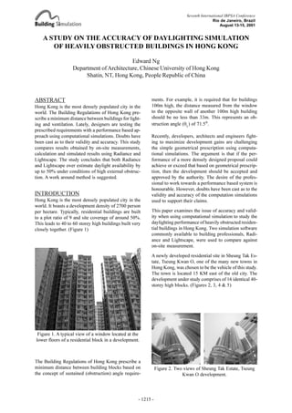
  • 1. A STUDY ON THE ACCURACY OF DAYLIGHTING SIMULATION OF HEAVILY OBSTRCUTED BUILDINGS IN HONG KONG Edward Ng Department ofArchitecture, Chinese University of Hong Kong Shatin, NT, Hong Kong, People Republic of China ABSTRACT Hong Kong is the most densely populated city in the world. The Building Regulations of Hong Kong pre- scribe a minimum distance between buildings for light- ing and ventilation. Lately, designers are testing the prescribed requirements with a performance based ap- proach using computational simulations. Doubts have been cast as to their validity and accuracy. This study compares results obtained by on-site measurements, calculation and simulated results using Radiance and Lightscape. The study concludes that both Radiance and Lightscape over estimate daylight availability by up to 50% under conditions of high external obstruc- tion. A work around method is suggested. INTRODUCTION Hong Kong is the most densely populated city in the world. It boasts a development density of 2700 person per hectare. Typically, residential buildings are built to a plot ratio of 9 and site coverage of around 50%. This leads to 40 to 60 storey high buildings built very closely together. (Figure 1) ments. For example, it is required that for buildings 100m high, the distance measured from the window to the opposite wall of another 100m high building should be no less than 33m. This represents an ob- struction angle (qL ) of 71.5°. Recently, developers, architects and engineers fight- ing to maximize development gains are challenging the simple geometrical prescription using computa- tional simulations. The argument is that if the per- formance of a more densely designed proposal could achieve or exceed that based on geometrical prescrip- tion, then the development should be accepted and approved by the authority. The desire of the profes- sional to work towards a performance based system is honourable. However, doubts have been cast as to the validity and accuracy of the computation simulations used to support their claims. This paper examines the issue of accuracy and valid- ity when using computational simulation to study the daylighting performance of heavily obstructed residen- tial buildings in Hong Kong. Two simulation software commonly available to building professionals, Radi- ance and Lightscape, were used to compare against on-site measurement. A newly developed residential site in Sheung Tak Es- tate, Tseung Kwan O, one of the many new towns in Hong Kong, was chosen to be the vehicle of this study. The town is located 15 KM east of the old city. The development under study comprises of 16 identical 40- storey high blocks. (Figures 2, 3, 4 & 5) Figure 1. A typical view of a window located at the lower floors of a residential block in a development. Figure 2. Two views of Sheung Tak Estate, Tseung Kwan O development. The Building Regulations of Hong Kong prescribe a minimum distance between building blocks based on the concept of sustained (obstruction) angle require- Seventh International IBPSA Conference Rio de Janeiro, Brazil August 13-15, 2001 OBSTRUCTED - 1215 - A Study on the Accuracy of Daylighting Simulation of Heavily Obstructed Buildings in Hong Kong Daylighting and Solar Shading 2 Edward Ng
  • 2. Figure 3. Site Plan of Shueng Tak Estate, TKO. Location of the on-site measurement. Figure 4. Elevation of a typical block of Shueng Tak Estate, TKO. On site measurements obtained in units 714 (Ht=23), 1513 (Ht=45) and 3713 (Ht=104) were used for this paper. Figure 5. Plan of a typical block of Shueng Tak Estate, TKO. On Site measurements obtained in units 714, 1513 and 3713 at the eastern wing of the block were used for this paper. Location of the on-site measurement. SKY CONDITIONS Hong Kong (Latitude 22.3°N, Longitude +114.2°) is located at the south eastern corner of China. Base on Hong Kong Observatory data (1961-1990), Hong Kong‘s climate is sub-tropical, tending towards tem- perate for nearly half the year. Sky conditions in Hong Kong could be typified as Maritime, cloudy with a mean cloud amount of 71% and a mean yearly sunshine fac- tion of 48%. The sky is clearer in the winter and mostly cloudy during the spring. Given the variety and the temporal quality of the sky conditions in Hong Kong, predicting daylight availability accurately for build- ing interiors is difficult. However, for the purpose of building legistlation, the worst case scenario of an over- cast sky may be used. Based on scanned sky luminance data of Singapore sky (Lam et al, 1999), which is similiar to Hong Kong’s sky, the relative error between a cloudy sky and the CIE Standard Overcast Sky is small (Tregenza 1999). Therefore, for the purpose of this study, the CIE Standard Overcast Sky will be as- sumed throughout. ON-SITE MEASUREMENT For this study, 3 residential units at various floor lev- els were measured between June and Oct 2000. Sets of Li-Cor 1400 datalogger and LI-210SA Photometric sensors were used. A photocell was placed on the roof top to record global horizontal illuminance of an un- obstructed sky. Various photocells were placed outside the centre of the window glazing of various residen- tial units to measure vertical illuminance. (Figures 6, 7 & 8) The amount of light received on the vertical surface of the building as a percentage of the unob- structed sky could be devised. The equipment were left to automatically log the data at 5 minute intervals for 10 weeks. To obtain useful data (those collected under an overcast sky conditions), 12 116 23 45 104 Height 0 - 1216 -
  • 3. the following procedures were applied. · Weather reports from the Hong Kong Observatory was used to pin point the cloudy days. · Global horizontal illumination was examined to identify the periods that the sky was fluctuating. A difference in excess of 10% between one data point to another was eliminated. · Periods that Global horizontal illuminance exceed 25 Klx were eliminated. (Figure 9) For highly obstructed urban environment, most of the daylight of the building interiors comes from inter re- flected light. (Figure 10) To account for that in the study, the area weighted average reflectance of the walls opposite the windows were measured using a narrow field (2°) spot luminance meter. A large piece of card- board of known reflectance was used on site to cali- brate against the measurements. A wall elevation 20m x 20m was used to calculate the area weighted aver- age reflectance. (Table 1) This is estimated to be 0.39. To round up the value, 0.4 will be assumed. The sur- faces of the walls were considered sufficiently articu- lated to be considered uniform and diffuse for the model and computational studies. Figure 6. The experimental set up. For the purpose of this paper, only the reading from the photocell on the window was used. Position of photocell looking vertically from the window Figure 7. Plan of a residential unit and location of the photocell.. Figure 10. Reflectances of the building surface ranges from 0.1to 0.45. 0.3 - 0.45 0.1 0.1 - 0.4 0 10000 20000 30000 40000 50000 60000 Time GlobalHoizontalIlluminace Figure 9. An example of the daily variation of Global Horizontal Illuminance : 10am and 2pm. Figure 8. A fish eye lens view of the Photocell located at unit 1513. Table 1. Reflectances of the wall surface Wall Window AreaMean Reflectance 0.42 0.32 67% 33% Data that might be useful - 1217 -
  • 4. CALCULATION The amount of light reaching the interior of a building is the sum of Sky Component (SC), Externally Re- flected Component (ERC) and Internally Reflected Component (IRC). The split flux calculation for Day- light Factor assumed that the light incident on the ver- tical surface of the window is distributed over all the interior surface of the room. Therefore, by knowing Ews , the average Daylight Factor of an interior could be calculated. Let Ew be the illuminance on the win- dow from the sky, the upper and lower angles of ob- struction are fH and fL in section and the right and left angles of obstruction qR and qL in plan: θφφθ θ θ φ φ θφ dddLE H L R L w coscos2 ∫ ∫= Lqf is the luminance of a point in the sky at altitude q and azimuth f. Lz is the zenith luminance (Lz ) of the CIE overcast sky: 3 sin21 θ θφ + = zLL Based on Equations 1 and 2, the illuminance Ews from a CIE overcast sky of zenith luminance is:                   − − − + − ×+ = ) 3 cos2cos2 4 2sin2sin 2 ()sin(sin 3 1 33 LH LH LH RL zws LE θθ θθ θθ φφ Similiarly, the illuminance Ewr from light reflected onto the window opening from surrounding buildings is (Tregenza, 1989): ( )                               − + − ×+− ×× − = ) 4 2sin2sin 2 ( )sin(sin 2 5.01 1 LHLH RL bws b wr E E θθθθ φφ π π ρ ρ The total amount of light reaching the window is there- fore Ews + Ewr . The Average Daylight Factor on the vertical surface of the building is: %100× + = h wswr ws E EE VDF To account for light coming from below the horizon, the following formula could be used: %100 2 ×= h gg wg E E VDF ρ Since ground reflectance is low, it is not worthwhile to calculate Eg /Eh to high accuracy. It is customary to as- sume a value of 0.2 to 0.3 depending on the extent of the external obstruction. 0.2 was used in the calcula- tion. It should be note that the assumption made here has the tendency to unde restimate light coming from the ground for measurements taken at the upper floors of a tall buildings. This is due to the fact that some of the sky will become visible as one goes higher. Since this paper is focused on conditions around the lower floors, it is not worth the effort here to address the point. Taking into account light from above and below the horizon, the Average Vertical Daylight Factor on the building surface is: wgws VDFVDFVDF += COMPUTER SIMULATION The residential development was modeled and simu- lated using Desktop Radiance 3.1.8 and Lightscape v3.2 running on Wintel graphics workstations. The buildings were modelled using a commercially available modelling software. The 3D model (dxf) was imported into Lightscape. Materials with the appro- priate reflectances were assigned. Lightscape does not allow users to select the sky conditions directly. An approximation to CIE Overcast Sky could be achieved by setting Sky conditions to Cloudy, sun illuminance to 0 lx and solar elevation at 90°. For Radiance, CIE Overcast Sky was used. Accuracy was set to High. Ambient Bounces was set to 5. Geometry detail was set to High. Light Variation is Low. Oversampling ra- tio was set to 1x. Four sets of simulations were conducted for both Lightscape and Radiance: reflectance = 0.0, 0.2, 0.4 and 0.6 respectively. (Figures 11, 12, 13 & 14) Illuminance levels of the surface of the particular block at various heights were read off in Lightscape using the Light Analysis function. (Figure 13) For Desktop Radiance, there was no automatic reporting function. Hence Iso-lux contours were plotted against the simu- lated image and readings was scaled off manually. (Fig- ure 14) (1) (2) (3) (4) (5) (6) (7) - 1218 -
  • 5. Figure 11. An example of simulated results using Lightscape. Reflectance of building surfaces is 0.4. Figure 12. An example of simulated results using Radiance. Reflectance of building surfaces is 0.4. Figure 14. An example of simulated results using Radiance. Reflectance of building surfaces is 0.4. Figure 13. An example of simulated results using Lightscape. Reflectance of building surfaces is 0.4. - 1219 -
  • 6. Figure 15. Results of the Experiments and Simulations. Reflectance of building surfaces is 0.4. Table 2. Relative errors between measured results and simulated results 44.1 10.1 6.5 0 5 10 15 20 25 30 35 40 45 50 116 112 108 104 100 96 92 88 84 80 76 72 68 64 60 56 52 48 44 40 36 32 28 24 20 16 12 Height (M) "Vertical"DaylightFactor% LDF (40%) Measurement RDF(40%) Calculation Desktop Radiance Lightscape RESULTS AND ANALYSIS Figure 15 shows the results of the on-site measure- ment, calculation and computational simulations. Ta- ble 2 shows the relative errors between simulated re- sults, calculation and on-site measurements. Table 3. Relative errors between calculated results and simulated results 108 100 Obstruction (degree) Height (m) 92 84 76 68 60 52 44 36 28 0 4.5 13.4 21.8 29.2 35.6 41.3 46.1 50.2 53.7 56.7 20 59.2 Radiance Lightscape +5.1% -1.6% -6.5% -0.9% +5.1% +11.4% +19.7% +27.8% +34.3% +40.4% +45.5% +49.8% -7.5% -22.3% -34.1% -32.2% -27.8% -23.9% -11.2% +0.2% +7.1% +9.3% +15.1% +36% It is noted that at the lower floors, the calculation re- sults match the on-site measurement very closely in- deed. The result is in agreement with previous research findings comparing the calculation method with meas- urements of physical models in an artifical sky. (Ng, 2000) The large error at the upper floor was probably due to the reasons explained earlier. The calculation results largely agree with results ob- tained using Desktop Radiance at higher floors and at obstruction angle less than 30 degree. (Table 3) How- ever, when obstruction angle exceeds 35 degree, er- rors increase. At high obstruction angle of 60 degree, Radiance over-estimate available daylight by approxi- mately 50%. This is a very serious error indeed. Lightscape tends to under-estimate available daylight at low obstruciton angles and over estimate it at high obstruciton angles. Referring to Figure 15, it should be noted that the shapes of the two curves largely follows each other. Results of Lightscape and Radiance differ by around High floor Middle floor Low floor Radiance Lightscape -21.1% +31.7% +47.6% -43.6% +2.9% +22.6% Calculation -22.5% -5.2% -6.5% -80% -60% -40% -20% 0% 20% 40% 60% 116 108 100 92 84 76 68 60 52 44 36 28 20 12 Height (m ) RelativeError Figure 16. Relative errors between Lightscape and Radiance - 1220 -
  • 7. 0 5 10 15 20 25 30 35 40 45 50 116 111 106 101 96 91 86 81 76 71 66 61 56 51 46 41 36 31 26 21 16 Height (M) "Vertical"DaylightFactor% LDF (20%) LDF (60%) RDF (20%) RDF (60%) measurement calculation Radiance (r=0.2) Radiance (r=0.6) Lightscape (r=0.2) Lightscape (r=0.6) 10% to 20% at higher levels and around 50% at lower levels. (Figure 16) To explore the effects of reflectance settings on the simulation results, the measured and calculated results were compared with Lightscape and Radiance results when reflectance were set at 0.2 and 0.6. Figure 17 shows that, for Radiance, the r=0.2 curve provides a better match with the calculated results. In this case Radiance will under eatimate by 10% at the upper lev- els and over estimate by around 25% at lower levels. CONCLUSION With respect to the study which focused on buildings under conditions of high external obstruction typically found in high density urban environment, the follow- ing conclusions could be drawn: · Results of on-site mesurement largely agree with cal- culated results. The method of calculation is devised based on first principles. Although a number of as- sumptions were built into the formulae, the resultant errors were small and were acceptable. · Both Lightscape and Radiance tend to over-estimate daylight availability at lower floor levels (or when the angle of obstruction is high). · Radiance gives more accurate results when the an- gle of obstruction is less than 35 degree. Lightscape is more accurate for obstruction more than 40 degree. · For Radiance, it is possible to work around the er- Figure 17. Results of the Experiments and Simulations. rors by purposefully setting a lower reflectance. It is suggested that a value less than 50% of true value be used. In practice, it will not be a problem when day- light of higher levels are under-estimated. However, it is prudent not to over-estimate daylight at the lower levels. · Although Lightscape is less accurate for higher lev- els (low obstruciton angles), it is surprising to see that it performs very well under conditions of high exter- nal obstruciton. It is suggested that a reflectance around 75% of the true value be used to yield a more con- servative result. FURTHER STUDIES The study is limited in that the on-site measurement refers only to a specific site. Additional sites should be studied to further validate the results here. The study was conducted based on “Vertical Daylight Factor” of the building surfaces. Further studies based on actual daylight factor measurements of building interiors could provide insights into the accuracy of the simulation softwere. It is suggested that a point by point validation of the horizontal working plane at various distance from the window be studied. This study assumes a CIE Overcast Sky. Further stud- ies based on sky models more representative of Hong Kong sky conditions could be conducted. This will be possible when data obtained by the newly constructed International Daylight Monitoring Station at CUHK becomes available. - 1221 -
  • 8. ACKNOWLEDGEMENTS The on site measurement portion of the study was funded by a Technical Service Agreement between CUHK and Anthony Ng Architects Ltd. The author wishes to thank Miss Wu Wei for helping with the simulations, Mr Chan Tak Yan for helping with the model measurements, and Mr Max Lee for coordinat- ing the superiving the on-site measurements. Thanks are due to the following student helpers for the pains- taking task of the on-site measurement: Francis Wong, Belinda Law, Chan Tak Yan, Ricky Chan, Wong Wing Tak. David Cheung, Jacky Choi, Fung Kin Chiu, Leo Cheung and Wu Wei. REFERENCES Hong Kong Observatoy, Summary of Meteorological Observations in Hong Kong 1999, Hong Kong Governemnt Publication Centre, 1999. Tregenza, P. R., Standard skies for maritime climates, Lighting Research and Technology 31(4), 1999. Tregenza, P. R., Modification of the split flux formu- lae for mean daylight factor and internal reflected com- ponent with large external obstructions, Lighting Re- search and Technology 21(3), 1989. Lam, K. P., Mahdavi, A., Ullah, M., Ng, E., Pal, V., Evaluation of Six Sky Luminance rediction Models Using Measured Data from Singapore, Lighting Re- search and Technology 31(1), 1999. Litlefair, P. J. and Lindsay, C. R. T., Scale models and artificial skies in daylighting studies, BEPAC Techni- cal Note TN90/3, Garston: Building Environmental Performance Analysis Club, 1991. Baker, N., Fanchiotti, A. & Steemers, K., Daylighting in Architecture - A European Reference Book, James & James, London, 1993. Ng, E., A simplified daylighting tool for high density urban residential buildings, Lighting Research and Technology, UK. (In Press) NOMENCLATURE Eh Global Horizontal Illuminance (lx) of an un- obstructed sky. Ew Illuminance (lx) due to the hemisphere of the sky and surrounding buildings above the ho- rizon to the vertical window surface. Ews Illuminance (lx) due to the unobstructed sky above the horizon to the vertical window sur- face. Ewr Illuminance (lx) due to the reflections of sur- rounding buildings above the horizon to the vertical window surface. Eg Illuminance (lx) due to the ground and build- ings below the horizon to the vertical window surface. rg Mean ground reflectance. rb Mean reflectance of obstructing buildings. Lz Zenith luminance of the CIE overcast sky. VDFws Vertical Average Daylight Factor due to the upper quadrant of the hemisphere (Sky + Buildings). VDFwg Vertical Average Daylight Factor due to the lower quadrant of the hemisphere (Ground + Buildings). For definitions of fH fL qR and qL see diagram below: φL θL Section Plan θH φR FURTHER INFORMATION Dr Edward Ng, Department of Architecture, Chinese Univercity of Hong Kong, Shatin, NT, Hong Kong, China. Tel: +(852) 2609 6515, Fax: +(852) 2603 5267, Email: edwardng@cuhk.edu.hk, Web: www.edwardng.com. - 1222 -