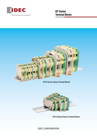
BY1K Screw Clamp Terminal Blocks Guide
•
2 likes•1,007 views

Terminal (cầu đấu) Idec là thiết bị để kết nối dây điện với các thiết bị điều khiển hoặc động lực. Giúp nối liền mạch điện trong hệ thống điện.

Recommended
Recommended
More Related Content
What's hot
What's hot (18)
Similar to BY1K Screw Clamp Terminal Blocks Guide
Similar to BY1K Screw Clamp Terminal Blocks Guide (20)
More from CTY TNHH HẠO PHƯƠNG
More from CTY TNHH HẠO PHƯƠNG (20)
Recently uploaded
Recently uploaded (20)
BY1K Screw Clamp Terminal Blocks Guide
- 1. BY1K Screw Clamp Terminal Blocks BY1S Spring Clamp Terminal Blcoks BY Series Terminal Blocks
- 3. Ratings / Applicable Wires Part No. IEC/EN UL/c-UL Terminal Screw SizeInsulation Voltage Rated Current Wire Size (mm2 ) Solid /Stranded Tightening Torque (N·m) Insulation Voltage Rated Current Wire Size (AWG) Solid/Stranded Tightening Torque (N·m) Standardterminalblock BY1K-2.5N 800V 24A 0.5 to 2.5 0.4 to 0.6 600V 20A 28 to 12 0.56 M2.6 BY1K-4N 800V 32A 0.5 to 4.0 0.5 to 1.0 600V 30A 22 to 10 1.13 M3 BY1K-6N 800V 57A 0.5 to 6.0 0.8 to 1.6 600V 50A 26 to 8 1.58 M4 BY1K-10N 800V 76A 0.5 to 10 1.2 to 2.4 600V 65A 24 to 6 2.15 M4 BY1K-16 1,000V 76A 2.5 to 16 2.0 to 4.0 600V 78A 14 to 4 3.5 M5 BY1K-35 1,000V 125A 4.0 to 35 2.5 to 5.86 1,000V 114A 10 to 2 5.8 M6 BY1K-50 1,000V 150A 16 to 50 4.6 to 6.09 1,000V 150A 6 to 1/0 (Note) 6.0 M6 BY1K-95 1,000V 232A 35 to 95 8.0 to 17.25 1,000V 230A 2 to 4/0 (Note) 16.8 M8 Groundterminalblock BY1K-2.5NPE 0.2 to 2.5 0.46 to 0.6 600V 28 to 12 0.46 to 0.6 M2.6 BY1K-4NPE 0.2 to 4.0 0.6 to 0.7 600V 26 to 10 0.6 to 0.7 M3 BY1K-6NPE 0.2 to 6.0 1.15 to 1.6 600V 26 to 8 1.15 to 1.6 M3.5 BY1K-10NPE 0.2 to 10 1.5 to 1.8 600V 24 to 6 1.5 to 1.8 M4 BY1K-16PE 2.5 to 16 2.07 to 4.02 14 to 6 4.0 M5 BY1K-35PE 4.0 to 35 2.5 to 5.86 10 to 2 6.2 M6 BY1K-50PE 16 to 50 6.09 to 8.05 6 to 1/0 (Note) 6.1 M6 BY1K-95PE 35 to 95 6.9 to 10.35 2 to 4/0 (Note) 12.0 M8 Note: Stranded wire only Compact European Style Terminal Blocks! Material Parts Name Material (Coating) Housing Polyamide (UL94V-0) Bus bar Copper alloy (Tin coated) Screw Steel (Zinc plated trivalent chromate) Cage clamp Steel (Zinc plated trivalent chromate) Ground contact bracket (Ground terminal blocks only) Copper alloy (Tin coated) Ground support bracket (Ground terminal blocks only) Steel (Zinc plated trivalent chromate) • Mounting space reduced by 50% compared to conventional products. • Wide variety to choose from. Standard and ground terminal blocks available. • Various wire sizes can be connected. • Simple wire connection. Easy expansion of terminal blocks. • Easy ground connection to DIN rail (ground terminal block). • Mounts on a 35-mm-wide DIN rail. • UL/c-UL recognized and EN compliant. Applicable Standards Mark Certification Organization/File No. UL1059 CSA C22.2 No.158 UL/c-UL Recognition File No. E78117 IEC/EN60947-7-1 (Standard terminal block) IEC/EN60947-7-2 (Ground terminal block) EU Low Voltage Directive General Ratings Dielectric Strength (Note) 2500V AC, 1 minute Insulation Resistance (Note) 2000MΩ minimum (500V DC megger) Vibration Resistance Frequency: 5 to 55 Hz Amplitude: 0.5 mm Shock Resistance 1000m/s2 Operating Temperature –25 to +55°C (no freezing) Storage Temperature –25 to +70°C (no freezing) Operating Humidity 45 to 85% RH (no condensation) Note: Except ground terminal blocks. PE Terminal Jumper terminal (screw) PE function ground terminal Standard terminal block Part No. Internal Connection BY1K-2.5N BY1K-4N BY1K-6N BY1K-10N BY1K-16 BY1K-35 BY1K-50 BY1K-95 Ground terminal block Part No. Internal Connection BY1K-2.5NPE BY1K-4NPE BY1K-6NPE BY1K-10NPE BY1K-16PE BY1K-35PE BY1K-50PE BY1K-95PE PE 2 BY1K Screw Clamp Terminal Blocks
- 4. Screw Clamp Terminal Blocks All dimensions in mm. Standardterminalblock Part No. BY1K-2.5N BY1K-4N BY1K-6N Appearance / Dimensions See page 2 for internal connection diagram Width: 5.1 mm Weight: Approx. 6.2g Width: 6.1 mm Weight: Approx. 7.2g Width: 8 mm Weight: Approx. 13.4g 2.7 45.8 35.9 42.85.1 3.8 30.5 15.7 DIN Rail WhenusingDINRail:47.0 M2.6 terminal screw (slotted) 35.9 42.8 3.7 6.1 3.8 45.8 30.5 15.7 DIN Rail WhenusingDINRail:47.0 M3 terminal screw (slotted) 45.8 4.8 8.0 6.7 42.8 18.8 28.2 35.9 DIN Rail WhenusingDINRail:47.0 M4 terminal screw (slotted) Ordering No. BY1K-2.5N BY1K-4N BY1K-6N Package Quantity 100 100 50 Groundterminalblock Part No. BY1K-2.5NPE BY1K-4NPE BY1K-6NPE Appearance / Dimensions See page 2 for internal connection diagram Width: 5.2 mm Weight: Approx. 16.2g Width: 6.2 mm Weight: Approx. 18.8g Width: 8.2 mm Weight: Approx. 26.4g 26.9 45.3 2.6 5.2 4.0 15.7 35.9 42.8 DIN Rail (BAP) WhenusingDINRail:47.0 M2.6 terminal screw (slotted) M2.6 mounting screw (slotted) 45.3 3.3 6.2 4.0 15.7 35.9 42.8 26.9 DIN Rail (BAP) WhenusingDINRail:47.0 M3 terminal screw (slotted) M3 mounting screw (slotted) 18.8 39.5 42.8 27.9 45.3 8.2 4.5 4.6 DIN Rail (BAP) WhenusingDINRail:47.0 M3.5 terminal screw (slotted) M4 mounting screw (slotted) Ordering No. BY1K-2.5NPE BY1K-4NPE BY1K-6NPE Package Quantity 100 100 50 Standards IEC/EN UL/c-UL IEC/EN UL/c-UL IEC/EN UL/c-UL Specification/Ratings Insulation Voltage 800V (Note 1) 600V 800V (Note 1) 600V 800V (Note 1) 600V Wire Size (Solid/ Stranded ) Standard terminal block 0.5 to 2.5mm2 28 to 12AWG 0.5 to 4.0mm2 22 to 10AWG 0.5 to 6.0mm2 26 to 8AWG Ground terminal block 0.2 to 2.5mm2 28 to 12AWG 0.2 to 4.0mm2 26 to 10AWG 0.2 to 6.0mm2 26 to 8AWG Rated Current (Note 1) 24A 20A 32A 30A 57A 50A Terminal Screw Size M2.6 M3 Standard terminal block: M4 Ground terminal block: M3.5 Tightening torque Standard terminal block 0.4 to 0.6 N·m 0.56 N·m 0.5 to 1.0 N·m 1.13 N·m 0.8 to 1.6 N·m 1.58 N·m Ground terminal block 0.46 to 0.6 N·m 0.46 to 0.6 N·m 0.6 to 0.7 N·m 0.6 to 0.7 N·m 1.15 to 1.6 N·m 1.15 to 1.6 N·m Recommended Wire Strip Length 8 to 10mm 8 to 10mm 10 to 12mm Accessories End Stop BY9Z-KEW35/2 End Plate (Note 1) BY9Z-KEP6 Marking Strip BY9Z-W5, BY9Z-W5Z-, BY9Z-W5K- BY9Z-W6, BY9Z-W6Z-, BY9Z-W6K- DIN Rail (Note 2) BAA1000 (Aluminum), BAP1000 (Steel) Jumper (2,3,4,10 Pole) (Note 3) BY9Z-KQV-2.5/2, BY9Z-KQV-2.5/3 BY9Z-KQV-2.5/4, BY9Z-KQV-2.5/10 BY9Z-KQV-4/2, BY9Z-KQV-4/3 BY9Z-KQV-4/4, BY9Z-KQV-4/10 BY9Z-KQV-6/2, BY9Z-KQV-6/3 BY9Z-KQV-6/4, BY9Z-KQV-6/10 Note 1: Except ground terminal blocks. Note 2: Use BAP1000 (steel) for ground terminal blocks. Note 3: Cannot be used on ground terminal blocks. 3 BY1K Screw Clamp Termina Blocks
- 5. Screw Clamp Terminal Blocks All dimensions in mm. Standardterminalblock Part No. BY1K-10N BY1K-16 BY1K-35 Appearance / Dimensions See page 2 for internal connection diagram Width: 10.0 mm Weight: Approx. 17.6g Width: 12.0 mm Weight: Approx. 31.8g Width: 16.0 mm Weight: Approx. 49.4g 45.8 28.2 6.8 10.0 6.7 42.8 35.9 18.8 DIN Rail WhenusingDINRail:47.0 M4 terminal screw (slotted) 62.5 56.5 33.6 7.8 7.3 12.0 24.4 60.0 DIN Rail WhenusingDINRail:63.3 M5 terminal screw (slotted) 10.2 16.0 10.1 24.4 56.5 62.5 35.6 60.0 DIN Rail WhenusingDINRail:63.3 M6 terminal screw (slotted) Ordering No. BY1K-10N BY1K-16 BY1K-35 Package Quantity 50 50 25 Groundterminalblock Part No. BY1K-10NPE BY1K-16PE BY1K-35PE Appearance / Dimensions See page 2 for internal connection diagram Width: 10.2 mm Weight: Approx. 30.1g Width: 12.2 mm Weight: Approx. 54g Width: 16 mm Weight: Approx. 76.6g 18.8 39.5 42.8 45.3 27.9 10.2 5.6 5.5 DIN Rail (BAP) WhenusingDINRail:47.0 M4 terminal screw (slotted) M4 mounting screw (slotted) 56.6 8.0 7.3 12.2 61.1 33.5 24.4 DIN Rail (BAP) WhenusingDINRail:63.0 M5 terminal screw (slotted) M3 mounting screw (slotted) 56.6 61.1 10.3 10.2 16.0 33.5 24.4 DIN Rail (BAP) WhenusingDINRail:63.0 M6 terminal screw (slotted) M3 mounting screw (slotted) Ordering No. BY1K-10NPE BY1K-16PE BY1K-35PE Package Quantity 50 50 25 Standards IEC/EN UL/c-UL IEC/EN UL/c-UL IEC/EN UL/c-UL Specification/Ratings Insulation Voltage 800V (Note 1) 600V 1,000V (Note 1) 600V (Note 1) 1,000V (Note 1) 1,000V (Note 1) Wire Size (Solid/ Stranded ) Standard terminal block 0.5 to 10 mm2 24 to 6AWG 2.5 to 16 mm2 14 to 4AWG 4.0 to 35 mm2 10 to 2AWG Ground terminal block 0.2 to 10 mm2 24 to 6AWG 2.5 to 16 mm2 14 to 6AWG 4.0 to 35 mm2 10 to 2AWG Rated Current (Note 1) 76A 65A 76A 78A 125A 114A Terminal Screw Size M4 M5 M6 Tightening Torque Standard terminal block 1.2 to 2.4 N·m 2.15 N·m 2.0 to 4.0 N·m 3.5 N·m 2.5 to 5.86 N·m 5.8 N·m Ground terminal block 1.5 to 1.8 N·m 1.5 to 1.8 N·m 2.07 to 4.02 N·m 4.0 N·m 2.5 to 5.86 N·m 6.2 N·m Recommended Wire Strip Length 10 to 12 mm 15 to 17 mm 16 to 18 mm Accessories End Stop BY9Z-KEW35/2 BY9Z-KEW35/1 End Plate (Note 1) BY9Z-KEP6 BY9Z-KEP2 Marking Strip BY9Z-W6, BY9Z-W6Z-, BY9Z-W6K- BY9Z-W6, BY9Z-W6Z-, BY9Z-W6K- BY9Z-W8, BY9Z-W8Z-, BY9Z-W8K- DIN Rail (Note 2) BAA1000 (Aluminum), BAP1000 (Steel) Jumper (2,3,4,10 Pole) (Note 3) BY9Z-KQV-10/2, BY9Z-KQV-10/3 BY9Z-KQV-10/4, BY9Z-KQV-10/10 BY9Z-KQV-16/2, BY9Z-KQV-16/3 BY9Z-KQV-16/4 BY9Z-KQV-35/2, BY9Z-KQV-35/3 BY9Z-KQV-35/4 Note 1: Except ground terminal blocks. Note 2: Use BAP1000 (steel) for ground terminal blocks. Note 3: Cannot be used on ground terminal blocks. 4 BY1K Screw Clamp Termina Blocks
- 6. Screw Clamp Terminal Blocks Standardterminalblock Part No. BY1K-50 BY1K-95 Appearance / Dimensions See page 2 for internal connection diagram Width: 20.0 mm Weight: Approx. 106g Width: 25.0 mm Weight: Approx. 184.6g 12.8 20.0 27.0 13.5 70.5 6.5 74.4 41.0 32.5 DIN Rail WhenusingDINRail:76.0 M6 terminal screw (Hexagon socket head cap) 80.0 88.3 16.8 25.0 32.0 19.6 48.7 38.0 6.5 DIN Rail WhenusingDINRail:90.0 M8 terminal screw (Hexagon socket head cap) Ordering No. BY1K-50 BY1K-95 Package Quantity 10 10 Groundterminalblock Part No. BY1K-50PE BY1K-95PE Appearance / Dimensions See page 2 for internal connection diagram Width: 20.0 mm Weight: Approx. 170.9g Width: 25.0 mm Weight: Approx. 278g M6 mounting screw (cross recessed head + slotted head) 70.5 40.0 70.0 12.8 20.0 27.0 12.3 WhenusingDINRail:75.8 32.5 M6 terminal screw (Hexagon socket head cap) DIN Rail (BAP) 16.3 25.0 32.0 19.8 80.0 82.6 38.0 49.0 WhenusingDINRail:90.0 DIN Rail (BAP) M6 mounting screw (cross recessed head + slotted head) M8 terminal screw (Hexagon socket head cap) Ordering No. BY1K-50PE BY1K-95PE Package Quantity 10 10 Standards IEC/EN UL/c-UL IEC/EN UL/c-UL Specification/Ratings Insulation Voltage 1,000V 1,000V 1,000V 1,000V Wire Size (Solid/ Stranded ) Standard terminal block 16 to 50 mm2 6 to 1/0AWG (Stranded wire only) 35 to 95 mm2 2 to 4/0AWG (Stranded wire only) Ground terminal block 16 to 50 mm2 6 to 1/0AWG (Stranded wire only) 35 to 95 mm2 2 to 4/0AWG (Stranded wire only) Rated Current (Note 1) 150A 150A 232A 230A Terminal Screw Size M6 M8 Tightening torque Standard terminal block 4.6 to 6.09 N·m 6.0 N·m 8.0 to 17.25 N·m 16.8 N·m Ground terminal block 6.09 to 8.05 N·m 6.1 N·m 6.9 to 10.35 N·m 12.0 N·m Recommended Wire Strip Length 20 to 25 mm Standard terminal block: 30 to 35 mm Ground terminal block: 25 to 30 mm Accessories End Stop BY9Z-KEW35/1 End Plate (Note 1) — Marking Strip BY9Z-W6, BY9Z-W6Z-, BY9Z-W6K-, BY9Z-W8, BY9Z-W8Z-, BY9Z-W8K- DIN Rail (Note 2) BAA1000 (Aluminum), BAP1000 (Steel) Jumper (2,3 Pole) (Note 3) BY9Z-KQV-50/2, BY9Z-KQV-50/3 — Note 1: Except ground terminal blocks. Note 2: Use BAP1000 (steel) for ground terminal blocks. Note 3: Cannot be used on ground terminal blocks. 5 BY1K Screw Clamp Termina Blocks
- 7. Easy wiring with just one screwdriver. Spring clamp connections promote reduced wiring time. • Spring clamp terminal blocks ensure high contact reliability with different wire shapes and sizes. • Standard and ground terminal blocks mounts on 35 mm DIN rail allowing easy ground connection. • Simply remove the wire insulation for wiring. No need to install crimping terminals or solder wires. One screwdriver can remove and install wires. • High vibration resistance. • Reduces wiring time and maintenance compared to screw clamp terminal blocks. No need to control torque. • UL/c-UL recognized and EN compliant Applicable Standards Mark Certification Organization/File No. UL1059 CSA C22.2 No.158 UL/c-UL Recognition File No. E78117 IEC/EN60947-7-1 (Standard terminal block) IEC/EN60947-7-2 (Ground terminal block) EU Low Voltage Directive General Ratings Dielectric Strength (Note) 2500V AC, 1 minute Insulation Resistance (Note) 2000MΩ minimum (500V DC megger) Vibration Resistance Frequency: 5 to 55 Hz Amplitude: 0.5 mm Shock Resistance 1000m/s2 Operating Temperature –25 to +55°C (no freezing) Storage Temperature –25 to +70°C (no freezing) Operating Humidity 45 to 85% RH (no condensation) Note: Except ground terminal blocks. Material Parts Name Material (Coating) Housing Polyamide (UL94V-0) Bus bar Copper alloy (Tin coated) Ground contact bracket (Ground terminal blocks only) Copper alloy (Tin coated) Spring clamp Stainless steel Ratings / Applicable Wires Terminal Block Part No. IEC/EN UL/c-UL Insulation Voltage Rated Current Wire Size (mm2 ) Solid / Stranded Insulation Voltage Rated Current Wire Size (AWG) Solid / Stranded Standard Terminal Block BY1S-2.5 600V 24A 0.2 to 2.5 600V 18A 28 to 12 BY1S-4 800V 32A 0.2 to 4.0 600V 20A 28 to 12 BY1S-6 800V 41A 0.2 to 6.0 600V 30A 24 to 10 BY1S-10 800V 57A 0.2 to 10 600V 38A 24 to 8 Ground Terminal Block BY1S-2.5PE 0.2 to 2.5 28 to 12 BY1S-4PE 0.2 to 4.0 28 to 12 BY1S-6PE 0.2 to 6.0 24 to 10 BY1S-10PE 0.2 to 10 24 to 8 Internal Connection Standard terminal block Ground terminal block Part No. Internal Connection Part No. Internal Connection BY1S-2.5 BY1S-2.5PE BY1S-4 BY1S-4PE BY1S-6 BY1S-6PE BY1S-10 BY1S-10PE PE PE Socket terminal for jumper PE function ground terminal Terminal BY1S Spring Clamp Terminal Blocks 6
- 8. Spring Clamp Terminal Blocks All dimensions in mm Standardterminalblock Part No. BY1S-2.5 BY1S-4 BY1S-6 BY1S-10 Appearance / Dimensions See page 6 for internal connection diagram Width: 5.0 mm Weight: Approx. 5.6g Width: 6.0 mm Weight: Approx. 8.2g Width: 8.0 mm Weight: Approx. 16g Width: 10.0 mm Weight: Approx. 23.6g 5.0 32.4 38.6 ø4.2 32.2 52.9 When using DIN Rail: 35.3 DIN Rail 6.0 59.0 42.6 ø5.1 36.3 33.1 When using DIN Rail: 35.9 DIN Rail 73.7 8.0 51.0 37.5 44.8 ø6.8 When using DIN Rail: 40.4 DIN Rail 76.6 10.0 41.8 54.5 45.2 ø8.7 When using DIN Rail: 42.3 DIN Rail Ordering No. BY1S-2.5 BY1S-4 BY1S-6 BY1S-10 Package Quantity 50 50 50 50 GroundGroundterminalblock Part No. BY1S-2.5PE BY1S-4PE BY1S-6PE BY1S-10PE Appearance/ Dimensions See page 6 for internal connection diagram Width: 5.0 mm Weight: Approx. 8.2g Width: 6.0 mm Weight: Approx. 11g Width: 8.0 mm Weight: Approx. 20.4g Width: 10.0 mm Weight: Approx. 31.2g 38.6 52.9 32.4 32.2 5.0 ø4.2 When using DIN Rail: 35.3 DIN Rail (BAP) 59.0 42.6 36.3 33.1 6.0 ø5.1 When using DIN Rail: 35.9 DIN Rail (BAP) 73.7 8.0 51.0 37.5 44.8 ø6.8 When using DIN Rail: 40.4 DIN Rail (BAP) 76.6 10.0 41.8 54.5 45.2 ø8.7 When using DIN Rail: 42.3 DIN Rail (BAP) Ordering No. BY1S-2.5PE BY1S-4PE BY1S-6PE BY1S-10PE Package Quantity 50 50 50 50 Standards IEC/EN UL/c-UL IEC/EN UL/c-UL IEC/EN UL/c-UL IEC/EN UL/c-UL Specification/Ratings Insulation Voltage (Note 1) 600V 600V 800V 600V 800V 600V 800V 600V Wire Size 0.2 to 2.5 mm2 28 to 12AWG 0.2 to 4 mm2 28 to 12AWG 0.2 to 6 mm2 24 to 10AWG 0.2 to 10 mm2 24 to 8AWG Rated Current (Note 1) 24A 18A 32A 20A 41A 30A 57A 38A Recommended Wire Strip Length 8 to 9 mm 9 to 10 mm 12 to 13 mm 15 to 16 mm Accessories End Stop BY9Z-SEW35 End Plate BY9Z-SEP1 BY9Z-SEP4 BY9Z-SEP7 BY9Z-SEP9 Marking Strip BY9Z-W5, BY9Z-W5Z- BY9Z-W5K- BY9Z-W6, BY9Z-W6Z-, BY9Z-W6K- DIN rail (Note 2) BAA1000 (Aluminum), BAP1000 (Steel) Jumper (2, 3 Pole) (Note 3) BY9Z-SQV-2.5/2 BY9Z-SQV-2.5/3 BY9Z-SQV-4/2 BY9Z-SQV-4/3 BY9Z-SQV-6/2 BY9Z-SQV-6/3 BY9Z-SQV-10/2 BY9Z-SQV-10/3 Note 1: Except ground terminal blocks. Note 2: Use BAP1000 (steel) for ground terminal blocks. Note 3: Cannot be used on ground terminal blocks. BY1S Spring Clamp Termina Blocks 7
- 9. End Stop Appearance Part No. (Ordering No.) Applicable Terminal Block (Part No.) Package Quantity Dimensions Remarks BY9Z-KEW35/2 BY1K-2.5N, BY1K-2.5NPE BY1K-4N, BY1K-4NPE BY1K-6N, BY1K-6NPE BY1K-10N, BY1K-10NPE 50 8.0 47.0 56.0 M3 (slotted) • Material Housing: Polyamide (UL94V-0) Brackets, Screw: Steel (Zinc plated trivalent chromate) • Weight: Approx. 15.3g BY9Z-KEW35/1 BY1K-16, BY1K-16PE BY1K-35, BY1K-35PE BY1K-50, BY1K-50PE BY1K-95, BY1K-95PE 50 M4 (slotted) 63.0 12.0 56.0 • Material Housing: Polyamide (UL94V-0) Brackets, Screw: Steel (Zinc plated trivalent chromate) • Weight: Approx. 31.3g BY9Z-SEW35 BY1S-2.5, BY1S-2.5PE BY1S-4, BY1S-4PE BY1S-6, BY1S-6PE BY1S-10, BY1S-10PE 50 40.2 6.0 55.0 • Material Housing: Polyamide (UL94V-0) Brackets: Stainless • Weight: Approx. 7.7g End Plate Appearance Part No. (Ordering No.) Applicable Terminal Block (Part No.) Package Quantity Dimensions Remarks BY9Z-KEP2 BY1K-16, BY1K-35 100 56.5 1.5 51.3 • Material: Polyamide (UL94V-0) • Weight: Approx. 4.8g BY9Z-KEP6 BY1K-2.5N, BY1K-4N BY1K-6N, BY1K-10N 100 40.6 36.0 1.5 • Material: Polyamide (UL94V-0) • Weight: Approx. 2.2g BY9Z-SEP1 BY1S-2.5, BY1S-2.5PE 100 52.9 21.2 1.5 • Material: Polyamide (UL94V-0) • Weight: Approx. 1.9g BY9Z-SEP4 BY1S-4, BY1S-4PE 100 1.5 59.0 21.9 • Material: Polyamide (UL94V-0) • Weight: Approx. 2.2g BY9Z-SEP7 BY1S-6, BY1S-6PE 100 26.3 73.7 1.5 • Material: Polyamide (UL94V-0) • Weight: Approx. 3.2g BY9Z-SEP9 BY1S-10, BY1S-10PE 100 76.6 28.5 1.5 • Material: Polyamide (UL94V-0) • Weight: Approx. 3.7g 8 BY Series Terminal Blocks (Accessories)
- 10. Jumpers Appearance Poles Part No. (Ordering No.) Applicable Terminal Block (Part No.) Maximum Current (Note) Package Quantity Dimensions Image: BY9Z-KQV-2.5/3 Image: BY9Z-KQV-50/3 • Material Insulation housing: Polyamide (UL94V-0) Bus bar: Copper alloy (Tin coated) Screw: Steel (Zinc plated trivalentchromate) 2 BY9Z-KQV-2.5/2 BY1K-2.5N 32A 100 Length A 2 Poles: 8.9 Weight:Approx. 1.5g 3 Poles: 14.0 Weight:Approx. 2.4g 4 Poles: 19.1 Weight:Approx. 3.2g 10 Poles: 49.7 Weight:Approx. 8.1g5.1 A 3.8 M2.6 (slotted) 7.13 BY9Z-KQV-2.5/3 4 BY9Z-KQV-2.5/4 10 BY9Z-KQV-2.5/10 2 BY9Z-KQV-4/2 BY1K-4N 41A 100 Length A 2 Poles: 10.5 Weight:Approx. 2.4g 3 Poles: 16.6 Weight:Approx. 3.7g 4 Poles: 22.7 Weight:Approx. 4.8g 10 Poles: 59.3 Weight:Approx. 12.7g 18.0 6.1 M3 (slotted) 7.5A 4.4 3 BY9Z-KQV-4/3 32A4 BY9Z-KQV-4/4 10 BY9Z-KQV-4/10 2 BY9Z-KQV-6/2 BY1K-6N 50A 100 Length A 2 Poles: 14.5 Weight:Approx. 3.3g 3 Poles: 22.5 Weight:Approx. 5.0g 4 Poles: 30.5 Weight:Approx. 6.8g 10 Poles: 78.5 Weight:Approx. 17.7g M3 (slotted) 18.0 7.7 8.0 A 6.3 3 BY9Z-KQV-6/3 4 BY9Z-KQV-6/4 10 BY9Z-KQV-6/10 50 2 BY9Z-KQV-10/2 BY1K-10N 57A 100 Length A 2 Poles: 17.0 Weight:Approx. 3.7g 3 Poles: 27.0 Weight:Approx. 5.7g 4 Poles: 37.0 Weight:Approx. 7.4g 10 Poles: 97.0 Weight:Approx. 19.7g 18.5 7.6A 7.0 10.0 M3 (slotted) 3 BY9Z-KQV-10/3 4 BY9Z-KQV-10/4 10 BY9Z-KQV-10/10 50 2 BY9Z-KQV-16/2 BY1K-16 85A 50 A Length A 2 Poles: 21.6 Weight:Approx. 9.0g 3 Poles: 33.6 Weight:Approx. 13.5g 4 Poles: 45.6 Weight:Approx. 18.1g 27.0 10.2 12.0 M4 (slotted) 9.6 3 BY9Z-KQV-16/3 76A 4 BY9Z-KQV-16/4 2 BY9Z-KQV-35/2 BY1K-35 138A 50 M4 (slotted) A 26.8 8.8 16.0 11.0 Length A 2 Poles: 28.8 Weight:Approx. 13.1g 3 Poles: 44.8 Weight:Approx. 19.8g 4 Poles: 60.8 Weight:Approx. 26.6g 3 BY9Z-KQV-35/3 112A 4 BY9Z-KQV-35/4 25 2 BY9Z-KQV-50/2 BY1K-50 150A 25 3.0 A 20.0 10.0 10.0 20.4 M6 (slotted) Length A 2 Poles: 32.0 Weight:Approx. 25.7g 3 Poles: 52.0 Weight:Approx. 39.8g 3 BY9Z-KQV-50/3 • Material Insulation housing: Polyamide (UL94V-0) Bus bar: Copper alloy (Tin coated) 2 BY9Z-SQV-2.5/2 BY1S-2.5 24A 100 A 5.0 2.8 27.3 2.8 Length A 2 Poles: 9.0 Weight:Approx. 1.2g 3 Poles: 14.0 Weight:Approx. 1.9g 3 BY9Z-SQV-2.5/3 2 BY9Z-SQV-4/2 BY1S-4 32A 100 Length A 2 Poles: 10.85 Weight:Approx. 2.0g 3 Poles: 16.90 Weight:Approx. 3.2g A 2.8 6.0 31.3 3.8 3 BY9Z-SQV-4/3 2 BY9Z-SQV-6/2 BY1S-6 41A 100 Length A 2 Poles: 14.65 Weight:Approx. 3.3g 3 Poles: 22.70 Weight:Approx. 5.1g A 2.8 8.0 34.0 5.6 3 BY9Z-SQV-6/3 Note: Make sure that the total current to the jumper does not exceed the maximum current of each model. Image: BY9Z-SQV-2.5/3 9 BY Series Terminal Blocks (Accessories)
- 11. Jumpers Appearance Poles Part No. (Ordering No.) Applicable Terminal Block (Part No.) Maximum Rated Current (Note) Package Quantity Dimensions Image: BY9Z-SQV-10/2 • Material Insulation housing: Polyamide (UL94V-0) Bus bar: Copper alloy (Tin coated) 2 BY9Z-SQV-10/2 BY1S-10 57A 100 Length A 2 Poles: 16.2 Weight:Approx.4.7g 3 Poles: 26.2 Weight:Approx.7.4g 4.0 A 10.0 27.0 6.2 3 BY9Z-SQV-10/3 Note: Make sure that the total current to the jumper does not exceed the maximum current of each model. DIN Rails (35mm-wide) Specify Ordering No. when ordering DIN rails. Part No. Ordering No. Material Length Weight Package Quantity Remarks BAA1000 BAA1000PN10 Aluminum 1000 mm Approx. 200g 1 set (10) For standard terminal blocks BAP1000 BAP1000PN10 Steel 1000 mm Approx. 320g 1 set (10) For standard and ground terminal blocks Marking Strip Appearance / Dimensions Part No. (Ordering No.) Applicable Terminal Block (Part No.) Package Quantity Remarks Dimensions •Material: Polyamide (UL94V-0) • Weight: 4.7g (per strip) BY9Z-W5 BY1K-2.5N, BY1K-2.5NPE BY1S-2.5, BY1S-2.5PE 50 Blank — BY9Z-W5Z-1/50 Numbers 1 to 50 Horizontal print 4.9 5.9 23BY9Z-W5Z-51/100 Numbers 51 to 100 BY9Z-W5K-1/50 Numbers 1 to 50 Vertical print 4.9 5.9 23 BY9Z-W5K-51/100 Numbers 51 to 100 • Material: Polyamide (UL94V-0) • Weight: 5.6g (per strip) BY9Z-W6 BY1K-4N, BY1K-4NPE BY1K-6N, BY1K-6NPE BY1K-10N, BY1K-10NPE BY1K-16, BY1K-16PE BY1K-35, BY1K-35PE BY1K-50, BY1K-50PE BY1K-95, BY1K-95PE BY1S-4, BY1S-4PE BY1S-6, BY1S-6PE BY1S-10, BY1S-10PE 50 Blank — BY9Z-W6Z-1/50 Numbers 1 to 50 Horizontal print 5.9 5.9 23BY9Z-W6Z-51/100 Numbers 51 to 100 BY9Z-W6K-1/50 Numbers 1 to 50 Vertical print BY9Z-W6K-51/100 Numbers 51 to 100 • Material: Polyamide UL94V-0) • Weight: 6.1g (per strip) BY9Z-W8 BY1K-16, BY1K-16PE BY1K-35, BY1K-35PE BY1K-50, BY1K-50PE BY1K-95, BY1K-95PE 25 Blank — BY9Z-W8Z-1/40 Numbers 1 to 40 Horizontal print 5.9 12.0 23 BY9Z-W8Z-41/80 Numbers 41 to 80 BY9Z-W8K-1/40 Numbers 1 to 40 Vertical print 5.9 12.0 23 BY9Z-W8K-41/80 Numbers 41 to 80 20 19 18 17 16 15 14 13 12 11 10 9 8 7 6 5 4 3 2 1 50 49 48 47 46 45 44 43 42 4131 32 33 34 35 36 37 38 39 4030 29 28 27 26 25 24 23 21 22 Vertical print (numbers 1 to 50) 1 98765432 10 20 30 40 50 19 29 39 49 18 28 38 48 17 27 37 47 16 26 36 46 15 25 35 45 14 24 34 44 13 23 33 43 12 22 32 42 11 21 31 41 Horizontal print (numbers 1 to 50) 57.8 58.3 2.6 57.8 68.3 2.6 5.9 5.9 23 64.0 71.6 2.6 10 BY Series Terminal Blocks (Accessories)
- 12. Use the formula below to calculate the length of the DIN rail and mounting centers. BAA and BAP DIN rails L1 (rail length)= 12.5 × N L2 (mounting centers)= L1 – 25 N = (A+0.1)×n+B+C 12.5 Note: However, N is the rounded up numerical number from the calculated value of N. (Example: N for 19.1 is 20) A: Thickness of each terminal block B: Thickness of end plate C: Thickness of end stop when using 2 pieces of: BY9Z-SEW35 = 53.0 mm BY9Z-KEW35/2 = 55.0 mm BY9Z-KEW35/1 = 59.0 mm n: The number of terminal blocks Notes • This formula is for calculating the maximum rail length includ- ing tolerance. Depending on the combination of terminal blocks, the required rail length may be shorter than the calculated value, particularly when many terminal blocks are combined. • When mounting BY1K-50 or BY1K-50PE with BY1K-95 or BY1K- 95PE next to each other, cut off the protruding part of BY1K-50 and BY1K-50PE using nippers. Cut off the protruding part using nippers BY1K BY1K-2.5N BY1K-4N BY9Z-KEP6 BY1K-6N BY1K-10N BY1K-2.5NPE BY1K-4NPE BY1K-6NPE BY1K-10NPE BY1K-95 BY1K-95PE End Stop BY1K-35PE BY9Z-KEP2 BY1K-50 BY1K-50PE BY1K-16PE BY1K-35 BY1K-16 5.1 6.1 8.0 10.0 16.0 12.0 20.0 25.0 12.2 16.0 1.5 L2 (mounting centers) L1 (rail length) 10.28.2 6.2 5.2 1.5 End Stop BY1S BY1S-6 BY1S-6PE BY9Z-SEP9 BY1S-10PE BY1S-10 BY9Z-SEP7 BY1S-2.5 End Stop End Stop BY1S-2.5PE BY9Z-SEP1 BY1S-4 BY1S-4PE BY9Z-SEP4 5.0 5.0 1.5 6.0 6.0 1.5 8.0 8.0 1.5 10.0 10.0 1.5 L2 (mounting centers) L1 (rail length) Calculating DIN Rail Lengths and Mounting Centers All dimensions in mm. 11 BY Series Terminal Blocks (Accessories)
- 13. • Remove power to the terminal blocks before starting installation, removal, wiring, maintenance, and inspection of the products. Failure to remove power may cause electrical shock, fire, or malfunction. • For wiring, use wires of proper size to meet voltage and current requirements. • Make sure that terminal blocks and wires are connected securely. Otherwise, abnormal heat may be generated and cause fire. • Make sure that cut wire ends and chipping from drilling do not enter into the inside of the product at the time of installation and wiring. Cut wire ends and chipping inside the product may cause fires, failures, and poor conductivity. • Make sure to use under the voltage and electric current suitable for terminal blocks. Using under incorrect voltage and electric current may cause fires and failures. • Do not apply excessive load or shock to the terminal block. Other- wise damages may occur. • Do not apply excessive shock to the connected wires. Otherwise, terminal blocks may be damaged and cause conduction failure. • Do not use in places where the terminal blocks are subject to salt contaminated water, oil, and chemicals. DIN Rail Mounting • Use 35mm-wide DIN rail (BAA1000 or BAP1000) when mounting BY1K or BY1S standard terminal blocks. • When the BY1K and BY1S ground terminal blocks are mounted on the 35mm-wide DIN rail, the conductive metal inside the terminal blocks will come in direct contact with the DIN rail, enabling easy ground connection. Therefore, make sure that the DIN rail is made of steel (BAP1000). Mounting on alumite coated DIN rail (BAA1000) may cause poor conductivity. Contact part Contact part Conductive metal DIN rail (steel) • BY1K and BY1S ground terminal blocks can be used as a protective conductor (PE function) by connecting to a 35mm-wide steel DIN rail (BAP1000) but cannot be used as a PEN function conductor. • See page 2 for BY1K internal connection diagram. See page 6 for BY1S internal connection diagram. Installation BY1K and BY1S Standard Terminal Blocks BY1S Ground Terminal Block • Install the end stop on one side of the DIN rail. • Install the terminal block to the DIN rail, ensuring there is no gap. To install the terminal block, attach the fixing hook to the side of the DIN rail and push the other side (removing hook side) to mount on the DIN rail. Make sure that excessive force is not applied to the terminal block. Note that the front and back sides of the terminal block are correctly mounted so that the metal parts visible from the open side of the terminal block do not contact each other. • Be sure to install an end plate when using a terminal block with an open side that has metal parts. Push Fixing hook Removing hook DIN rail Attach the fixing hook side of the terminal block to the rail. • If the terminal block requires an end plate, install the end plate and secure with a end stop. If the terminal block does not require an end plate, simply install an end stop. • If terminal blocks of different sizes are mounted on a single rail, install an end plate on the open side of the terminal block to hide the internal metal parts. • To remove the terminal block, insert a screwdriver between the removing hook and push up. Note that using a screwdriver with anti-slip coating on the tip will make the terminal block easier to remove. Make sure that excessive force is not applied when removing the terminal block. Removing the terminal block with excessive force applied on the top may cause deformation or damage to the removing hook. • Installation and removal of terminal blocks to and from DIN rails should take place in an environment of 0˚C or higher. Installation and removal in low temperatures (below 0˚C) may cause damage to the removing hook. Removing hook DIN rail Push Screwdriver Operating Instructions Safety Precautions 12 BY Series Terminal Blocks (Instructions)
- 14. Table 1 Applicable Tools for BY1K Ground Terminal Block Mounting Screw Part No. Mounting Screw Size Mounting Screw Type Recommended Tightening Torque (N·m) Tools Type Shape of Tool (Note) Width A (mm) BY1K-2.5NPE M2.6 Slotted 0.4 to 0.5 Slotted screwdriver Width A (mm) slotted screwdrivers with a straight blade tip can be used. 2.5 to 3.0 BY1K-4NPE M3 Slotted 0.5 to 0.64 2.5 to 3.0 BY1K-6NPE M4 Slotted 1.03 to 1.38 3.5 to 4.0 BY1K-10NPE M4 Slotted 1.03 to 1.38 3.5 to 4.0 BY1K-16PE M3 Slotted 0.5 to 0.6 3.0 to 3.5 BY1K-35PE M3 Slotted 0.52 to 0.65 3.0 to 3.5 BY1K-50PE M5 Cross recessed + slotted 2.4 to 3.2 Slotted screwdriver Width A (mm) slotted screwdrivers with a straight blade tip can be used. 4.0 to 5.5 Cross recessed screwdriver PH2 shaped (DIN7438/ISO8764) or H shaped No.2 (JIS B 4633) — BY1K-95PE M6 Cross recessed + slotted 2.6 to 3.7 Slotted screwdriver Width A (mm) slotted screwdrivers with a straight blade tip can be used. 5.5 Cross recessed screwdriver PH2 shaped (DIN7438/ISO8764) or H shaped No.2 (JIS B 4633) — Table 2 Applicable Tools for BY1K Standard Terminal Block Terminal Screw Terminal Block Part No. Terminal screw Recommended Tightening Torque (N·m) Tools Terminal Screw Size Screw Type UL/c-UL IEC/EN Type Shape of Tool (Note) Width A (mm) Standard Terminal Block BY1K-2.5N M2.6 Slotted 0.56 0.4 to 0.6 Slotted Screwdriver Width A (mm) slotted screwdrivers with a straight blade tip can be used. 2.5 to 3.0 BY1K-4N M3 Slotted 1.13 0.5 to 1.0 3.0 to 3.5 BY1K-6N M4 Slotted 1.58 0.8 to 1.6 3.5 to 4.0 BY1K-10N M4 Slotted 2.15 1.2 to 2.4 3.5 to 4.0 BY1K-16 M5 Slotted 3.5 2.0 to 4.0 4.0 to 5.5 BY1K-35 M6 Slotted 5.8 2.5 to 5.86 4.0 to 5.5 BY1K-50 M6 Hexagon socket head cap 6.0 4.6 to 6.09 Hexagon Socket Screw Keys Size No. 5 (JIS B 4648/ISO2936) — BY1K-95 M8 Hexagon socket head cap 16.8 8.0 to 17.25 Size No. 6 (JIS B 4648/ISO2936) — Ground Terminal Block BY1K-2.5NPE M2.6 Slotted 0.46 to 0.6 0.46 to 0.6 Slotted Screwdriver Width A (mm) slotted screwdrivers with a straight blade tip can be used. 2.5 to 3.0 BY1K-4NPE M3 Slotted 0.6 to 0.7 0.6 to 0.7 3.0 to 3.5 BY1K-6NPE M3.5 Slotted 1.15 to 1.6 1.15 to 1.6 Slotted Screwdriver Width A (mm) slotted screwdrivers with a straight blade tip can be used. 3.5 to 4.0 BY1K-10NPE M4 Slotted 1.5 to 1.8 1.5 to 1.8 Slotted Screwdriver Width A (mm) slotted screwdrivers with a straight blade tip can be used. 3.5 to 4.0 BY1K-16PE M5 Slotted 4.0 2.07 to 4.02 4.0 to 5.5 BY1K-35PE M6 Slotted 6.2 2.5 to 5.86 4.0 to 5.5 BY1K-50PE M6 Hexagon socket head cap 6.1 6.09 to 8.05 Hexagon Socket Screw Keys Size No. 5 (JIS B 4648/ISO2936) — BY1K-95PE M8 Hexagon socket head cap 12 6.9 to 10.35 Size No. 6 (JIS B 4648/ISO2936) — Note: Shape of screwdriver A BY1K Ground Terminal Blocks • Install the end stop on one side to the DIN rail. • Mount the terminal block to the DIN rail, ensuring there is no gap. To mount, loosen the mounting screw at the center of the ground terminal block and mount on the DIN rail. Check that the joint of the ground terminal block is securely attached to the DIN rail. Make sure that the ground terminal block is correctly mounted on the DIN rail. Otherwise, heating or fire may occur. DIN rail (steel) DIN rail (steel) Tighten the mounting screw. Make sure that the terminal block is secured to the DIN rail. Mount the terminal block on the DIN rail. • Tighten the center mounting screw of the ground terminal block using the applicable tool mentioned in table 1. Tighten at the recommended tightening torque. If the tightening torque is insufficient, heating or fires may occur. • To remove, loosen the center mounting screw of the ground terminal block. Make sure that the mounting screw is fully loosened before removing. Removing forcibly may cause deformation or damage to the terminal block. Wiring BY1K Screw Clamp Terminal Blocks • Stranded wires, solid wires, and stranded wires with ferrules or blade terminals can be connected to BY1K screw clamp terminal blocks. • Tighten the terminal screw to the recommended tightening torque using the applicable tool mentioned in table 2. • Use commercially available ferrules and crimping tools. When using ferrules or blade terminals, see table 3 for dimensions for recommended ferrules or blade terminals. 13 BY Series Terminal Blocks (Instructions)
- 15. • When using bare ferrules or bare blade terminals, make sure that an insulation sheath is applied. • If stranded wires are used without ferrules or blade terminals, make sure that wires are not separated. • When tightening the terminal screw while holding the terminal block in your hands, be careful not to injure your fingers with the tip of the screwdriver. Table 3 Dimensions of recommended ferrules/blade terminals Terminal Block Part No. Dimensions of applicable ferrules / blade terminals A (mm) B (max.) (mm) C (max.) (mm) Standard Terminal Block BY1K-2.5N 8 to 10 2.5 4.9 BY1K-4N 8 to 10 3.5 5.9 BY1K-6N 10 to 12 4.3 7.8 BY1K-10N 10 to 12 6.2 9.8 BY1K-16 15 to 17 7.1 11.8 BY1K-35 16 to 18 10 15.8 BY1K-50 20 to 25 12.6 19.8 BY1K-95 30 to 35 16.6 24.8 Ground Terminal Block BY1K-2.5NPE 8 to 10 2.4 5.0 BY1K-4NPE 8 to 10 3.1 6.0 BY1K-6NPE 10 to 12 4.3 8.0 BY1K-10NPE 10 to 12 5.4 10.0 BY1K-16PE 14 to 18 7.1 12.0 BY1K-35PE 14 to 18 10 15.8 BY1K-50PE 20 to 25 12.6 20.0 BY1K-95PE 25 to 30 16.1 24.8 • Ferrule dimensions (mm) (Standard terminal with Insulation sleeve) (Two wires with insulation sleeve) C A B CA B • Center-pin terminal dimensions (mm) (with insulation terminal) A B C Connecting and removing wires on BY1K terminal blocks 1. Loosen the terminal screw with an applicable tool so that a wire, ferrule or blade terminal can be inserted in the cage clamp. 2. Insert an applicable wire (stranded, solid) with insulation stripped to the standard length, or a recommended crimped ferrule or blade terminal, all the way to the end. Use a single wire, ferrule, or blade terminal to a single cage clamp. If two wires are connected to a single cage clamp, make sure to use a recommended ferrule or blade terminal that allow two wires to be inserted. When doing so, use applicable wires, recommended ferrules or blade terminals for connecting wires. Use of inappropriate wires, ferrules, and blade terminals may cause heating and fire. After inserting wires, wires can be connected by tightening the terminal screw with an applicable tool. Make sure to tighten the mounting screw at the recommended tightening torque. If fastening torque is insufficient, heating or fires may occur. Confirm that the wire is connected securely by pulling it lightly after wiring. 3. To remove the wiring, loosen the terminal screw with an applicable tool and remove the wire, ferrule, or blade terminal. 1 2 3 Cage clamp Stranded wire Solid wire Ferrule Blade terminal Cage clamp Insert an applicable wire (stranded, solid), recommended ferrule, or a wire with a recommended rod terminal crimped, all the way to the end. Loosen the terminal screw so that a wire, ferrule, or blade terminal can be inserted. Connect wires by tightening the terminal screw at the recommended tightening torque. Remove a wire, ferrule, or rod terminal by loosening the terminal screw. BY1S spring clamp terminal block • Stranded wires, solid wires, and stranded wires with ferrules or blade terminals can be connected to BY1S spring clamp terminal blocks. • Use the tools mentioned in the table 4 below for wiring terminal blocks. Table 4 Applicable tools for BY1S terminal block Terminal Block Part No. Tools Type Shape of Tool (Note) Width A (mm) Standard Terminal Block BY1S-2.5 Slotted Screwdriver Width A (mm) slotted screwdrivers with a straight blade tip can be used. 2.5 to 3.0 BY1S-4 2.5 to 4.0 BY1S-6 3.5 to 4.5 BY1S-10 3.5 to 5.5 Ground Terminal Block BY1S-2.5PE 2.5 to 3.0 BY1S-4PE 2.5 to 4.0 BY1S-6PE 3.5 to 4.5 BY1S-10PE 3.5 to 5.5 Note: Shape of screwdriver A 14 BY Series Terminal Blocks (Operating Instructions)
- 16. • Use commercially available ferrules and crimping tools. See table 5 on dimensions for recommended ferrules or blade terminals. • Table 5 Dimensions for Recommended ferrules, blade terminals Terminal Block Part No. Dimensions of applicable ferrules / blade terminals A (mm) B (max.) (mm) C (max.) (mm) Standard Terminal Block BY1S-2.5 8 to 9 1.6 4.8 BY1S-4 9 to 10 2.6 5.8 BY1S-6 12 to 13 3.2 7.8 BY1S-10 15 to 16 3.5 9.8 Ground Terminal Block BY1S-2.5PE 8 to 9 1.6 4.8 BY1S-4PE 9 to 10 2.6 5.8 BY1S-6PE 12 to 13 3.2 7.8 BY1S-10PE 15 to 16 3.5 9.8 Ferrule dimensions (mm) ( Standard terminal with Insulation sleeve) (Two wires with insulation sleeve) C A B CA B Center-pin terminal dimensions (mm) (with insulation terminal) A B C When using bare ferrules or bare blade terminals, make sure that an insulation sheath is applied. • If stranded wires are connected without ferrules or blade terminals, make sure that wires are not separated. • When tightening the terminal screw while holding the terminal block in the hands, be careful not to injure your fingers with the tip of the screwdriver. • Top view of the terminal block Holes on a terminal block 1 : Square hole for screwdrivers 2 : Holes for inserting wires, ferrules and blade terminals 3 : Square hole for jumpers [Two wire connection type] 1 2 2 3 1 BY9Z-SQV jumper is exclusive for BY1S standard terminal blocks and cannot be used for ground terminal blocks. Connecting and removing wires 1. 2. Insert an applicable screwdriver to the square hole 1 in an angle all the way to the end to open the spring inside the terminal block. Make sure to use an applicable screwdriver and insert it to the square hole 1 where the wire needs to be connected. Do not add excessive force to the spring when inserting the screwdriver. The spring may be deformed. 3. With the screwdriver inserted, insert an applicable wire (stranded, solid) with the insulation removed to the standard length, or a wire crimped with ferrule or blade terminal, all the way to the end in round hole 2 . Note that only a single wire, ferrule, or blade terminal can be connected to a single round hole 2 . 4. Pull out the screwdriver. Make sure that wiring is properly connected by pulling the wires lightly. • To remove a wire, insert an applicable screwdriver to square hole 1 all the way to the end to open the spring. After removing the wire, ferrule, or blade terminal, remove the screwdriver. Do not add excessive force to the spring. The spring may be de- formed. • If two wires are connected to a single round hole 2 make sure to use a recommended ferrule or blade terminal that allow two wires to be inserted. Make sure to use an applicable wire with insulation removed at the standard length, ferrule, or blade terminal for wire connection. Use of inappropriate wires, ferrules, or blade terminals may cause heating and fire. Insert a screwdriver to the square hole 1 . 1. 2. Insert the wire to hole . 3. 4. Wire Wire Wire Screwdriver Screwdriver Screwdriver The screwdriver opens the spring inside. Remove the screwdriver. 2 15 BY Series Terminal Blocks (Operating Instructions)
- 17. Installing and Removing Accessories 1) Installing and removing end stops BY9Z-KEW35/2, BY9Z-KEW35/1 • The applicable rail is a 35mm-wide DIN rail (BAA1000, BAP1000). • With the mounting screw at the center of the end stop loosened, install the end stop by hooking the mounting hook to the DIN rail and pushing down the other hook from the top. • The end stop will be secured by tightening the mounting screw on the center. Make sure to tighten the mounting screw at the recommended tightening torque. Recommended tightening torque BY9Z-KEW35/2: 0.5 to 0.7 N·m BY9Z-KEW35/1: 0.8 to 1.15 N·m [Installing end stops BY9Z-KEW35/2 and BY9Z-KEW35/1] DIN rail DIN rail Lower the other mounting hook to the DIN rail. Hook the mounting hook to the DIN rail. Tighten at the recommended tightening torque. • To remove the end stop, loosen the mounting screw and move the end stop to one side push the hook to the other side and lift up. [Removing end stop BY9Z-KEW35/2 and BY9Z-KEW35/1] Loosen the mounting screw. Lift up the hook on the on the other side. Move the end stop to one side. BY9Z-SEW35 • The applicable rail is a 35mm-wide DIN rail (BAA1000, BAP1000). • Hook the fixing hook of the end stop on the DIN rail and push from the top to install. • [Installing end stop BY9Z-SEW35] Push from the top. Mounting hook DIN rail Hook the fixing hook to the DIN rail. To remove the end stop, hook the screwdriver to the removing hook and push up. Note that a screwdriver with coating on the tip (for anti-slipping) makes it easier to remove. Do not add excessive force to the hook. Removing the end stop forc- ibly may cause deform or damage to the hook. Screwdriver Push up Removing hook DIN rail [Removing end stop BY9Z-SEW35] • Installation and removal of the end stop to the DIN rail should take place in an environment of 0˚C minimum. Installation and removal in low temperature environment (below 0˚C) may cause damage to the removing hook. 2) Installing the end plate • Secure the end plate by pressing the protrusion of the end plate into the recess of the terminal block. Push in the end plate. Protrusion of the end plate [Installing the end plate] 16 BY Series Terminal Blocks (Operating Instructions)
- 18. 3) Installing and removing the marking strip • Install the marking strip by pressing the legs of the marking strip into the hole for inserting the marking strip in the terminal block. [Installing the marking strip] Legs of the marking strip Hole for securing the marking strip Push • To remove the marking strip, insert a tool such as a slotted screw- driver into the gap between the marking strip and the terminal block, and push out. Slotted screwdriver Insert a screwdriver and push out. [Removing the marking strip] 4) Installing and removing jumpers BY9Z-KQV • Select an appropriate jumper for the terminal block. Insert the jumper into the square hole at the center of the upper surface of the terminal block. For models BY9Z-KQV-2.5 through BY9Z-KQV-10, insert so that the slit of the jumper fits into the cutout of the square hole on the terminal block. Slit Jumper Insert so that the slit of the jumper fits into the cutout of the square hole. Square hole Cutout [Installing jumpers BY9Z-KQV-2.5 to BY9Z-KQV-10] Insert For models BY9Z-KQV-16 through BY9Z-KQV-50, the jumper can be installed in both directions. Jumper Square hole [Installing jumpers BY9Z-KQV-16 to BY9Z-KQV-50] The jumper can be installed in both directions. Insert • When installing a jumper to BY1K-50 terminal blocks, break and remove the plastic at the center of the upper surface and the side of the terminal block (2 locations) with pliers and install the jumper. Pliers Top center of the terminal block Side center of the terminal block Break and remove the top center and side surface of the terminal block (2 areas) with a pliers. [Removing the plastic of BY1K-50] • Tighten the mounting screw of the jumper with the applicable tool and tightening torque described in table 6. Table 6 Applicable tool and tightening torque for BY9Z-KQV Part No. Screw Size Tools Tightening Torque (N·m) Maximum CurrentType Shape of Tool (Note) Length A (mm) BY9Z-KQV-2.5/2 M2.6 Slotted screwdriver Width A (mm) slotted screwdrivers with a straight blade tip can be used. 2.5 to 3.0 0.4 to 0.7 32A BY9Z-KQV-2.5/3 BY9Z-KQV-2.5/4 BY9Z-KQV-2.5/10 BY9Z-KQV-4/2 M3 3.0 to 3.5 0.5 to 0.7 41A BY9Z-KQV-4/3 32ABY9Z-KQV-4/4 BY9Z-KQV-4/10 BY9Z-KQV-6/2 M3 3.5 to 4.0 0.5 to 0.7 50A BY9Z-KQV-6/3 BY9Z-KQV-6/4 BY9Z-KQV-6/10 BY9Z-KQV-10/2 M3 3.5 to 4.0 0.5 to 0.7 57A BY9Z-KQV-10/3 BY9Z-KQV-10/4 BY9Z-KQV-10/10 BY9Z-KQV-16/2 M4 4.0 to 5.5 1.2 to 1.8 85A BY9Z-KQV-16/3 76A BY9Z-KQV-16/4 BY9Z-KQV-35/2 M4 3.5 to 4.0 1.2 to 1.8 138A BY9Z-KQV-35/3 112A BY9Z-KQV-35/4 BY9Z-KQV-50/2 M6 4.0 to 5.5 2.5 to 4.5 150A BY9Z-KQV-50/3 Note: Shape of screwdriver A 17 BY Series Terminal Blocks (Operating Instructions)
- 19. • To remove the jumper, loosen the mounting screw of the jumper. • Make sure that the total current to the jumper does not exceed the maximum current of each model. • For BY9Z-KQV-2.5 to BY9Z-KQV-35 jumpers, the metal and plastic parts of unused terminals can be removed by pliers. The mounting screws can also be removed. Break and remove the unused terminals of the jumpers and remove the mounting screws. [Removing unused terminals for BY9Z-KQV-2.5 to 35] Remove • For BY9Z-KQV-50 jumpers, mounting screws of unused terminals can be loosened and removed so that they do not connect with terminal blocks that do not need connection. Loosen and remove unused terminals [Removing unused terminals for BY9Z-KQV-50] Remove BY9Z-SQV • Select a jumper suitable for the model of the terminal block used and the number of jumper poles. • A jumper can be connected by simply pushing into the square hole for the jumper on the upper surface of the terminal block. BY9Z-SQV jumpers are used exclusively for BY1S standard terminal blocks and cannot be used for ground terminals. • Make sure that the total current to the jumper does not exceed the maximum current of each model. • [Installing BY9Z-SQV] Jumper Connect the jumper into a square hole. Square holes for inserting jumpers Insert To remove the jumper, hook a slotted screwdriver to the groove of the insulated plastic part of the jumper and pull out. Groove Screwdriver [Removing BY9Z-SQV] • For BY9Z-SQV, an unused metal part can be broken by pliers and removed so that they do not connect with terminal blocks that do not need connection. [Removing unused terminals of BY9Z-SQV] Break the unused metal part with pliers and remove the terminal. Remove 18 BY Series Terminal Blocks (Operating Instructions)
- 20. 19 BY Series Terminal Blocks
- 21. www.idec.com USA IDEC Corporation Tel: +1-408-747-0550 opencontact@idec.com Germany IDEC Elekrotechnik GmbH Tel: +49-40-25 30 54 - 0 service@eu.idec.com Singapore IDEC Izumi Asia Pte. Ltd. Tel: +65-6746-1155 info@sg.idec.com Thailand IDEC Asia (Thailand) Co., Ltd Tel: +66-2-392-9765 sales@th.idec.com Australia IDEC Australia Pty. Ltd. Tel: +61-3-8523-5900 sales@au.idec.com Taiwan IDEC Taiwan Corporation Tel: +886-2-2698-3929 service@tw.idec.com Hong Kong IDEC Izumi (H.K.) Co., Ltd. Tel: +852-2803-8989 info@hk.idec.com China/Shanghai IDEC (Shanghai) Corporation Tel: +86-21-6135-1515 idec@cn.idec.com China/Shenzhen IDEC (Shenzhen) Corporation Tel: +86-755-8356-2977 idec@cn.idec.com China/Beijing IDEC (Beijing) Corporation Tel: +86-10-6581-6131 idec@cn.idec.com Japan IDEC Corporation Tel: +81-6-6398-2527 marketing@idec.co.jp Specifications and other descriptions in this brochure are subject to change without notice. 2017 IDEC Corporation, All Rights Reserved. EP1565-3 FEBRUARY 2018 Head Office 6-64, Nishi-Miyahara-2-Chome, Yodogawa-ku, Osaka 532-0004, Japan