SlideShare a Scribd company logo
1 of 19
LECTURE NO.6
GRASSED WATERWAYS AND THEIR DESIGN
Vegetated Waterways or Grassed Waterways
• Grassed waterways are natural or manmade constructed channels covered
with vegetation.
• These channels are used for the safe disposal of excess runoff from the
crop lands to some safe outlet, namely rivers, reservoirs, streams etc.
without causing soil erosion.
• Terraced and bunded crop lands, diversion channels, spillways, contour
furrows, etc. from which excess runoff is to be disposed of, preferably use
constructed grassed waterways for safe disposal of the runoff.
• The grassed waterways outlets are constructed prior to the construction of
terraces, bunds etc. because grasses take time to get established on the
channel bed.
• Generally, it is recommended that there should be a gap of one year so that
the grasses can be established during the rainy season.
Purpose of Grassed Waterways
• Grassed waterways are used as outlets to prevent rill and gully
formation.
• The vegetative cover slows the water flow, minimizing channel
surface erosion
• When properly constructed, grassed waterways can safely
transport large water flows to the down slope.
• These waterways can also be used as outlets for water released
from contoured and terraced systems and from diverted
channels.
• This best management practice can reduce sedimentation of
nearby water bodies and pollutants in runoff.
Design of Grassed Waterways
• The designs of the grassed waterways are similar to the design of the irrigation
channels and are designed based on their functional requirements.
• Generally, these waterways are designed for carrying the maximum runoff for a 10-
year recurrence interval period.
• The rational formula is invariably used to determine the peak runoff rate.
• Waterways can be shorter in length or sometimes, can be even very long.
• For shorter lengths, the estimated flow at the waterways outlets forms the design criterion,
and
for longer lengths, a variable capacity waterway is designed to account for the changing drainage areas.
Size of Waterway
The size of the waterway depends upon the expected runoff.
A 10 year recurrence interval is used to calculate the maximum expected runoff
to the waterway.
As the catchment area of the waterway increases towards the outlet, the expected
runoff is calculated for different reaches of the waterway and used for design
purposes.
The waterway is to be given greater cross-sectional area towards the outlet as the
amount of water gradually increases towards the outlet.
The cross-sectional area is calculated using the following formula:
where, a = cross-sectional area of the channel,
Q = expected maximum runoff, and
V = velocity of flow.
Shape of Water Way
• The shape of the waterway depends upon the field
conditions and type of the construction equipment used.
• The three common shapes adopted are trapezoidal,
triangular, and parabolic shapes.
• In course of time due to flow of water and sediment
depositions, the waterways assume an irregular shape
nearing the parabolic shape.
• If the farm machinery has to cross the waterways,
parabolic shape or trapezoidal shape with very flat side
slopes are preferred.
The geometric characteristics trapezoidal waterways .
In the figure,
d is the depth of water flow
b is bottom width
t is the top width of maximum water conveyance
T is top width after considering free board depth,
(D - d) is the free board and slope (z) is e/d.
Channel Flow Velocity
• The velocity of flow in a grassed waterway is dependent on the
condition of the vegetation and the soil erodibility.
• It is recommended to have a uniform cover of vegetation over
the channel surface to ensure channel stability and smooth flow.
• Even though different types of grasses have different capabilities
to resist erosion; an average of 1.0 m/sec to 2.5 m/sec are the
average velocities used for design purposes.
• It may be noted that the average velocity of flow is higher than
the actual velocity in contact with the bed of the channel.
• Velocity distribution in a grassed lined channel is shown in
Fig. 27. 3. Velocity Distribution in Open Channel (Source: Murty, 2009)
Type of vegetation cover
Flow velocity, (m/s)
Type Magnitude
Spare green cover Low velocity 1.0 - 1.15
Good quality cover Medium velocity 1.5 - 1.8
Excellent quality cover High velocity 1.8 - 2.5
Table. Recommend Velocities of Flow in a Vegetated Channel.
Table 27.4. Permissible Velocity of Flow on Different Types of Soil. (Source: V.V.N. Murty)
Type of soil
Permissible velocity, (m/s)
Clean water Colloidal water
Very fine sand 0.45 0.75
Sandy loam 0.55 0.75
Silty loam 0.60 0.90
Alluvial silt without colloids 0.60 1.00
Dense clay 0.75 1.00
Hard clay, colloidal 1.10 1.50
Very hard clay 1.80 1.80
Fine gravel 0.75 1.50
Medium and coarse gravel 1.20 1.80
Stones 1.50 1.80
Design of Cross-Section
• Discharge Q = a x v
• for finding the area required and Manning’s formula is used for cross checking the velocity.
• A trial procedure is adopted.
• For required cross-sectional area, the dimensions of the channel section are assumed.
• Using hydraulic property of the assumed section, the average velocity of flow through the channel cross-section is
calculated using the Manning’s formula as below:
where,
V = velocity of flow in m/s;
S = energy slope in m/m;
R = hydraulic mean radius of the section in m and
n = Manning’s roughness coefficient.
The Manning’s roughness coefficient is to be selected depending on the existing
and proposed vegetation to be established in the bed of the channel.
• Velocity is not an independent parameter.
• It will depend on
n which is already fixed according to vegetation,
R which is a function of the channel geometry and slope
S for uniform flow.
• Slope S has to be adjusted.
• If the existing land slope gives high velocity, alignment of
the channel has to be changed to get the desired velocity.
Problem
Design a grassed waterway of parabolic shape to
carry a flow of 2.6 m3/s down a slope of 3
percent. The waterway has a good stand of grass
and a velocity of 1.75 m/s can be allowed.
Assume the value of n in Manning’s formula as
0.04.
Solution:
Using, Q = AV
for a velocity of 1.75 m/s,
a cross-section of 2.6/1.75 = 1.485 m2 (~1.5 m2) is
needed.
• Assuming, t = 4 m, d = 60 cm.
The velocity exceeds the permissible limit.
Assuming a revised t = 6 m and d = 0.4 m
The velocity is within the permissible limit.
Q = 1.6 × 1.7 = 2.72 m3/s
The carrying capacity (Q) of the waterway is more than the required. Hence,
the design of waterway is satisfactory.
A suitable freeboard to the depth is to be provided in the final dimensions.
Construction of the Waterways
• It is advantageous to construct the waterways at least one season
before the bunding. It will give time for the grasses to get established in
the waterways.
• First, unnecessary vegetation like shrubs etc. are removed from the
area is marked for the waterways.
• The area is then ploughed if necessary and smoothened.
• Establishment of the grass is done either by seeding or sodding
technique.
• Maintenance of the waterways is important for their proper operation.
• Removal of weeds, filling of the patches with grass and proper cutting
of the grass are of the common maintenance operations that should be
followed for an efficient use of waterways.
Selection of Suitable Grasses
• The soil and climate conditions are the primary factors in selection of
vegetations to be established for construction of grassed waterways.
•
• The other factors to be considered for selection of suitable grasses are
duration of establishment
volume and velocity of runoff
ease of establishment and
time required to develop a good vegetative cover.
• Generally, the rhizomatous grasses are preferred for the waterway,
because they get spread very quickly and provide more protection to
the channel than the brush grasses.
• Deep rooted legumes are rarely used for grassed waterways, because
they have the tendency to loosen the soil and thus make the soil more
erodible under the effect of fast flowing runoff water.
• Sometimes, a light seeding of small grain is also used to develop a
quick cover before the grasses are fully established in the waterway.

More Related Content

What's hot

Micro irrigation for enhancing water productivity in field crops
Micro irrigation for enhancing water productivity in field cropsMicro irrigation for enhancing water productivity in field crops
Micro irrigation for enhancing water productivity in field crops
Shantu Duttarganvi
 

What's hot (20)

Component of drip irrigation system
Component of drip irrigation systemComponent of drip irrigation system
Component of drip irrigation system
 
Micro irrigation
Micro irrigationMicro irrigation
Micro irrigation
 
Irrigation water measurement technique
Irrigation water measurement techniqueIrrigation water measurement technique
Irrigation water measurement technique
 
Water harvesting structures
Water harvesting structures Water harvesting structures
Water harvesting structures
 
Gully Control Structures.pptx
Gully Control Structures.pptxGully Control Structures.pptx
Gully Control Structures.pptx
 
Micro irrigation for enhancing water productivity in field crops
Micro irrigation for enhancing water productivity in field cropsMicro irrigation for enhancing water productivity in field crops
Micro irrigation for enhancing water productivity in field crops
 
Surface irrigation methods
Surface irrigation methods Surface irrigation methods
Surface irrigation methods
 
micro irrigation system kvg
micro irrigation system kvgmicro irrigation system kvg
micro irrigation system kvg
 
Advanced irrigation techomolgies techonolgies
Advanced irrigation techomolgies techonolgiesAdvanced irrigation techomolgies techonolgies
Advanced irrigation techomolgies techonolgies
 
Drip irrigation
Drip irrigationDrip irrigation
Drip irrigation
 
History and development of irrigation in india
History and development of irrigation in indiaHistory and development of irrigation in india
History and development of irrigation in india
 
Soil moisture constants
 Soil moisture constants Soil moisture constants
Soil moisture constants
 
Surface and Subsurface Tile Drainage
Surface and Subsurface Tile Drainage Surface and Subsurface Tile Drainage
Surface and Subsurface Tile Drainage
 
Sprinkler irrigation system
Sprinkler irrigation systemSprinkler irrigation system
Sprinkler irrigation system
 
sprinkler irrigation system
sprinkler irrigation systemsprinkler irrigation system
sprinkler irrigation system
 
Drip irrigation benefits
Drip irrigation benefitsDrip irrigation benefits
Drip irrigation benefits
 
DRIP IRRIGATION
DRIP IRRIGATIONDRIP IRRIGATION
DRIP IRRIGATION
 
Duty And Delta
Duty And DeltaDuty And Delta
Duty And Delta
 
Irrigation Efficiency vs. Water Productivity: Uses, limitations and misinter...
Irrigation Efficiency vs. Water Productivity:  Uses, limitations and misinter...Irrigation Efficiency vs. Water Productivity:  Uses, limitations and misinter...
Irrigation Efficiency vs. Water Productivity: Uses, limitations and misinter...
 
Farm pond
Farm pond Farm pond
Farm pond
 

Similar to Grassed waterway.pptx

Lec 9 Border irrigation – Design and hydraulics.ppt
Lec 9 Border irrigation – Design and hydraulics.pptLec 9 Border irrigation – Design and hydraulics.ppt
Lec 9 Border irrigation – Design and hydraulics.ppt
pavik13
 
Chapter 6 design of irrigation channel1
Chapter 6 design of irrigation channel1Chapter 6 design of irrigation channel1
Chapter 6 design of irrigation channel1
Mulugeta Abera
 
Presentation on well point system
Presentation on well point systemPresentation on well point system
Presentation on well point system
Anshuman Tyagi
 
14 d&i design of surface drainage
14 d&i design of surface drainage14 d&i design of surface drainage
14 d&i design of surface drainage
MuhammadImran1202
 

Similar to Grassed waterway.pptx (20)

Grassed water ways
Grassed water waysGrassed water ways
Grassed water ways
 
GrassedWateWays.pptx
GrassedWateWays.pptxGrassedWateWays.pptx
GrassedWateWays.pptx
 
Grassed Waterways.pptx
Grassed Waterways.pptxGrassed Waterways.pptx
Grassed Waterways.pptx
 
Irrigation_methods__96_slayt.ppt
Irrigation_methods__96_slayt.pptIrrigation_methods__96_slayt.ppt
Irrigation_methods__96_slayt.ppt
 
Water harvesting
Water harvestingWater harvesting
Water harvesting
 
• Sediment Transport • The Earthen Canal Section • Lined Canals & Its Advantages
• Sediment Transport • The Earthen Canal Section • Lined Canals & Its Advantages• Sediment Transport • The Earthen Canal Section • Lined Canals & Its Advantages
• Sediment Transport • The Earthen Canal Section • Lined Canals & Its Advantages
 
Lec 9 Border irrigation – Design and hydraulics.ppt
Lec 9 Border irrigation – Design and hydraulics.pptLec 9 Border irrigation – Design and hydraulics.ppt
Lec 9 Border irrigation – Design and hydraulics.ppt
 
Canals
CanalsCanals
Canals
 
WREII Canals Head Works and Distribution system
WREII Canals Head Works and Distribution systemWREII Canals Head Works and Distribution system
WREII Canals Head Works and Distribution system
 
Chapter -4.1 surface Irrigation systems.pptx
Chapter -4.1 surface Irrigation systems.pptxChapter -4.1 surface Irrigation systems.pptx
Chapter -4.1 surface Irrigation systems.pptx
 
10. Kenedy's and Lacey's Theory (Supply).pdf
10. Kenedy's and Lacey's Theory (Supply).pdf10. Kenedy's and Lacey's Theory (Supply).pdf
10. Kenedy's and Lacey's Theory (Supply).pdf
 
Chapter 6 design of irrigation channel1
Chapter 6 design of irrigation channel1Chapter 6 design of irrigation channel1
Chapter 6 design of irrigation channel1
 
Design of Tube Well.ppt
Design of Tube Well.pptDesign of Tube Well.ppt
Design of Tube Well.ppt
 
Geological factor for canal alignment
Geological factor for canal alignmentGeological factor for canal alignment
Geological factor for canal alignment
 
fet_ci_projects_Project-GM_3.pdf
fet_ci_projects_Project-GM_3.pdffet_ci_projects_Project-GM_3.pdf
fet_ci_projects_Project-GM_3.pdf
 
A presentation on border irrigation system by Mostafijur Rahman
A presentation on border irrigation system by Mostafijur RahmanA presentation on border irrigation system by Mostafijur Rahman
A presentation on border irrigation system by Mostafijur Rahman
 
Canal of design
Canal of designCanal of design
Canal of design
 
L 5and l-6 sewer design
L 5and l-6 sewer designL 5and l-6 sewer design
L 5and l-6 sewer design
 
Presentation on well point system
Presentation on well point systemPresentation on well point system
Presentation on well point system
 
14 d&i design of surface drainage
14 d&i design of surface drainage14 d&i design of surface drainage
14 d&i design of surface drainage
 

Recently uploaded

FULL ENJOY Call Girls In Mahipalpur Delhi Contact Us 8377877756
FULL ENJOY Call Girls In Mahipalpur Delhi Contact Us 8377877756FULL ENJOY Call Girls In Mahipalpur Delhi Contact Us 8377877756
FULL ENJOY Call Girls In Mahipalpur Delhi Contact Us 8377877756
dollysharma2066
 
Call for Papers - Educational Administration: Theory and Practice, E-ISSN: 21...
Call for Papers - Educational Administration: Theory and Practice, E-ISSN: 21...Call for Papers - Educational Administration: Theory and Practice, E-ISSN: 21...
Call for Papers - Educational Administration: Theory and Practice, E-ISSN: 21...
Christo Ananth
 
UNIT-V FMM.HYDRAULIC TURBINE - Construction and working
UNIT-V FMM.HYDRAULIC TURBINE - Construction and workingUNIT-V FMM.HYDRAULIC TURBINE - Construction and working
UNIT-V FMM.HYDRAULIC TURBINE - Construction and working
rknatarajan
 

Recently uploaded (20)

Online banking management system project.pdf
Online banking management system project.pdfOnline banking management system project.pdf
Online banking management system project.pdf
 
FULL ENJOY Call Girls In Mahipalpur Delhi Contact Us 8377877756
FULL ENJOY Call Girls In Mahipalpur Delhi Contact Us 8377877756FULL ENJOY Call Girls In Mahipalpur Delhi Contact Us 8377877756
FULL ENJOY Call Girls In Mahipalpur Delhi Contact Us 8377877756
 
Call for Papers - Educational Administration: Theory and Practice, E-ISSN: 21...
Call for Papers - Educational Administration: Theory and Practice, E-ISSN: 21...Call for Papers - Educational Administration: Theory and Practice, E-ISSN: 21...
Call for Papers - Educational Administration: Theory and Practice, E-ISSN: 21...
 
UNIT-III FMM. DIMENSIONAL ANALYSIS
UNIT-III FMM.        DIMENSIONAL ANALYSISUNIT-III FMM.        DIMENSIONAL ANALYSIS
UNIT-III FMM. DIMENSIONAL ANALYSIS
 
(INDIRA) Call Girl Meerut Call Now 8617697112 Meerut Escorts 24x7
(INDIRA) Call Girl Meerut Call Now 8617697112 Meerut Escorts 24x7(INDIRA) Call Girl Meerut Call Now 8617697112 Meerut Escorts 24x7
(INDIRA) Call Girl Meerut Call Now 8617697112 Meerut Escorts 24x7
 
UNIT-II FMM-Flow Through Circular Conduits
UNIT-II FMM-Flow Through Circular ConduitsUNIT-II FMM-Flow Through Circular Conduits
UNIT-II FMM-Flow Through Circular Conduits
 
data_management_and _data_science_cheat_sheet.pdf
data_management_and _data_science_cheat_sheet.pdfdata_management_and _data_science_cheat_sheet.pdf
data_management_and _data_science_cheat_sheet.pdf
 
UNIT-V FMM.HYDRAULIC TURBINE - Construction and working
UNIT-V FMM.HYDRAULIC TURBINE - Construction and workingUNIT-V FMM.HYDRAULIC TURBINE - Construction and working
UNIT-V FMM.HYDRAULIC TURBINE - Construction and working
 
Thermal Engineering-R & A / C - unit - V
Thermal Engineering-R & A / C - unit - VThermal Engineering-R & A / C - unit - V
Thermal Engineering-R & A / C - unit - V
 
Thermal Engineering -unit - III & IV.ppt
Thermal Engineering -unit - III & IV.pptThermal Engineering -unit - III & IV.ppt
Thermal Engineering -unit - III & IV.ppt
 
Thermal Engineering Unit - I & II . ppt
Thermal Engineering  Unit - I & II . pptThermal Engineering  Unit - I & II . ppt
Thermal Engineering Unit - I & II . ppt
 
PVC VS. FIBERGLASS (FRP) GRAVITY SEWER - UNI BELL
PVC VS. FIBERGLASS (FRP) GRAVITY SEWER - UNI BELLPVC VS. FIBERGLASS (FRP) GRAVITY SEWER - UNI BELL
PVC VS. FIBERGLASS (FRP) GRAVITY SEWER - UNI BELL
 
VIP Model Call Girls Kothrud ( Pune ) Call ON 8005736733 Starting From 5K to ...
VIP Model Call Girls Kothrud ( Pune ) Call ON 8005736733 Starting From 5K to ...VIP Model Call Girls Kothrud ( Pune ) Call ON 8005736733 Starting From 5K to ...
VIP Model Call Girls Kothrud ( Pune ) Call ON 8005736733 Starting From 5K to ...
 
Roadmap to Membership of RICS - Pathways and Routes
Roadmap to Membership of RICS - Pathways and RoutesRoadmap to Membership of RICS - Pathways and Routes
Roadmap to Membership of RICS - Pathways and Routes
 
BSides Seattle 2024 - Stopping Ethan Hunt From Taking Your Data.pptx
BSides Seattle 2024 - Stopping Ethan Hunt From Taking Your Data.pptxBSides Seattle 2024 - Stopping Ethan Hunt From Taking Your Data.pptx
BSides Seattle 2024 - Stopping Ethan Hunt From Taking Your Data.pptx
 
NFPA 5000 2024 standard .
NFPA 5000 2024 standard                                  .NFPA 5000 2024 standard                                  .
NFPA 5000 2024 standard .
 
Generative AI or GenAI technology based PPT
Generative AI or GenAI technology based PPTGenerative AI or GenAI technology based PPT
Generative AI or GenAI technology based PPT
 
Vivazz, Mieres Social Housing Design Spain
Vivazz, Mieres Social Housing Design SpainVivazz, Mieres Social Housing Design Spain
Vivazz, Mieres Social Housing Design Spain
 
Java Programming :Event Handling(Types of Events)
Java Programming :Event Handling(Types of Events)Java Programming :Event Handling(Types of Events)
Java Programming :Event Handling(Types of Events)
 
chapter 5.pptx: drainage and irrigation engineering
chapter 5.pptx: drainage and irrigation engineeringchapter 5.pptx: drainage and irrigation engineering
chapter 5.pptx: drainage and irrigation engineering
 

Grassed waterway.pptx

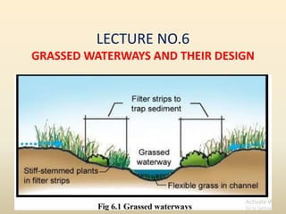
  • 2. Vegetated Waterways or Grassed Waterways • Grassed waterways are natural or manmade constructed channels covered with vegetation. • These channels are used for the safe disposal of excess runoff from the crop lands to some safe outlet, namely rivers, reservoirs, streams etc. without causing soil erosion. • Terraced and bunded crop lands, diversion channels, spillways, contour furrows, etc. from which excess runoff is to be disposed of, preferably use constructed grassed waterways for safe disposal of the runoff. • The grassed waterways outlets are constructed prior to the construction of terraces, bunds etc. because grasses take time to get established on the channel bed. • Generally, it is recommended that there should be a gap of one year so that the grasses can be established during the rainy season.
  • 3. Purpose of Grassed Waterways • Grassed waterways are used as outlets to prevent rill and gully formation. • The vegetative cover slows the water flow, minimizing channel surface erosion • When properly constructed, grassed waterways can safely transport large water flows to the down slope. • These waterways can also be used as outlets for water released from contoured and terraced systems and from diverted channels. • This best management practice can reduce sedimentation of nearby water bodies and pollutants in runoff.
  • 4. Design of Grassed Waterways • The designs of the grassed waterways are similar to the design of the irrigation channels and are designed based on their functional requirements. • Generally, these waterways are designed for carrying the maximum runoff for a 10- year recurrence interval period. • The rational formula is invariably used to determine the peak runoff rate. • Waterways can be shorter in length or sometimes, can be even very long. • For shorter lengths, the estimated flow at the waterways outlets forms the design criterion, and for longer lengths, a variable capacity waterway is designed to account for the changing drainage areas.
  • 5. Size of Waterway The size of the waterway depends upon the expected runoff. A 10 year recurrence interval is used to calculate the maximum expected runoff to the waterway. As the catchment area of the waterway increases towards the outlet, the expected runoff is calculated for different reaches of the waterway and used for design purposes. The waterway is to be given greater cross-sectional area towards the outlet as the amount of water gradually increases towards the outlet. The cross-sectional area is calculated using the following formula: where, a = cross-sectional area of the channel, Q = expected maximum runoff, and V = velocity of flow.
  • 6. Shape of Water Way • The shape of the waterway depends upon the field conditions and type of the construction equipment used. • The three common shapes adopted are trapezoidal, triangular, and parabolic shapes. • In course of time due to flow of water and sediment depositions, the waterways assume an irregular shape nearing the parabolic shape. • If the farm machinery has to cross the waterways, parabolic shape or trapezoidal shape with very flat side slopes are preferred.
  • 7. The geometric characteristics trapezoidal waterways . In the figure, d is the depth of water flow b is bottom width t is the top width of maximum water conveyance T is top width after considering free board depth, (D - d) is the free board and slope (z) is e/d.
  • 8.
  • 9. Channel Flow Velocity • The velocity of flow in a grassed waterway is dependent on the condition of the vegetation and the soil erodibility. • It is recommended to have a uniform cover of vegetation over the channel surface to ensure channel stability and smooth flow. • Even though different types of grasses have different capabilities to resist erosion; an average of 1.0 m/sec to 2.5 m/sec are the average velocities used for design purposes. • It may be noted that the average velocity of flow is higher than the actual velocity in contact with the bed of the channel. • Velocity distribution in a grassed lined channel is shown in
  • 10. Fig. 27. 3. Velocity Distribution in Open Channel (Source: Murty, 2009) Type of vegetation cover Flow velocity, (m/s) Type Magnitude Spare green cover Low velocity 1.0 - 1.15 Good quality cover Medium velocity 1.5 - 1.8 Excellent quality cover High velocity 1.8 - 2.5 Table. Recommend Velocities of Flow in a Vegetated Channel.
  • 11. Table 27.4. Permissible Velocity of Flow on Different Types of Soil. (Source: V.V.N. Murty) Type of soil Permissible velocity, (m/s) Clean water Colloidal water Very fine sand 0.45 0.75 Sandy loam 0.55 0.75 Silty loam 0.60 0.90 Alluvial silt without colloids 0.60 1.00 Dense clay 0.75 1.00 Hard clay, colloidal 1.10 1.50 Very hard clay 1.80 1.80 Fine gravel 0.75 1.50 Medium and coarse gravel 1.20 1.80 Stones 1.50 1.80
  • 12. Design of Cross-Section • Discharge Q = a x v • for finding the area required and Manning’s formula is used for cross checking the velocity. • A trial procedure is adopted. • For required cross-sectional area, the dimensions of the channel section are assumed. • Using hydraulic property of the assumed section, the average velocity of flow through the channel cross-section is calculated using the Manning’s formula as below: where, V = velocity of flow in m/s; S = energy slope in m/m; R = hydraulic mean radius of the section in m and n = Manning’s roughness coefficient. The Manning’s roughness coefficient is to be selected depending on the existing and proposed vegetation to be established in the bed of the channel.
  • 13. • Velocity is not an independent parameter. • It will depend on n which is already fixed according to vegetation, R which is a function of the channel geometry and slope S for uniform flow. • Slope S has to be adjusted. • If the existing land slope gives high velocity, alignment of the channel has to be changed to get the desired velocity.
  • 14.
  • 15. Problem Design a grassed waterway of parabolic shape to carry a flow of 2.6 m3/s down a slope of 3 percent. The waterway has a good stand of grass and a velocity of 1.75 m/s can be allowed. Assume the value of n in Manning’s formula as 0.04. Solution: Using, Q = AV for a velocity of 1.75 m/s, a cross-section of 2.6/1.75 = 1.485 m2 (~1.5 m2) is needed. • Assuming, t = 4 m, d = 60 cm.
  • 16. The velocity exceeds the permissible limit. Assuming a revised t = 6 m and d = 0.4 m
  • 17. The velocity is within the permissible limit. Q = 1.6 × 1.7 = 2.72 m3/s The carrying capacity (Q) of the waterway is more than the required. Hence, the design of waterway is satisfactory. A suitable freeboard to the depth is to be provided in the final dimensions.
  • 18. Construction of the Waterways • It is advantageous to construct the waterways at least one season before the bunding. It will give time for the grasses to get established in the waterways. • First, unnecessary vegetation like shrubs etc. are removed from the area is marked for the waterways. • The area is then ploughed if necessary and smoothened. • Establishment of the grass is done either by seeding or sodding technique. • Maintenance of the waterways is important for their proper operation. • Removal of weeds, filling of the patches with grass and proper cutting of the grass are of the common maintenance operations that should be followed for an efficient use of waterways.
  • 19. Selection of Suitable Grasses • The soil and climate conditions are the primary factors in selection of vegetations to be established for construction of grassed waterways. • • The other factors to be considered for selection of suitable grasses are duration of establishment volume and velocity of runoff ease of establishment and time required to develop a good vegetative cover. • Generally, the rhizomatous grasses are preferred for the waterway, because they get spread very quickly and provide more protection to the channel than the brush grasses. • Deep rooted legumes are rarely used for grassed waterways, because they have the tendency to loosen the soil and thus make the soil more erodible under the effect of fast flowing runoff water. • Sometimes, a light seeding of small grain is also used to develop a quick cover before the grasses are fully established in the waterway.