Earthship biotecture
•
0 likes•494 views

In the present prevailing social economical and environmental conditions, where pollution has been continuously raising we need to construct structures that contribute towards negative carbon footprint This project puts forth a method of construction where the building acts as a living breathing cell by fulfilling all the needs of its inhabitants through encounter from all the natural phenomena like sun, rain, wing, gravity, conduction, convection and many more. Hence a building becomes a breathing organism which take care of themselves and does not need fossil fuels. Such buildings are epitome of sustainable design and constructions where no part of sustainable living has been ignored.

Recommended
More Related Content
What's hot
What's hot (20)
Similar to Earthship biotecture
Similar to Earthship biotecture (20)
Recently uploaded
Recently uploaded (20)
Earthship biotecture
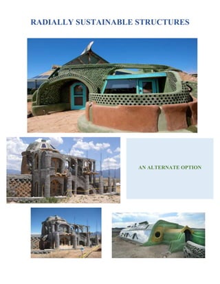
- 1. RADIALLY SUSTAINABLE STRUCTURES AN ALTERNATE OPTION
- 2. INTRODUCTION Architecture and construction today present a unique challenge in the field of sustainability. Construction projects consume large amounts of materials, producing tons of waste, and often involve weighing the preservation of buildings that have historical significance against the desire for the development of newer, more modern designs. The major element used for constructions today is concrete. A major component of concrete is cement which has its own social and economical impacts. The cement industry is one of the primary producers of carbon dioxide, a major greenhouse gas. Concrete causes damage to most fertile layer of the earth, the topsoil. Moreover, concrete is used to create hard surfaces which contribute to surface runoff that may cause to soil erosion, water pollution and flooding. Cement manufactures causes environmental impacts at all stages of the process. These include emissions of airborne pollution in the form of dust, gases, noise and vibrations while operating machinery and during blasting in quarries and damage to countryside from quarrying. The cement industry produces about 5%of global manmade CO2 emissions, of which 50%is from chemical process and 40% from burning fuel. In the present prevailing social economical and environmental conditions, where pollution has been continuously raising we need to construct structures that contribute towards negative carbon footprint This project puts forth a method of construction where the building acts as a living breathing cell by fulfilling all the needs of its inhabitants through encounter from all the natural phenomena like sun, rain, wing, gravity, conduction, convection and many more. Hence a building becomes a breathing organism which take care of themselves and does not need fossil fuels. Such buildings are epitome of sustainable design and constructions where no part of sustainable living has been ignored. We need to construct homes that do three basic things: firstly, utilize sustainable architecture and materials indigenous to the local area or recycled materials wherever possible; second, rely on natural energy sources and be independent from the grid; thirdly, are feasible for a person with no specialized construction skills to build. The whole idea of such a house in one piece is extremely successful because the easily accessible materials do not require specific skills and can be assembled by less skilled labor. Such structures are all about, power, water, sewage, food, recycled materials and the resulting insignificant economy. It is about learning to endure without being dependent on any additional systems; political, economic or utility. If nations brand their first priority providing individuals with awareness of how to provide for themselves in a sustainable survival, then their livelihood will not lay open to the ups and downs of an economy A radially sustainable structure performs towards rising fully established structures, self-sustained in terms of power, water, sewage, food, recycled materials and the resulting economy, having a
- 3. zero-carbon footprint impact on the planet. It is a building prototype that yields its own electricity and water; contains and treats Its own sewage; and cools and heats itself devoid of fuel and produces a noteworthy quantity of food. The six basic principles which are followed for such constructions are: Building with recycled materials: Waste automobile tires are used which are jam-packed with compacted earth in order to form rammed earth bricks encased in steel belted rubber. The resulting bearing wall it forms is almost imperishable. Aluminum can walls make very robust walls. These cans fashion a cement matrix which is very tough and easy to build. Bottles can create lovely colored walls that light shines through. Passive temperature control: The resources used are dense and enormous which store energy. The sun rays are absorbed by the mass thus keeping the interiors cool during the day and releasing the heat inside in order to keep the house warm during the night thus creating a building that is apposite for all climatic conditions. Greenhouse are provided in the interiors and exteriors of the house along with an underground ventilation system in order to keep the atmosphere fresh and cool. Insulation is provided in the roof and thermal mass on order to control the temperature flow. Generate own electricity: Wind turbine, micro-hydro-turbine, bio diesel, natural gas and photovoltaic cells are used for self-energy generation. Harvest own water: Even the most arid climates can provide enough water for daily use through only a rain-harvesting system. Rainwater is used as the major source of usage of water. Rainwater is filtered into wells which is further used. The water is reused for four times before finally being disposed. Sun is used for heating of water. Contained sewage treatment: The water used primarily for drinking then goes to the indoor greenhouse plans. This water is then used in the toilets from where the black water is disposed into the septic tank outside and the storm water is further used for the outdoor plants. There is no ground water pollution because of the storm water because the roots clean the water. Own food production: Tropical used are grown indoors and permaculture is practiced outdoors in order to meet the basic food requirements by the natives
- 4. CONSTRUCTION PROCESSES INVOLVED A. TYRE WALL CONSTRUCTION The basic element used for construction of the main bearing wall of the house are earth rammed tires. Automobile tires come in sizes called 13, 14, 15 and 16. These sizes relate to the radius of the tire in inches. The steps involved in the tire wall construction are: 1. The first course of tires of any tire wall must be leveled and dug into undisturbed soil free of organic surface matter such as plants, tree roots or any other biodegradable substances 2. The first course of tires must be as large in diameter or large in diameter than any other tire in the wall. No tire may appear in a wall that is larger in diameter than the tires on the ground course of that wall. The walls are really the only aspect of a tire building that is significantly unconventional. The roof and floors use conventional materials. Therefore, a thorough presentation of the standards for bearing and retaining walls made from automobile tire casings rammed with earth will be used as a guide to those whose job it is to inspect tire buildings for structural integrity, safety and quality. 1. TIRE SIZES USED IN BEARING AND RETAINING WALLS Automobile tires come in sizes called 13, 14, 15 and 16. These sizes relate to the radius of the tire in inches, #13 tires being the smallest tires used in a bearing or a retaining wall and #16 tires being the largest. These sizes will be specified in different parts of the structure as such.
- 5. 2. TIRE WALL AS FOUNDATION In that a tire wall is already wider than its required foundation, it becomes a monolith which is both wall and foundation The first course of tires of any tire wall must be leveled and dug into undisturbed soil free of organic surface matter such as plants, tree roots or other biodegradable substances. The first course of tires must be as large in diameter or larger in diameter than any other tire in the wall. No tire may appear in a wall that is larger in diameter than the tires on the ground course of that wall. Tire walls over six courses high must have a ground course of tires #15 or larger exclusively.
- 6. 3. COURSING All tire walls must use staggered running bond coursing. Joints between tires on any given course must be aligned with the central area of all tires on courses above and below. No joint between tires on any given course may align with any joint on the courses above or below. 4. HALF TIRE TECHNIQUES CONCRETE HALF TIRES Concrete half tires must use a mix of 3 parts cement-4 parts sand-5 parts gravel with engineering fibers. All tires adjacent to concrete half blocks must be porcupined with 16dnails to lock concrete to tires. In that concrete half tires are the most substantial half tiremethod, they will be specified in some situations by the architect. All two-story tire wall applications will use concrete half tires. RAMMED EARTH TIRES Rammed earth half tires are made by cutting a tire in half and leaving tabs on the sides to screw into the adjacent tire. This half tire is then pounded like a regular tire. Rammed earth half tires can be used only in tire walls five courses high or less and never at the end of a wall.
- 7. 5. BEARING WALLS All bearing walls built from earth rammed automobile tire casings must have a continuous bond beam of wood or concrete All bearing walls eight courses or higher for their entire length built from earth rammed automobile tire casings must have a continuous bond beam that connects to a continuous bond beam on adjacent nonbearing tire walls. 6. RETAINING WALLS All retaining walls built from earth rammed automobile tire casings must be stepped back or lean into the earth they are retaining. Specifications and construction drawings certified by a licensed architect or engineer must appear in the stamped construction drawings for the permitted building for all retaining walls built from earth rammed automobile tire casings. 7. FREE STANDING WALLS DEFINITION - Any wall not tied into the roof structure of a building. All free-standing walls over 2 courses high built from earth rammed automobile tire casings must have continuous arcs built into the design of the wall. These walls cannot be straight for any distance. Free standing walls built of earth rammed automobile tire casings cannot be over 5 courses high unless designed by an architect and certified specifications and construction drawings are provided for that wall.
- 8. 8. PLATES AND BOND BEAMS All tire walls that are an integral part of the roofed building shall have a continuous wood or concrete bond beam. This bond beam shall be anchored to the tire wall with 1/2" anchor bolts set in concrete every other tire or 1/2" rebar driven down through three courses of tires and bent over the top of the wood plate or set in the concrete bond beam.
- 9. 9. TWO STORY All two-story earth rammed tire structures shall be designed by a licensed architect or engineer. A continuous 9" deep x 2'-0" wide concrete bond beam must occur at each floor level. All tires on the first level must be #15 or larger. All tires on the second level must be #14 or smaller. All blocking must be concrete. All void packing on the first-floor level walls must be concrete. 10. LENGTH OF WALLS There is no limit to the length of earth rammed tire walls, since rammed earth tire walls are not made of a rigid material that is sensitive to expansion/ contraction cracks. 11. HEIGHT OF WALLS The maximum height for a straight earth rammed tire wall which is an integral part of a structure with a roof or floor load is 10 feet. At this point a wood or concrete bond beam must be installed The maximum height for a circular earth rammed tire wall which is an integral part of a structure with a roof or floor load is 12 feet. At this point a wood or concrete bond beam must be installed The maximum height for a free-standing earth rammed tire wall that is not a curved or a battered retaining wall or otherwise structurally integrated into a building is 6 feet. There is no maximum height for a battered retaining wall constructed from earth rammed tires. All battered retaining walls must be engineered by a licensed architect or engineer.
- 10. 12. LOADING OF WALLS Loading on earth rammed tire walls must be distributed loading only from joists, beams or rafters setting on a continuous wood or concrete bond beam No point or collected loading is possible on earth rammed tire walls unless special engineering is provided by a licensed engineer or architect. The limits of the evenly distributed load an earth rammed tire wall can accept are determined by the bearing capacity of the soil that the earth rammed tire wall is setting on. In cases where an earth rammed tire wall is setting on rock or a concrete foundation which is wider than the tire wall itself and more than typical roof or second story loading is desired, the bearing capacity of the tire wall will be determined by a licensed architect or engineer. 13. FILL OF WALLS Earth rammed tires walls can be filled or rammed with any type of earth, clay, sand or rock fill. All tire casings must be packed tight to 90% compaction with a 6# to 9# sledge hammer. Soft spongy tire packing is not acceptable. A cardboard larger than the size of the diameter of the tire should be places beneath each tire so that the dirt retains within the tire and does not flow out. A 1inch screw with a thread going all up the head should be pushed down on all four intersecting sides of the tire in order to hold the adjacent tires firmly in place. Each layer needs to be 1.5inch back from the previous layer so that the tire wall will lean back firmly into the berm helping in the stability of the tire wall.
- 11. Fill the dirt in three layers into the tire. Put the earth towards the wall of the tire so that it adjusts well with your hand for the first two layers. Use pick axe after the third layer to raise the tire edge and push the dirt inside Use the sludge hammer after filling in order do compact the soil so that all the voids are cleared. Pound with the sludge hammer, little bit off the center towards the corner approximately at an angle of 45` into the side wall. Use stones while tempering with the hammer so that the stones move towards the side walls and keep the diet in place and also provides resistance against the vibrations. 14. LEVELLING Each tire should be measured horizontally from front, back and center with respect to the previous tire and vertically within the tire with the help of a levelling rod. The first tire of each row should be taken as the reference tire. Vent tubes which are installed along with the second layer of the tire should also be levelled with the reference tire.
- 12. 15. EARTH CLIFFS All Earth cliffs shall be 12" minimum from an earth rammed tire wall. All earth cliffs shall be approved as a result of site and soil inspection by a licensed architect or engineer. 16. JOINTS All joints and connections in earth rammed tire walls must be designed and assembled in such a way so that no voids occur within the earth rammed tire wall. These voids must be filled with concrete or 90% compacted earth contained in a double layer of metal lath or a rubber tire casing. All joints and connections in earth rammed tire walls must employ over lapped tires and joining methods so as not to result in stacked joints occurring over each other. 17. FINISHING All the tires are porcupined with nails so that the concrete has something to stick to while finishing. Concrete, adobe, mud fuska and plasters can be used for plastering and finishing the tires. Finishing should be done carefully so that all the joints are covered completely. A thermal wrap is to be provided behind the tire wall
- 13. The best things about building with such tires is: Tires being waste materials are easily available in approximately no cost. Such waste materials reduce the energy consumptions required for manufacturing other conventional building materials. The waste which is being utilized is helping in efficient reduction of waste. Tires and cans have a really good resale value and can be reused again and again if degraded but if the conventional building materials like concrete n bricks if degraded due to some reason will not only effect the life of the structure but also cannot be used potentially again. The soil which is used to fill the tires does not require extensive tests and analysis. The dry soil which is available on the site can be simply used to fill the tires and compact it with simple equipments like a temper. Such constructions are slightly time consuming but have high workability and do not require especially skilled labor. Earthquakes are an issue in many parts of the world. Any method of building must relate to this potential threat. Since earthquakes involve a horizontal movement or shaking of the structure, this suggests a material with resilience or capacity to move with this shaking. Brittle materials like concrete, break, crack and fracture. The ideal structural material for dealing with this kind of situation would have a 'rubbery' or resilient quality to it. This kind of material would allow movement without failure. A. THERMAL WRAP The materials that surround the spaces of as such homes are dense and massive in order to store the temperatures required to provide a habitable environment for humans and plants.
- 14. Such structures rely on a balance between the solar heat gain and the ability of the tire walls and subsoil to transport and store heat. They are designed to use the properties of thermal mass and with the intent that the exterior earth rammed tire walls provide thermal mass that will soak up heat during the day and radiate during the night, keeping the interior climate relatively comfortable all day. In addition to the exterior tire wall, some homes can sink into the earth to take the advantage of earth-sheltering to reduce temperature fluctuations. The thermal wrap is provided in the form of a 4inch thick fine insulation which is placed at a distance of about 4feet from the tire wall. A 6feet wide plastic sheet is placed on the ground between the thermal wrap and tire wall which acts as a vapor barrier to keep the moisture coming out of the earth into the wrap barrier. This area is finally filled with the dirt available on site in order to create a solid thermal mass which finally provides protection from the temperature fluctuations prevailing in the exterior of the wrap and the interior of the home thus maintaining an approximately constant and soothing temperature throughout. B. COOLING TUBES The main purpose for providing cooling tubes which extend from the interior of the house under the berm, cools the air by the time it gets to the comfort zone. As the hot air rises, the system creates a steady airflow of cooler air coming in and warmer air blowing out through a smaller vented window in the greenhouse. These cooling tubes are 40feet long tubes of 10inch diameter made out of galvanized coper which run from the interior of the house through the thermal mass directly to the other end. A channeled space is firstly excavated to that this pipe can be laid along the course of tires. The tube is usually levelled with the second course of the tires. The excavated area is finally filled with the thermal mass with is usually the dirt available on site such that this tube is well covered with thermal mass. This mass helps the air to cool as it flows through the tube into the comfort zone
- 15. C. ROOF Above the final layer of the wall a bond beam is made. A bond beam is laid over the final layer of tires by adjusting cans with cement into continuous layers filling concrete in between the layers and reinforcing it. The bond beam is bolted in top and a layer of 2/6 trex is places over it. Trex is a plastic like material which takes the place of wood and does not get rot over time. This is usually used over the bond bean since wood can rot due the moisture present in the concrete. EPDM rubber is places over the trex where the wooden beams are to be places till the end of the wooden beams so that no moisture enters the wooden beams in order to detoriate it. The EPDM rubber is sandwiches between the two trex plates which makes a really tight pressure seal. Once the wooden beams are all set, they are levelled at one level.
- 16. Over the bond beam plating the wooden beams are places over shims which are usually trex pieces. It is further drilled through the wooden beams into the shims till the plating and into the bond beam. A rebar is sent down through the drilled hole ad is hammered from top tapering it, so that it sets tightly. Once that wooden beams are fixed and screwed with shims, the ends of the wooden beams are all cut into one level so that they flush with one another. DECKING: After the bond beans are placed a 1/8inch decking is places over it in order to receive the final roofing layers. The decking is finished on all four sides by nailing. Now, a waterproof asphalt seal is places on top of the deck which is nailed with a staple gun. The mail purpose of using asphalt is that it is a water resistant material and does not allow any water to penetrate into the decking into the bond beams which can ultimately destroy the whole roof.
- 17. Over this waterproofing layer, an 8inch polyiso insulation is provided which is again provided for greater insulation properties. The final covering is given by 1/4inch purlins which are screwed with iso screws through into the bond beams. The final covering has channels made in its design so the rainwater can easily flow through the roof into the cisterns installed behind the wall. PERFORMANCES OF SYSTEMS INSTALLED IN THE HOUSE A. WATER The water from clouds is captured on the roof and channeled through gravel filters and silt captures so that when it reaches the cistern it is clean. A total of four cisterns having a capacity of 1700gal each made out of plastic are installed behind the tire wall into the thermal wrap. The water from cisterns is then gravity fed into a water organizing module. The pump then filters the water into a pressure tank for consumption and household usage.
- 18. B. SEWAGE Every time we wash something or flush the toilet, we create waste water. Waste water from sinks, showers, baths, kitchen and washing machines is called grey water. Usually gray water will contain chemicals like soaps and detergents and easily degradable organic materials like fat and oils. These detergents contain nitrogen and phosphorous which are utilized for plant growth. Consequently, this grey water is channeled through filter or digester in order to absorb the greasing particle and then sent to in indoor botanical call.
- 19. A botanical cell in a buildup soil ecosystem which contains various soil layers. The first layer is composed of gravel which allows water to flow and provides good aeration or oxygenation preventing nasty smalls. At the top of the botanical cell, plants absorb water by the process of transpiration, enabling water to be absorbed by the roots. When the nearby root soil dries out, the water at the bottom slowly flows towards the dry soil nearing the plant. This flow of water allows the phosphates and household chemicals to be completely absorbed and thus filtered. The peat moss provides additional filtering, efficiently eliminating the heavy metals if any. At the end of the botanical cell, there is a grey water organizing module which pumps the treated water to the toilets. Once the toilets are flushed, wahet now contains fetal substances and lots of organic material. This is called the black water. This water then goes to the septic tank where the liquids are separated from the solids. This treated water is then channeled for exterior landscaping purposes. In short, earthship makes vary efficient use of water by making it use four times: 1. By using it for washing and bathing purposes, 2. Then by using it to water in indoor plants, 3. Then to flush the toilet, and 4. Finally, by using it to water the outdoor plants.
- 20. A. FOOD PRODUCTION In order to grow, survive and reproduce, plants need water, sunlight carbon dioxide, oxygen and nutrients like, phosphorous and nitrogen. All of these can be easily found inside such a house allowing many plant options to grow round the year in the botanical cell. In short, such structures can grow food year round by providing sunlight round the year, protection of plants from extreme weather conditions, an automatic watering system, a good soil composition and nutrients from grey water like nitrogen and phosphorous. B. THERMAL SOLAR HEATING AND COOLING The outer few feet of the earth heats up and cools off in response to surface weather. However, deeper in the earth, about four feet and beyond, the temperature is more constant (around 58 degrees). Here, the earth can be used to both cool and stabilize temperature if the home is appropriately designed. Such structures are thermal mass homes first, passive solar homes second. Therefore, their layout and designs can be completely customized to look like any conventional home, and still be sustainable. The "generic" designs are what works the best, both in terms of economics and energy efficiency. Because of the way these structures interact with the sun and the earth, little to no fossil fuels are required to maintain a comfortable, stable temperature in any climate.
- 21. A. WARMTH If you want heat, you admit the sun. The sun heats the mass, the mass stores the heat and the insulation won't let it escape. The more mass, the more storage capacity. When there is no sun, the heat stored in the mass radiates into the space, for heat travels to the cooler direction. B. COOLNESS If you want coolness, you admit the cooler earth temperature and block the sun. The cool mass of the earth connects with the mass of the shelter, is absorbed into the shelter mass and leaks into the living space. This is like hooking a big battery (the earth) up to a smaller battery (the shelter). The thermal mass of both the earth and shelter is a storage battery for temperature. C. INSULATION & THERMAL MASS In recent years’ humans have recognized the fact that insulation can help keep temperature in a shelter. Insulation, however, neither collects nor stores temperature. It simply blocks the passage of temperature from inside to out and vice versa. Good insulation has millions of tiny air spaces. The presence of air spaces tends to slow up the movement of temperature by causing it to pass from air space to air space as opposed to moving easily through unobstructed dense mass. Dense mass both collects and stores temperature like a jar holds marbles. Examples of dense mass are stone, water, compacted earth, or concrete. There is a major difference between mass and insulation and this difference is not very clearly understood. Dense means no voids or air spaces. The denser the mass the more temperature it holds. This density actually acts as a conduit for temperature.
- 22. D. SOLAR ELECTRICISTY Photovoltaic cells are made using semiconductors which are mainly silicon. Pdosphorous atoms bonded with silicon, leaves one electron not bonded, resulting in negative silicon because of the prevailing electron. On the other side of the solar cell boron is added. Atoms are also bonded but in this case one free opening is available for an electron, making positive silicon. When these two sides are put together, a mad rush of electrons flow to the positive side. Eventually equilibrium is reached and an electric field is created. This conducts electric current in only one direction. When light in the form of photons hit the solar cell, it excides the electrons and the field sends the electrons to the negative side. The metal contacts on the top and bottom draws current off streaming towards another cell and so forth creating a cell or module. When packed into a frame, a solar panel is created. This can provide electricity clean and quietly for the next thirty years Fast moving wind is a really good source of generating green energy which can be utilized in order to light the house and also for many other purposes. Such natural methods not only help the structure survive but also maintaining a green and healthy atmosphere around and help reducing the public energy needs to a great extent. Apart from providing energy to the house, such methods can also help provide energy around the house just like for street lights. As air partials collide against an object, each of them pushes with an amount of energy. The wind blades capture wind energy and start moving. They spin a shaft that leads the rotor to a generator where a magnet spins. The conductor which surrounds these magnets indices a current which drives out through the power lines.
- 23. This is all about transferring green energy from one medium to another. The power generated by all sources go to the power organizing module. This distributes energy to the battery. When fully charged, it stops charging and sends the current for household usage. It also prevents overloading of batteries, making them last longer. ENIRONMENTAL IMPACTS Such radially sustainable structures generate beneficial contributions to the environment issues like: 1. ENERGY CONSUMPTION Fossil fuels supply about 90% of the world’s commercial energy. This has to stop. Such structures reduce energy need to a minimum by:
- 24. Not needing central heating and air conditioning. By generating their own green energy, they contribute to minimize global warming. 2. SEWAGE The sewage systems in most of the places around the world are inefficient. Normally we don’t separate gray water from black water and in most places, there ant any water treatment plants, so the potential grey water which can be further reused within the house is mixed along the black water and is directly dispatched into the rivers or lakes etc. hence polluting them. Such structures use water in such an efficient manner that there is no actual discharge of water from the house and so all the water which is being consumed within the house for various purposes stays inside the house. 3. FOOD CONSUMPTION Global agriculture uses 60% of the total fresh water in the world. Food production today has to be technified in order to meet the large demand, resulting in burning fossil fuels, chemicals and pesticides therefore, emitting greenhouse gases, polluting soil, water and product itself. Moreover, food is regulated by the economical market making it vulnerable to shifts in market and availability. Such structures produce food year round reducing expenses in family economy, health risks associated because of pesticides and contaminants where the food is grown, carbon dioxide emissions by fuel consumption, for example, transportation of food from long distances. 4. WASTE Everything we consume is a potential waste because nothing is used forever. Some materials no longer used don’t degrade, but occupy space and contaminate the environment in several other ways, for example, tires. Such materials when used for construction help to reduce pollution and also is an extremely efficient way of utilizing a potential waste.
- 25. PROTOTYPE STUDY Following are the details of a small scaled prototype which I attempted to make at my institute by using waste cycle tires. A final prototype of a radially sustainable structure was created by our group. The site area was taken to be approximately 95 sq. Feet. the building blocks were taken to be waste cycle tires. Each waste tire was cut into four parts and then stitched up to make them into proper tires of a smaller dimension. Each resulting tire turned up to be of …mm diameter. The base for the prototype was made out of bricks so that the model comes up to the eye level. A thick earth layer was laid up and the foundation for the prototype was set up. The best thing about such structures is that even in the real-life constructions, intensive soil testing are not requires and one can just simplystart the construction work by just laying a simple 2-3-layer tire foundation. A cardboard was placed within each tire and the earth was filled into it in layers and tempered perfectly so that the soil gets well compacted. Eight tires were places at the back of the house and six at each side. The front of the house was left open were a wooden frame supporting the roof was placed at the end. Tires were further placed alternatively over each other so that no center of the tire will coincide with another. A wooden plank representing the poly-iso thermal insulation sheet was placed approximately 10inch behind the tire wall. The tire wall was externally binded with the help of the on-site available soil, so that a perfect thermal insulation wrap is created and a constant temperature is maintained throughout. Twelve such tire layers were placed in order to complete the wall and a representative can wall was placed over it in order to receive and support the roof frame. A partition wall was created inside the structure. Such partitions in a real-time structure are actually utilized to receive and further circulate all the water from the cistern placed in the backfill into the structure. All the plumbing works which are carried out of 2inch PVC piper are situated within this partition and the transmit water throughout the structure to kitchen and bathroom and in any other place required except for the WC. All the utilized water also known as grey water is again collected with the help of these 2inch PVC pipes and then send to the indoor botanical cell which is situate in the front façade. The potassium and nitrates which are present in the gray water are useful for the plant growth and hence are absorbed by the roots of the plants growing over this botanical cell. The water from this botanical sell the further sent to the WC with the help of a 3inch PVC pipe located the one end of the botanical cell. The water which becomes black after flushing is then sent to a septic tank which is situated outside the house where the solids and liquids are separated and all the left-over water is then used for water in all the outdoor plants. All the water is completely utilized in this manner and thus no water is waster. All the water which comes into the property stays within the property itself. Practicing of permaculture both inside and outside the house makes the environment more serene and lively and also remarkably helps in pollution control. CHALLENGES FACED The main issues faced are listed as follows: Enough space for construction was not available due to which we had to take up a smaller size for the prototype and hence we thought of cycle tires. The soil had to be transported to the site which was a difficult task due to lack of labor.
- 26. SECTIONAL MODEL OF THE PROTOTYPE
- 27. CONCLUSION Today we are simply adapting our needs to the already existing activities of the planet. Why pipe water long distances from a centralized community water system, or from an expensive well that needs significant electrical power, depletes aquifers and lowers the water table, when water fall from the sky? Why have a corporate or political "middle man" between us and our energy needs? our vessel (home) must be designed to sail with the forces that exist beyond human control and exploitation. An understanding of mechanical systems for most humans is limited to what is within reach of their fingertips. It is understood that when you flip a switch on the wall, a light comes on. when you turn on the faucet, hot water comes out. When you pull the handle on the toilet, it flushes. Little though is given to where the electricity comes from or what kind of nuclear waste was produced to generate it. How many of us even know where the power plant is that supplies our power? Few people ever wonder which water table is depleted to bring them water and what chemicals have been added to it. Where does the sewage go after it is flushed and which rivers and lakes are polluted by it? Humans need comfortable temperatures, light, electricity, hot water, food, sewage treatment, etc. These necessities are all available within the framework of a certain "rhythm" in such structures. The more we are able to align our priorities and needs with the prevailing rhythms of the planet, the easier and less expensive (both in terms of economics and ecology) they will be to obtain. If our lifestyles can conform more to the patterns of the planet than to our socioeconomic system, we can reduce the stress on both ourselves and the planet. This is easier said than done due to the "reality" and the "gravity" of mortgage payments, utility bills and the generally high cost of eating and living. Most of us have no choice. We have to be places at certain times looking certain ways in order to make the money needed to make those payments. However, such radially sustainable structures have the ability to produce food round the year resulting in a great saving in the amount spend in purchasing natural or packed, processed food and also saves from the negative nutritional impacts generated by them in the present environmental and other conditions. The condition of our planet tells us we must now begin to take responsibility for what happens beyond the reach of our fingertips. We must begin to reconsider the source of these utilities, our access to them, and how we dispose of the waste produced. The mechanical systems of the such radially sustainable structures confront these issues directly. We call this direct living. Source, access and destination are all contained within the home, within the reach of our fingertips. There is no mystery involved in the electricity being received by generation on its own. There is no unknown source of water. There is no magical black hole that sucks up all our sewage. Instead, we work in harmony with the earth to deal with these issues - taking what it has to give us directly and giving back what it wants to receive. With this harmony ringing in our minds we evolve the sustainable Systems.
- 28. In conclusion, such radially sustainable structures can help our economy and can be beneficial for local, regional and global problems.