1. T echnical F eaTure
G/T for a SaTelliTe-
TerreSTrial HandSeT
wiTH inTernal and
exTernal anTennaS
In this paper, the figures of merit for a satellite-terrestrial handset with internal
and external antennas are extracted, based on the antenna measurements with
the handset mechanics in free space. The gain statistics are derived from the
measured antenna patterns. The antenna noise temperature is calculated from
the sky brightness, the antenna efficiency and loss, and a few critical conclusions
are obtained.
T
he figure of merit (G/T) for a satellite- the peak gain is taken at a 20° elevation, the
terrestrial handset is a critical parameter G/T is underestimated, while if the peak gain
for the link budget calculations, where G is taken at a 90° elevation, then the G/T is over
is antenna gain, which varies with elevation and estimated. For an internal PIFA, the gain pat-
azimuth angles, and T is the system noise tem- tern and noise temperature are affected more
perature, which is the sum of the handset re- by the other components around the antenna.
ceiver and its antenna noise temperatures. For In the following section, it can be found that
the Terrestar GENUS smart phone, an internal the PIFA radiation pattern is more random in
Planar Inverse F Antenna (PIFA) is used1 for the preferred elevations, that is 20° to 90° and
satellite communication in the primary service in the whole azimuth plane. In the GMR-1 3G
area. In addition, a novel external helix-octafilar Specification,2 no terminals with an internal an-
antenna has also been designed as the accessory tenna are available and it is hard to determine
to support secondary service areas. the antenna gain and noise temperature to de-
In the GMR-1 3G Specification,2 the figures rive the corresponding G/T. In this article, the
of merit for several types of satellite receivers work is based on free space antenna measure-
are available with only external antennas. The ments with approximately 3° angular steps for
G/T ratio of the various packet data terminals both the internal PIFA and the external helix-
in the direction of the peak antenna gain under octafilar antenna. The gain G in G/T is proposed
clear sky conditions, with the antenna fully de- to be a statistical value derived in the preferred
ployed and with no conducting objects in the elevations from 20° to 90°. The antenna noise
vicinity of the unit, at 20°C, will exceed the temperature is derived by considering the an-
tabulated G/T values at elevations over 20°. tenna efficiency, loss and the brightness seen by
For a similar terminal as the GENUSTM smart the antenna. Then some proposals are offered,
phone with external antenna (terminal E), the regarding the derivation of the G/T.
given G/T is −30 dB/K in which the given an-
tenna gain is −1 dB, the antenna noise temper- AntennA GAin MeAsureMents And
ature is 150 K, and the receiver noise figure is 5 GAin stAtistics
dB. The G/T definition2 has caused ambiguity In the GENUS smart phone, the internal
when deriving it using the actual antenna mea- PIFA is located in the upper right corner seen
surements with the handset mechanics, espe-
cially about how to define the antenna gain G. �X.�Zhao,�T.�Haarakangas,��
It appears that G is a peak antenna gain, but it J.�Katajisto,�M.�Niemi,�P.�Myllylä,�
is unclear which elevation to use, because the J.�Inget�and�J.�Alasalmi
peak gain varies with the pointing elevation. If Elektrobit (EB), Oulu, Finland
78 MICROWAVE JOURNAL AUGUST 2011
2. T echnical F eaTure
larization (LHCP). The first row shows the statistical gain is also extracted and
the PIFA patterns, while the second shown in Table 2. From Table 1, it can
row is for the helix-octafilar prototypes. be seen that the gain repeatability is
For both the internal and external an- extremely good for the three PIFA and
tennas, the design objective is to have octafilar prototypes, respectively. The
a good and stable gain pattern in the helix-octafilar has better gain statistics
preferred elevations and also in the than the PIFA, especially in a small
azimuth plane. Obviously, the helix- Cumulative Distribution Function
octafilar (being a larger antenna) has (CDF), that is approximately 8.6 and
better gains in 20° to 90° elevations. 4.7 dB more gain at 1 and 10 percent
Figure 3 shows the gain pattern cuts CDF, respectively.
for Antenna #1 in specific elevations
for the PIFA and the helix-octafilar. the systeM noise
From the figures, it can be seen that teMperAture And G/t
the PIFA gain varies considerably, es- The G/T (dB/K) can be calculated
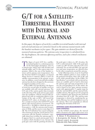
s Fig. 1 Measurement coordinate system. pecially at low elevations. The gain for from G -10 log (T), where G is the an-
from the back cover. There is an RF the helix-octafilar is more stable for a tenna gain and T is the noise tempera-
port available in the upper right cor- fixed elevation, but the instant gains ture of the system, which is the sum
ner as well for using an external anten- show a big difference at the low and of the antenna and the handset noise
na. Only one of the antenna ports is high elevations. Therefore, from the temperatures. The antenna noise tem-
available at a time. A user must select random PIFA gains, a statistical gain is perature is derived by considering the
the preferred antenna from the hand- extracted and listed in Table 1. Then, a antenna efficiency, loss and the bright-
set operating system menus. The gain reasonable gain is chosen for use in its ness seen by the antenna. The sky
measurements are done using the co- G/T calculation. For the helix-octafilar, brightness and how it is seen by the
ordinates shown in Figure 1.
PIFA#1 PIFA#2 PIFA#3
Figure 2 shows the gain patterns
(θ = 90°− elevation°) in free space for
the forward link (from the satellite to 50 50
50
handset) with the left hand circular po-
(°)
(°)
(°)
100 100 100
0
150 150 150 –5
–10
0 200 0 200 200
(°) (°) (°) –15
HELIX-OCTAFILAR#1 HELIX-OCTAFILAR#2 HELIX-OCTAFILAR#3
–20
WEST·BOND INC. WEST·BOND INC.
–25
50 50 50
–30
BOND
(°)
(°)
(°)
100 100 100
WIRE BOND
150 150 150
0 200 0 200 0 200
(°) (°) (°)
s Fig. 2Gain patterns for the PIFA and helix-octafilar prototypes, forward link (LHCP at
2190 MHz).
tABLe i
piFA GAin stAtistics And G/ts
Gain Statistics (LHCP)(elev. 2090 degree)
PIFA
Min. CDF 1% CDF 10% Mean Median CDF 90% Max.
Ant#1 -14.2 -13.3 -7.2 -3.1 -2.1 -0.6 0.1
Ant#2 -14.7 -13.6 -7.7 -3.3 -2.2 -0.7 0.0
WEST·BOND INC. WEST·BOND INC.
Ant#3 -15.0 -13.8 -7.7 -3.3 -2.2 -0.6 0.2
Mininum gain -15.0 -13.8 -7.7 -3.3 -2.2 -0.7 0.0
www.westbond.com G/T (dB/K) -50.0 -42.8 -36.7 -32.3 -31.2 -29.7 -29.0
80 MICROWAVE JOURNAL AUGUST 2011
3. T echnical F eaTure
PIFA: ELEV. 20°
30° ∫ Gmeas (φ, θ)Tsky (φ, θ)∂Ω
40° 4π
50°
TB = (1)
60°
90°
∫ G meas (φ, θ)∂Ω
4π
HELIX-OCTAFILAR 20°
30°
40° Where Gmeas is the measured to-
50° tal gain pattern. Finally, the antenna
60°
90°
noise temperature can be calculated
from:
( )
2
TA = T0 ηrefl − ηtot + TB ηtot (2)
0
–2 Where T0 is the physical tempera-
GAIN (dB) –4 ture, which is 290 K. ηtot is the mea-
–6 sured antenna total radiation efficiency
–8
(total power). ηrefl = 1−|Γ|2 is the reflec-
tion efficiency, where Γ is the reflection
–10
coefficient, which is calculated by the
–12
measured return loss. The total radia-
–14 tion efficiencies4 of the antenna proto-
0 50 100 150 200 250 300 350 types are calculated and listed in Table
(°) 3, from which very good repeatability of
s Fig. 3 Gain patterns for the PIFA #1 and the efficiencies for the PIFA and helix-
the helix-octafilar #1 at specific elevations, octafilar prototypes can be observed.
forward link (LHCP at 2190 MHz). The total efficiencies for the internal
antenna are based on the following as- and external antennas are very close.
sumptions and equations. Figures 4 and 5 show the measured
• Calculation of the sky brightness return loss of the three PIFA and helix-
(Tsky) by considering: octafilar prototypes, respectively, used
• Temperature of atmosphere emis- in the calculation of ηrefl. The frequen-
sion: 270 K cy ranges are 2000 to 2020 MHz and
• Cosmic background noise: 3 K 2180 to 2200 MHz for the return link
• Atmosphere attenuation: and forward link, respectively. From
– Oxygen absorption: 0.007 dB/ Figures 4 and 5, the return losses are
km very low in the frequency range of the
at 2 GHz forward link. The return loss at the mid-
– Height of atmosphere: 10 km. dle frequency 2190 MHz is selected in
– Vapor and cloud attenuation the calculations. The final antenna noise
are not significant. temperatures for the prototypes are
• Sky brightness seen by the antenna:3 extracted and shown in Table 3. In the
tABLe ii
heLiX-octAFiLAr GAin stAtistics And G/ts
Helix- Gain Statistics (LHCP)(elev. 2090 degree)
octafilar Min. CDF 1% CDF 10% Mean Median CDF 90% Max.
Ant#1 -5.7 -4.8 -3.0 -0.3 0.3 1.4 2.0
Ant#2 -6.1 -5.2 -2.9 -0.4 0.2 1.2 1.7
Ant#3 -6.2 -5.2 -2.9 -0.4 0.3 1.0 1.4
Mininum gain -6.2 -5.2 -3.0 -0.4 0.2 1.0 1.4
G/T (dB/K) -35.4 -34.4 -32.1 -29.6 -29.0 -28.2 -27.8
tABLe iii
AntennA eFFiciency And noise teMperAture
PIFA Helix-octafilar
Total Efficiency Ant. Noise Temp. Total Efficiency Ant. Noise
(K) Temp. (K)
Ant#1 0.575 166.60 0.569 201.40
Ant#2 0.581 167.10 0.577 200.70
Ant#3 0.590 165.50 0.562 202.70
max: 167.1 max: 202.7
82 MICROWAVE JOURNAL AUGUST 2011
4. Products to Solutions T echnical F eaTure
RF Microwave Switches
PIFA #1 PIFA #2 PIFA #3 concLusion
0 The method and steps for extract-
–5.0 ing the G/Ts of a satellite handset,
S11 (dB)
–10.0
–15.0
with both internal and external anten-
–20.0 nas, are introduced in this article. The
–25.0
1900 2000 2100 2200 2300
receiver G/Ts, with both an internal
FREQUENCY (MHz) and external antennas, were analyzed
statistically, while the G/T of the re-
s Fig. 4 Measured return loss for the PIFA
ceiver with the external antenna was
prototypes.
compared with the result for a similar
The Ducommun RF Product Group HELIX-OCTAFILAR #1 type of terminal,2 where the -30 dB/K
has over 40 years of experience HELIX-OCTAFILAR #2 G/T is recommended but with vague
HELIX-OCTAFILAR #3
designing and manufacturing RF definition about how to get this value.
0
Mircowave Coaxial Switches and
Mir S11 (dB)
–5.0
In the case of the satellite smart phone
Switch Matrices. Our facility provides –10.0 with the external antennas, the average
the latest technical advances further –15.0 G/T is −29.6 dB/K, which is very close
–20.0
expanding our ability to address the –25.0 to what is suggested.2 For the handset
most challenging and complex 1900 2000 2100 2200 2300 with internal PIFAs, the average G/T is
Our system engineers take these compo-
requirements. FREQUENCY (MHz)
nents to develop integrated soluations to −32.3 dB/K, which is a reasonable val-
meet a variety ofHigh Power RF avonics,
applications for
s Fig. 5 Measured return loss for the helix- ue compared to the case with the exter-
octafilar prototypes. nal antennas. Therefore, the average
defense, telcommunications and satellite
Transfer Switch (T5)
communications requirements. following calculations, the worst 167.1 G/Ts in the preferred elevations can
*DC to 5 GHz
K and 202.7 K antenna noise tempera- give the better estimations. However, it
*SC Connectors is good to show the other G/Ts at differ-
*Peak Power: 50 KW tures are taken for the PIFA and the
*Ope
*Operating Life :1,000,000 helix-octafilar, respectively. The handset ent CDF points to meet with different
cycles
receiver noise temperature is 627.06 system reliabilities. Note that a linear
*Operating Temperature: gain should be taken into account in
-25C to +85C ambient K using a 5 dB noise figure. The sys-
tem noise temperatures are therefore the sky brightness calculations, due to
794.16 K and 829.76 K, respectively, for random noise. The suggested antenna
Long Life SPDT
the handset with the PIFA and the helix. noise only has the average sense in the
Switch (2EL/2ELE) whole 3D space.
In Table 1, the minimum gain G at each
*DC to 18 GHz column is taken and the final statistical
*SMA Connectors AcKnoWLedGMents
*Operating Life : 5 million cycles G/Ts are derived and listed in the last
row of the tables for the internal and The authors would like to thank
*Ope
*Operating Temperature:
Failsafe: -55C to +65C ambient external antennas. The system G/T de- their colleagues from EB, Terrestar
Latching -25C to +65C ambient
pends strongly on the antenna gain. The Networks (TSN), Hughes Network
receiver NF is slightly better than 5 dB, Systems (HNS) and RKF Engineer-
based on the measurements conducted ing for helpful discussions, especially
40 GHz Transfer Taavi Hirvonen at EB, Joe Martinet
Switch (TK4) on the handset; here a 5 dB NF is taken
as proposed.2 From Figures 2 and 3 and and Carl Ott at TSN, Michael Parr and
*DC to 40 GHz Table 1, it is seen that the antenna gains Juerg Widmer at HNS, Jeffrey Freed-
*Operating Life: 1,000,000 cycles
vary with the elevations and the azimuth man and Ted Kaplan at RKF. Special
*Operating Temperature: -35C thanks go to Joakim Granholm, Mari
to +85C angles for both the PIFA and the helix-
*Available w/ failsafe, latching octafilar. For the helix-octafilar, the av- Kähkönen and Ari Immonen at EB
self cut-off or pulse latching
erage G/T (-29.6 dB/K) might be more for their positive support of this work.
functions
meaningful, in which the mean antenna The views expressed herein are the
gain is -0.4 dB and the antenna noise authors’ and may not reflect the view
Miniature Multi Position of EB, TSN and RKF.
Switch (6SM/6SME) temperature is 202.7 K.
The G/T is proposed to be ana-
references
*DC to 26.5 GHz lyzed statistically as shown in Table 1. 1. X. Zhao, “Internal PIFA Performance Evalu-
*SMA Connectors
*RF Impedance: 50 ohms nominal
It is good to say, for instance, what are ations for a Satellite-Terrestrial Handset,” Mi-
*Si Length 3 inch by Width 1.125 inch
*Size: the minimum, average, and maximum crowave Journal, Vol. 53, No. 8, August 2010,
pp. 84-92.
*Operating Temperature: -55C to +65C G/Ts, what is the G/T for a specific CDF 2. “Radio Transmission and Reception,” GMR-
ambient
point according to the system reliabil- 1 3G 45.005, ETSI TS 101 376-5-5, v3.1.1
ity requirement. However, in practice, (2009-07).
3. J. Tervonen, “Radiowave Propagation in Sat-
one can always ask what is the G/T for ellite Communications,” Helsinki University
the handset, and then the average G/T of Technology, 2004.
might be a good value. It should be 4. “Test Plan for Mobile Station Over the Air Per-
Contact our Microwave engineers to discuss speciic requirements formance: Method of Measurements for Radi-
noted that the G/Ts listed in Table 1 are
www.Ducommun.com ated RF Power and Receiver Performance,”
Tel: 310.513.7200 Email: rfsales@ducommun.com taken directly from the gain measure- CTIA Certification, Rev. 2.1, April 2005.
ments of the three antenna prototypes.
84 MICROWAVE JOURNAL AUGUST 2011