
Recommended
More Related Content
Similar to Es exp -3 (1).pdf
Similar to Es exp -3 (1).pdf (20)
Recently uploaded
Recently uploaded (20)
Es exp -3 (1).pdf
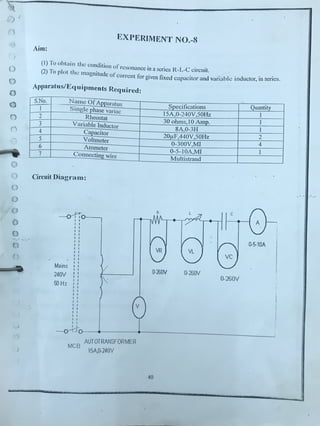
- 1. 1 l~XPEIUMENT N0.-8 • 1 Aim: ,. ) () 0 0 0 0 () .... I ' (j .._) () () f-!) 0 0 ··.· .. . () F (I) To obtain the condition orresonance in a series R-L-C circuit. (2) To plot th~ magnitude orcurrent for given fixed cupacitor and variabk inductor, in series. Apparatus/Ec1 uipanents Required: S.No. Name Of Apparatus Specifications Quantity I Single phase variac 15A 0-240V,50Hz 1 ' I 2 Rheostat 30 ohms, I0 Amp. 3 Variable Inductor 8A,0-3H 1 4 Capacitor 20µF,440V,50Hz 2 5 Voltmeter 0-300V,MI 4 6 Ammeter 0-5-I0A,MI I 7 Connecting wire Multistrand Circuit Diagram: C ~ I I 0-5-10A VR VL vc Mains 0-260V 0-260V 240V 0-260V 50 Hz ~o - +-- --+--- - - - - - - - - - MCB AUTOTRANSFORMER 15A,0-240V 40
- 2. I ~ h () 'l'ht•ofY: ,,,1 .. •ril':, l{l ,t' circuit, then: h1.:co1 11 cs ., 1 ·1 .,., 1 l, • 1 · • IN~I • 1 · l 1 • • 111· lliL· Ill ;I " , ' • u ... , l ll / 1101111 ~1't IC Jill lJCIIW rcac :11 ll ) ind1 1 c1 111 hl'l:onics equal 111 value lo the c;q1 ;1 ciIivc rcact:mcc ol' the capacitor. I 11 01 lier () words. ~ I... '.: Xe. The poinl ut which this occurs is calk<l the Resonant Frc,1ucncy point. ( /, ) ol' 0 thL: cirruil. illH.I as we arc analysing a series RI .C circuit this resonance frequency prodm:cs a 0 Srrics lkson:incc. 0 ·Sl'rie's Ne.,·o 11 w 7 cecircuits arc one of the most i111portant circuits used electrical and electronic O circuits. Thcy can he found in various fom,s such :1 s in AC mains filters. noise tilters nnd also in (; radio and television tuning circuits producing a Vl:ry selective tuning circuit for the receiving or () the dirkrcnt frequency channels. Consider the simple series RLC circuit below. Series RLC Circuit --~~ Ci R L C 0 0 ( 0 V mL0 .. 0 0 0 As we know··.··· .· 0 0 • lnductivereactance : = 21t/L c,)l C 1 1 • Capacitive reactan ce : . Xe= 2 nf C - c,)C • When x >x the circuit is Inductive L C • When X >x the circuit is Capacitive C L Total circuit reac tan ce = XT =XL- X or X,~- • Total circuit impedance = Z=✓R X~ - R 1- jX . '
- 3. f Ihl'~vcrAs Iii!.! frequency approaches 1.1.:ro or DC. the inductors rcactancc would d<;cr~asc to 1 .~ro. causing.·thc opposite dkct ;1cting like i.l sho,1 circuit. This ml!ans then that inductive n.:actancc is-"Proportional'· lo fr1.:quency and is small at low frequencies and high at higher rn:qucnc1cs. Series Resonance Frequency Capacitive Xrrn Xe> XL Inductive 0L> Xs (/) E .c 0 C Q) u C co u co (I) a: XL -Xe - 0 ► Inductive and Capacitive Reactances are equal he 1 xL"' x~ I I (fr) Series Resonance Fre(1Jency, f where: fr is in llcrlz, Lis in lknrics and C is in Farads. Electrical resonance occurs in an AC circuit when the two rcnctnnccs which nn; opposit~ and equal cancel each othci' out as Xi. Xe and th(.; point on the graph at which this hnppcns is were the two rcactancc curve:-. cross each othi;r. In a series n:sonant circuit. th0 n;~onnnt frequency,f1pnint can be cnkulatcd as follows. 42
- 4. i ~ I I I I ·, I I I I I I I xi Xe .. • 211:/L 1 211:JC ,., 1 1 1- --- 2nl / 2nC --, - ) . 41( LC f ~4-i'c 1 (H . 2n JLC z) or I- = - 1 - (rads)' - ✓ LC r , We can sec then that at rcs6nanc'c, thf two reactanccs cancel each other out thereby making a series LC combination act as a short circuit with the only opposition to current flow in a series resonance circuit being the resistance, R. So the total impedance of the series circuit becomes just the value ofthe resistance and therefore: Z=R. Then at cesonance the impedance of the series circuit is at its minimum value and equal only to the resistance, R of the circuit. The circuit impedance at resonance is called the "dynamic impedance" ofthe circuit. ' Procedure: I. Connect the circuit as per circuit diagram. 2. Check the knob ofautotransformer and variable inductor at zero position. 3. Switch on the supply and gradually increase the voltage up to 150V by autotransformer. 4. Observe deflection in measuring instruments. 5. Gradually increase the value of inductor. 6. Observe the condition orresonance (maximum current) in the circuit. 7 Repeal the procedure for diffacnt v:i(Ut; ofC. 43
- 5. - ' 0 0 0 ,, n J 0 0 n () . . Ohscrv:ation T:ahlc: v~ C _:,,~ - v. ✓ ✓ . -'----'- -- ---.. • X,.=V,/1 L=X . zm x. ==i1<_in~_L=XC/ 2nt ~ ~ : . : _ : : J - 1-- >< Calculations: Plot the current for given fixed capacitor and variable inductor. Results: Precautions: I. All the connections must be tight. 2. Switch on the supply to the network only after getting the setup vcr'.ificd .and.okayed by the laboratory staff. 3. Take care ofpolar!t5'·of supply voltage/current while connecting the circuit. 4. After performing the experiment switch off the power supply und de-energise all the equipment and set up. 44 ~ ~ (· ; ~ Ii " ij ,j