Decoding Kotlin - Your guide to solving the mysterious in Kotlin.pptx
Design_and_Implementation_of_University.pdf
1. University Research Journal of Engineering and Applied Sciences (URJEAS) ISBN: 978-99971-0-861-6
Technological University (Hpa-An) -162- Volume 1,Dec 2019
Design and Implementation of University Campus Network
based on FTTH
Wai Phyo Aung1
1
Department of Electronic Engineering, Technological University (Hmawbi)
1
waiphyoaungmtu@gmail.com
Abstract— Fiber-to-the-home (FTTH) is the broadband
network access architecture that uses the existing
telecommunication infrastructures to provide the Internet
service. The architectures in general are the dedicated active
optical network (AON) and distributed passive optical
network (PON). The fairness in cost of using the service,
fastness in data transmission and the extensibility of fiber
access network are the main reasons the FTTH are
becoming more popular day by day. The Implementation of
a mini FTTH for TU (Loikaw) Campus Network was done
through the partial researches: Study on FTTH, Study on
Fiber Transmissions, TCP/IP Configurations and Network
Design using Switches and Routers. The main aim of this
research paper is to be effectively carried out high
performance of fiber transmission for a FTTH by both
theoretical and practical approaches. To design FTTH
network in this university, fiber mainly serves as a
transmission medium. Wide bandwidth signal transmission
with low delay is a key requirement in present FTTH.
Optical fibers provide enormous and unsurpassed
transmission bandwidth with negligible latency, and are
now the transmission medium of choice for long distance
and high data rate transmission in telecommunication
networks. To be a perfect fiber link infrastructure, splicing,
good performance connector must be considered and take
care of component handling. The implementation of fibre
link is emphasized on active optical network (AON). For
transmission link in AON, the signal degradation is not an
issue for this university campus FTTH.
Keywords— FTTH, AON, PON, TCP/IP, Networking,
Transmission, Internet
I. INTRODUCTION
The FTTH is the delivery of a communications
signal over optical fiber from the operator's switching
equipment all the way to a home or business, thereby
replacing existing copper infrastructure such as telephone
wires and coaxial cable. The biggest advantages of a
FTTH connection are that the fiber is present till the last
mile. Hence, the technology is able to provide higher
speed and a steady connection.
Fiber optic transmission is a method of transmitting
information and data from one place to another by
sending pulses of light through optical fiber cable. The
light transmitted forms an electromagnetic carrier wave
that is modulated to carry information.
The Internet protocol suite can be broken into the four
layers .From lowest to highest, the layers are the network
access layer, the network layer or internet layer, the
transport layer and the application layer .The network
access layer is actually combination of data link layer and
physical layer .The application layer provides process-to-
process data exchange for applications.The network
access layer is related with the control of data
transmission over transmission media and the
specification of hardware devices used in computer
networks.The internet protocol in the TCP/IP reference
model is responsible for transferring data between data
between the source and the destination computers .The
transmission control protocol handles host-to-host
communication, reliable packet delivery, flow and error
control and reassembling the segments according to the
sequence number at the receiver.
II. STUDY ON FTTH ARCHITECTURE AND FIBRE
TRANSMISSION UPON FTTH
As Fiber to the home (FTTH) is very new and effective
communication, we need to study its architecture and
should understand Fibre transmission as communication
technology.
A. Study on FTTH Architecture applied in Myanmar
Internet Service Providers (ISP) in Myanmar is
deploying the fibre Metro Networks and wireless
networks to provide FTTH internet service and wireless
broadband services.
Although they cannot provide nationwide, yet, the
FTTH services are available in almost all the major cities
of Myanmar. In the FTTH services, only data service is
available and voice over internet protocol (VoIP) and
internet protocol television (IPTV) services are not
included in Myanmar, now. The ISPs and providing
internet services are listed in Table I.
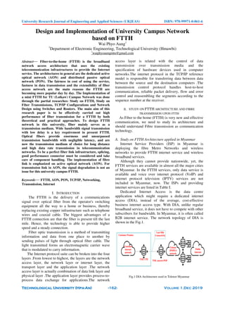
Dedicated Internet Access is the data centre
application which might require a dedicated internet
access (DIA), instead of the average, cost-effective
business internet access type. With DIA, unlike regular
broadband service, it does not have to compete with other
subscribers for bandwidth. In Myanmar, it is often called
B2B internet service. The network topology of DIA is
shown in the Fig.1.
Customer
internet
network
Customer Premise
TML CPE
Last Mile
Connectivity
TML nearest POP
Telenor
IPMPLS
network
Public
Internet
Fig.1 DIA Architecture used in Telenor Myanmar
2. University Research Journal of Engineering and Applied Sciences (URJEAS) ISBN: 978-99971-0-861-6
Technological University (Hpa-An) -163- Volume 1,Dec 2019
TABLE I
LIST OF ISPS AND PROVIDING INTERNET SERVICES IN MYANMAR
No
.
ISP Name Offering Internet Services
1 MPT
Dedicated
Internet Access
FTTH ADSL
2
Telenor
Myanmar
Dedicated
Internet Access
FTTH
Wireless
Broadband
3
Ooredoo
Myanmar
Dedicated
Internet Access
FTTH
Wireless
Broadband
4 Mytel
Dedicated
Internet Access
FTTH
5
5BB
Broadband
FTTH
Wireless
Broadband
6
Myanmar
Net
FTTH
Wireless
Wifi
7
Yatanarpon
Teleport
Dedicated
Internet Access
FTTH
8
Global
Technology
Dedicated
Internet Access
FTTH
9 Fortune FTTH
10 Horizon FTTH
Wireless
Wi-Fi
11 Unilink
Dedicated
Internet Access
FTTH
12
Myanmar
Network
Wireless
Wi-Fi
13 Welink FTTH
14
Myanmar
Speed Net
Dedicated
Internet Access
FTTH
15
Ananda
Livemore
LTE 4G+
Wi-Fi
16
Net Core
Internet
FTTH
Fig.2 PON Architecture of MPT
Passive Optical Network (PON) Architecture of MPT
is shown in Fig. 2. Since MPT is the oldest and largest
operator in Myanmar, they have existing exchange
building and access nodes in nationwide. Therefore, MPT
usually deploys the fiber based access networks both DIA
and FTTH services in the straight. MPT used various
installation methods while deploying the fiber networks
as followed:
• Direct buried
• Duct and
• Aerial.
In the downstream transmission, the laser wavelength
which is 1490nm for data services is sent to end user via
the PON networks. The light signal from OLT passes
through feeder cable and to primary fiber concentration
point (FCP) . When the light signal reached to Primary
FCP, the optical splitter divided and separates the optical
power with the predetermined ratios to the respective
paths to Secondary FCP. On the same operation, the
Secondary FCP splits the power to the desired ONUs.
The built-in media converter of ONUs transmits the
signal to the end user devices. The configuration of
ONUs is done in Center Office and monitors the services
status at the NMS.
The active optical network (AON) architecture which
is one of the FTTH network deployment systems is a
point to point (P2P) structure. This architecture is used in
Mytel. The AON of Mytel was shown in Fig.3. The
uplink signal from the OLT passes through the feeder
cable and enters to Electrical switching equipment (Site
Router). The relative signal is transmitted via the optical
port putting small form factor plausible (SFP0 module in
Site Router to the relative customer with the help of the
distribution fibre. When the signal reaches to media
converter at customer site, media converter converts the
optical signal to electrical signal which are enable to use
with the connected devices. The user request information
will be reversed direction.
Fig. 3. AON Architecture of Mytel
For Expected Future FTTH services in Myanmar; as the
growing of technology is day by day, various demands on
high speed internet access for the business and other
productivities are also emerged. FTTH is future proof
solution for providing broadband services such as Video
on demand, Online Gaming, HD TV and VoIP.
Nowadays, we can expect the HDTV and VoIP services
in the near future, although we can get only data services
from FTTH. The E-government system of Myanmar is on
the way and 5G is coming soon. Upon these, demand of
high speed internet services and new exciting and
innovation technologies are flying to Myanmar.
Study on Fibre transmission upon FTTH
Fiber optic transmission has various advantages over
other transmission methods like copper or radio
transmission. Fiber optic cablewhich is lighter, smaller
and more flexible than copper can transmit signals with
3. University Research Journal of Engineering and Applied Sciences (URJEAS) ISBN: 978-99971-0-861-6
Technological University (Hpa-An) -164- Volume 1,Dec 2019
faster speed over longer distance. However, many factors
can influence the performance of fiber optic. To ensure
the nice and stable performance of the fiber optic, many
issues are to be considered. Fiber optic loss is a negligible
issue among them, and it has been a top priority for many
engineers to consider during selecting and handling fiber
optic. This article will offer detailed information of losses
in optical fiber.
Optical transceiver module is an integrated circuit (IC)
that transmits and receives data in both directions
independently. The device combines a transmitter and
receiver into a single module, converting electrical
signals into optical signals to allow these signals to be
efficiently transferred on fiber-optic cables from server to
server. The transmitter converts an electrical input to an
optical output from a laser diode. Light from the end of
the fiber is coupled to a receiver, and then a detector
converts light into an electrical signal, which is
conditioned for use by the receiving equipment.
Fiber optic transceiver consists of a transmitter,
receiver, optical components and a chip. Among which
the chip is usually regarded as the heart of a fiber optic
module. Moreover, the transceiver can be made with
more compact size, enabling an overall footprint of
servers to decrease, makes data centers smaller and more
streamlined while maintaining high port density. On the
other hand, smaller size means less power consumption
and lower cost.
Fig. 4. Optical to Electrical Conversion Block Diagram
The optical to electrical converter which tells the
receiver when to be received, this part is important in
attempting to figure out when the optical lasers are in the
desired mode for reflectivity. These times are when the
optical signal from the laser and the reflected signal have
travelled the “same” optical length or a difference in
length that is less than a coherence length. Secondary part
of this application is that the transition time also must be
accounted for. This transition time there might be false
times when the receiver is signalled to receive. Therefore,
the optical to electrical converter must account and hold
while the lasers are in transition mode. Photodiodes will
be used to translate the optical laser signal into a current
signal. This current signal will be converted to a voltage
signal. After that the two voltage signals will be
converted to single signal. This signal will then be
compared with ground to determine when zero crossings
of the input signals have occurred.
Fig. 5 Electrical to Optical Conversion Block Diagram
In electrical to optical conversion, there are two parts
(buffer and driver) coupled to each other in series. A
common- collector buffer amplifier has high input
impedance and low output impedance. The input of
summing circuit is connected to the high impedance of
common-collector amplifier, and the output if then
connected to an external load. The common-emitter-with
a resistance amplifier is to drive the optical source and
convert the signal from the electrical form into optical
form using the intensity modulation.
For single mode fibre optic cable speed, no matter
data rate is at 100 Mbps, the transmission distance can
reach up to 5km. Typically, the multimode fibre optic
cable speed and the transmitting distance limits are 100
Mbps for distance up to 2 km, Gbps up to 1000m, and 10
Gbps up to 550 m.
TABLE II
DISTANCES OF SINGLE MODE AND MULTI MODE FIBRE CABLE
Quantity Single Mode
Fibre Cable
Multimode
Fibber Cable
Core Diameter 9/10 µm 50/62.5 µm
Working Wavelengths 1310/1550 nm 850/1310 nm
Transmission Distance Short (5km) Long (2km)
The process steps of fusion splicing of Fibre optic
cable involves stripping, cleaning and cleaving of the two
fibre ends.
Fig.6 Fusion Splicing Processes of Fiber Optic Cable
4. University Research Journal of Engineering and Applied Sciences (URJEAS) ISBN: 978-99971-0-861-6
Technological University (Hpa-An) -165- Volume 1,Dec 2019
III. TECHNICAL APPROACHES TO IMPLEMENT A CAMPUS
NETWORK USING TCP/IP, SWITCHES AND ROUTERS
The design consideration and practical implementation
was done for TU (Loikaw) Campus. Two main processes,
TCP/IP configuration and Switches and Routers
installation are to be carried out.
F. TCP/IP Configuration Process
Network Infrastructure Drawing for EC Department,
1st
floor Classrooms, 2nd
Classrooms and Library Room is
considered as shown in Fig.7.
Fig.7 Network Infrastructure Consideration
The fiber access from the internet service provider
firstly enters to the fiber termination box, then to the
media converter and the network cable out of the media
converter is being entered into the ToToLink
router/modem. But, the bandwidth amount given by the
ISP is very weak compared to the amount of users in
campus area networks. Therefore, a Mikrotik router is
added to boost the amount of bandwidth. The router used
is MikrotikRB951Ui-2nD and it has only five ports,
Internet POE In, Internet POE Out and the three LAN
ports. The LAN ports 2 and 3 are enough for the two
main PCs inside the principal room via network cables.
From LAN 4, the boosted bandwidth is shared out of the
Mikrotik router to the 24-Port switch device of the EC
Department.
Fig.8 Network Setup of Mikrotik Router with PC for Configuration
The reason the switch is used is that it can capture the
signal from the Mikrotik router, multiply the signal to the
signals of the same bandwidth and distribute to its
outgoing ports without causing signal strength to
decrease. Therefore, the switch in this case is more like a
hub or a repeater. The hub in networking is nothing more
than a repeater because these devices are used to further
extend the shared network. The service is then shared
from the switch to the PCs located inside the EC
Department via Ethernet cables and to the wireless
accessible electronic devices via TPLink access point.
The remaining LAN Ethernet ports of the 24-Port switch
are connected to CPEs of the 1st-floor classrooms, the
2nd-floor classrooms and the library room. The amount
of users or students that a single Ubiquity loco nano
station M2 CPE device can serve is from 25 up to 40.
Therefore, one CPE is located between the centre point of
two classrooms.
The reach ability of a single CPE device is up to 5 km
and its beamwidth is wider compared to normal wireless
emitting device such as TP Link inside the EC
Department. Therefore, the radio waves emitted by the
outdoor CPE can reach to more range, even inside walls
of the classrooms and the CPE device itself can support
many more users compared to TPLink access point. So,
the outdoor CPEs are the most suitable option for sharing
the wireless access to the classrooms. The detail step by
step configuration processes are shown in Fig. 8 to Fig.
12.
Fig. 9 Configuring Wireless Access
Fig.10 Creating Security Profile for SSID:TULOIKAW
5. University Research Journal of Engineering and Applied Sciences (URJEAS) ISBN: 978-99971-0-861-6
Technological University (Hpa-An) -166- Volume 1,Dec 2019
Fig. 11 Network Setup of Outdoor CPE with PC
Fig.12 Giving the First CPE Static IP Address
G. Switches and Routers for TU(Loikaw) Campus
Network
The Proposed Design of Campus Network considered
is as shown in Fig.13. The DES -1016D switch offers an
economical way for SOHO and small to medium
businesses to benefit from high speed networking. It
provides twenty -four ports for easy expansion of network
and a quick way to upgrade network to fast Ethernet
connectivity. The switches speed file transfer times,
improve slow sluggish networks, keep vital business
applications available, and help employees respond more
quickly to customers and each other. This power -saving
feature automatically puts the switch into a low-power
idle state when the switch cultivation is zero, allowing
lowering energy usage and saving on energy costs.
Mikrotik CCR1016-12G Router is available with a 1U
rack mount case, has twelve Gigabit Ethernet ports, a
serial console cable and a USB port. The CCR1016-12G
has two SODIMM slots, by default it is shipped with
2GB of RAM, but has no memory limit in Router OS
(will accept and utilize 16GB or more). It comes with
power supply and 1U rack mount case.
The Dynamic Host Configuration Protocol (DHCP)
provides a framework for passing configuration
information to hosts on a TCP/IP network. A DHCP
client is an Internet host using DHCP to obtain
configuration parameters such as an IP address. The basic
steps that occur when a DHCP client requests an IP
address from a DHCP server as shown in Fig. 14.
Fig.13 Proposed Campus Network
6. University Research Journal of Engineering and Applied Sciences (URJEAS) ISBN: 978-99971-0-861-6
Technological University (Hpa-An) -167- Volume 1,Dec 2019
The client, Host A, sends a DHCP DISCOVER
broadcast message to locate a DHCP server. A DHCP
server offers configuration parameters to the client in a
DHCP OFFER uncast message. A DHCP server is a
network server that automatically provides and assigns IP
addresses.
Fig. 14 Dynamic Host Configuration Protocol (DHCP)
Ubiquiti Aircube router can improve the existing
wireless connections Great Replacement for the Ubiquiti
Air Router that has now been EOL. It has the following
features;
• (4) Gigabit Ethernet Ports
• 24V POE pass through for airMAX CPE
• Dual-Band, 802.11ac, 2x2 MIMO Technology
• Up to 300 Mbps in the 2.4 GHz Radio Band
• Up to 866.7 Mbps in the 5 GHz Radio Band
• Powered by 24V Passive POE or Included Power
Adapter
• Great Replacement for the Ubiquiti Aircube
Router that has now been EOL.
TABLE III
THE SPECIFICATIONS OF TP-LINK TL WA901ND
Quantity Specifications
Standards IEEE 802.11n. IEEE 802.11g, IEEE
802.11b
Interface One Ethernet Port (RJ45)
Supporting Passive PoE
Wireless Signal
Rates With
Automatic Fallback
11n: Up to 300Mbps (dynamic)
11g: Up to 54Mbps (dynamic)
11b: Up to 11Mbps (dynamic)
Frequency Range 2.4-2.4835GHz
Wireless Transmit
Power
20dBm(Max)
Antenna 4dBi detachable Omni directional
antenna*3
Modulation
Technology
IEEE 802.11b: DQPSK, DBPSK,
DSSS and CCK
IEEE 802.11g: BPSK,
QPSK,16QAM, 64QAM OFDM
Receiver Sensitivity
270M: -68dBm@10%PER
1300M: -68dBm@10%PER
11M: -85dBm@8%PER
6M: -88dBm@10%PER
1M: -90dBm@8%PER
256K: -105dBm@8%PER
Power Supply Unit Input: localized to
country of sale
Output:12VDC/1A Switching
.
The TP-Link Wireless N access point TL-WA901ND
is designed to establish or expand a saleable high-speed
wireless N network or to connect multiple Ethernet
enabled devices such as digital media adapters, printers or
network attached storage devices to a wireless network.
Table III shows the specifications of TP-Link TL-
WA901ND.
IV. IMPLEMENTATION PROCESSES, TEST AND RESULTS
The Implementation processes that accomplished the
real-time Campus Network by Networking
Technological Approaches are as the following steps.
The testing results of implementation records are shown
by the following Fig. 15 to 23.
Step1. Understanding the FTTH Architecture and
Applications.
Step2. Understanding Fiber Transmission Theory
Step3. Understanding TCP/IP Configuration
Techniques
Step4. Surveying AON site and PON site on
ground
Step5. Comparison upon AON and PON under
FTTH
Step6. Design Consideration of a FTTH based
Campus Network
Step7. Analysis Proposed Design to be Optimum
Step8. Decision for a desire Campus Network
Design
Fig. 15 Spliced Fibre Covered with Sleeve
Fig. 16 Protection of Splice able Fibres in User Box
7. University Research Journal of Engineering and Applied Sciences (URJEAS) ISBN: 978-99971-0-861-6
Technological University (Hpa-An) -168- Volume 1,Dec 2019
Fig. 17 LC Connector Plug to Module
Fig.18 OTDR Testing
Fig. 19 Network Cable from LAN Port of ToToLink Router to PoE in
Port of Mikrotik Router
Fig. 20 Network Cable from One LAN Port into 24-Port Switch
Fig. 21 Connection of Media Converter and Mikrotik Router
Fig. 22 Cisco Unmanaged Switch Connected to other Devices
Fig. 23 Connection from Cisco Switch to Distribute Wireless
Connection
V. DISCUSSIONS, CONCLUSION AND RECOMMENDATIONS
The real-time implementation of a FTTH based
Campus Network for TU (Loikaw) was considered
designed and makes some comparisons. Technical
approaches through this project were to be published in
this paper as part of research work.
As technical conclusion, when the network devices
used and other network services are compared to the
TCP/IP layered model, the following observations are
found. The Network Access methods in this project are
Ethernet 802.3 local area networks and Wireless 802.11
networks. The TPLink and the ToToLink routers do the
logical IP addressing of network devices connected to it
and routing of data packets from the inside networks to
the outside internetworks. Therefore, these devices are
working on the Internet layer of the TCP/IP protocol
suite. For the reliable transmission of important files
between each user, the Transmission Control Protocol
(TCP) of the Transport layers supported by the host
devices connected to the university campus area
networks. For audio and video live streaming for tutorial
and learning purposes, the User Datagram Protocol
(UDP) of the Transport layer is also being supported. The
application layered protocols of the host devices within
8. University Research Journal of Engineering and Applied Sciences (URJEAS) ISBN: 978-99971-0-861-6
Technological University (Hpa-An) -169- Volume 1,Dec 2019
the campus area networks, such as DNS, HTTP, FTP,
SMTP and POP3, enable accessing to the network
resources, web pages, file related services and enable
sending and receiving mails.
As future work recommendation, the next level of
Internet is the Internet of Things (IoT). The IoT is the
convergence of micro-electromechanical systems
(MEMS), Wireless connectivity, the Internet and micro
services. As a result of combination of these systems, the
IoT helps people live with complete control over their
lives and also helps in almost every fields related with
industrial manufacturing, businesses, education, health
care, weather, finance, retail and many others. The IoT
systems and applications can be implemented in the
university campus area for school security, attendance
monitoring, smoke detecting, network connected smart
classrooms, students’ physical health and task-based
learning.
ACKNOWLEDGMENT
The real-time implementation of a FTTH based
Campus Network for TU (Loikaw) was considered,
designed and makes some comparisons. The Special
thanks are all the persons that involved in this project:
Pro-rector, VIEC students of 2018-19 academic years and
Teachers from EcE Department, TU (Loikaw).
REFERENCES
[1] Jeffrey Mogul; Jon Postel. Internet Standard
Subnetting Procedure, August 1985
[2] R. Braden (ed.), Requirements for Internet Hosts –
Application and Support, October 1989
[3] Y. Rekhter; T. Li. Architecture for IP Address
Allocation with CIDR, September 1993.
[4] Almquist, Towards Requirements for IP Routers
RFC 1716, P. November 1994.
[5] Y.Rekhter; B. Moskowitz; D.Karrenberg; G. J. de
Groot; E. Lear. Address Allocation for Private
Internets, February 1996.
[6] Grigonis, Richard. Computer Telepony-
encyclopaedia.CMP.p.331.2000
[7] S. Waldbusser, Remote Network Monitoring
Management Information Base, May 2000.
[8] Berouz, A .Data Communication and Networks,
(2002).
[9] Dorms, Ralph; Lemon, Ted. The DHCP Handbook,
(2003).
[10] J.C. Klensin, J. Klensin. "Role of the Domain Name
System (DNS)", Feburary 2003.
[11] Kozierok, Charles M. TheTCP/IP Guide: A
Comprehensive, Illustrated Internet Protocols
Reference, (1 January 2005).
[12] Barry, G.B. Computer Systems and Networks,
(2007).
[13] Network Infrastructure Committee, FTTH
Infrastructure Components and Deployment
Methods, 2007.
[14] William, S. Data and Computer Communications
(8th Edition), (2007)
[15] John M. Senior, Optical Fiber Communications
Principle and Practice Third Edition2009.
[16] Tamara Dean. Network+ Guide to Networks.
Cengage Learning. P. 272. 2009.
[17] Tim Poulus, “FTTH network: Active Ethernet versus
Passive Optical Networking And point-to-point vs.
point-to-multipoint”, 17 November 2010.
[18] Berouz A. Forouzan. Data Communication and
Networking (5th Edition), (2012).
[19] Deeksha Kocher, “Investigation of FTTH
Architecture Based on Passive Optical Networks”,
2012.
[20] HaydarMohammed, “Fiber-To-The-Home (FTTH)
High speed Internet Broadband”,8 July 2012.
[21] Marke Jackson, “The Definition of UK Superfast
Next Generation Broadband”, 3 May 2012.
[22] Clarkson, Michael. "Access Control". Cornell
University. Retrieved 2013-04-08.
[23] Ed Gubbins, “Active Ethernet grows in PON’s
shadow”, 13 May 2008, retrieved 12 July 2013.
[24] Grünbacher, Andreas"Native NFSv4 ACLs on
Linux". SUSE. Archived from the original on 2013-
06-20.
[25] Tetz E (n.d), Pros and Cons of Static Routing,
accessed 5 November 2013.
[26] David Wetherall, J. WA: Computer Networks (5th
Edition). University of Washington Seattle, (2014).
[27] Heath Nick, “Could ultrafast broadband over copper
speed the rollout of gigabit Internet?” 26 September
2014.
[28] Karin Ahl, FTTH Handbook, February 18, 2014.
[29] Thayumanavan Sridhar (September 1998). "The
Internet Protocol Journal - Volume 1, No. 2: Layer 2
and Layer 3 Switch Evolution". Cisco Systems.
Retrieved 2015-08-11.
[30] Matt Hurst, Fusion Splicing vs. Mechanical Splicing,
February 25, 2016.
[31] Rong Zhao and Michaela Fischer, “FTTH
Handbook”, Edition 7, FTTH Council Europe, 2016.