

Recommended
More Related Content
What's hot
What's hot (20)
Similar to デザインキット・DCモータ制御回路のインデックス
Similar to デザインキット・DCモータ制御回路のインデックス (20)
More from Tsuyoshi Horigome
More from Tsuyoshi Horigome (20)
Recently uploaded
Recently uploaded (20)
デザインキット・DCモータ制御回路のインデックス
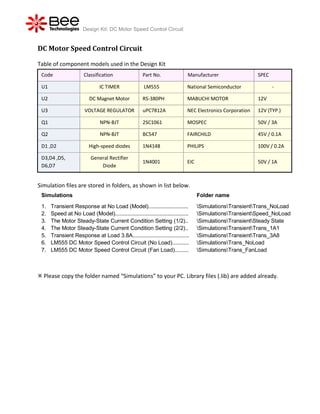
- 1. Design Kit: DC Motor Speed Control Circuit DC Motor Speed Control Circuit Table of component models used in the Design Kit Code Classification Part No. Manufacturer SPEC U1 IC TIMER LM555 National Semiconductor - U2 DC Magnet Motor RS-380PH MABUCHI MOTOR 12V U3 VOLTAGE REGULATOR uPC7812A NEC Electronics Corporation 12V (TYP.) Q1 NPN-BJT 2SC1061 MOSPEC 50V / 3A Q2 NPN-BJT BC547 FAIRCHILD 45V / 0.1A D1 ,D2 High-speed diodes 1N4148 PHILIPS 100V / 0.2A D3,D4 ,D5, General Rectifier 1N4001 EIC 50V / 1A D6,D7 Diode Simulation files are stored in folders, as shown in list below. Simulations Folder name 1. Transient Response at No Load (Model).......................... SimulationsTransientTrans_NoLoad 2. Speed at No Load (Model)................................................ SimulationsTransientSpeed_NoLoad 3. The Motor Steady-State Current Condition Setting (1/2).. SimulationsTransientSteady State 4. The Motor Steady-State Current Condition Setting (2/2).. SimulationsTransientTrans_1A1 5. Transient Response at Load 3.8A..................................... SimulationsTransientTrans_3A8 6. LM555 DC Motor Speed Control Circuit (No Load)........... SimulationsTrans_NoLoad 7. LM555 DC Motor Speed Control Circuit (Fan Load)......... SimulationsTrans_FanLoad Please copy the folder named “Simulations” to your PC. Library files (.lib) are added already.
- 2. Design Kit: DC Motor Speed Control Circuit Design document: DC Motor Speed Control Circuit Contents 1. The Simulation of DC Motor Control Circuit............................................................................... 2. DC Motor Model 2.1 Manufacturer Specification................................................................................................... 2.2 Torque Constant and Back EMF Constant........................................................................... 2.3 The Armature Inductance and Resistance........................................................................... 2.4 The DC Motor Equivalent Circuit.......................................................................................... 2.5 Transient Response at No Load........................................................................................... 2.6 Transient Response at No Load (Model).............................................................................. 2.7 Speed at No Load (Model)................................................................................................... 2.8 The Motor Steady-State Current Condition Setting.............................................................. 2.9 Transient Response at Load 3.8A (Measurement vs. Simulation)....................................... 3. LM555 DC Motor Speed Control Circuit (No Load)................................................................ 3.1 Rectified dc voltage with ripple............................................................................................. 3.2 IC 555 Output Pulse Voltage................................................................................................ 3.3 Transistor Q2: VCE.............................................................................................................. 3.4 Transistor Q1: VCE, IC......................................................................................................... 3.5 Motor Voltage and Current................................................................................................... 4. LM555 DC Motor Speed Control Circuit (Fan Load).............................................................. 4.1 Rectified dc voltage with ripple............................................................................................. 4.2 IC 555 Output Pulse Voltage................................................................................................ 4.3 Transistor Q2: VCE.............................................................................................................. 4.4 Transistor Q1: VCE, IC......................................................................................................... 4.5 Motor Voltage and Current................................................................................................... Simulations index Simulation Settings