Distance Estimation based on Color-Block: A Simple Big-O Analysis
patentpdfhealthcare
1. Patents
Publication number US20130329217 A1
Publication type Application
Application number US 13/493,083
Publication date Dec 12, 2013
Filing date Jun 11, 2012
Priority date Jun 11, 2012
Inventors Shikui Yan, Thomas Bruckbauer, Travis
Pless, Robert Scott Beach, Sam Griffin
Original Assignee Siemens Medical Solutions Usa, Inc.
Export Citation BiBTeX, EndNote, RefMan
Patent Citations (4), Classifications (6), Legal Events (1)
External Links: USPTO, USPTO Assignment, Espacenet
CLAIMS (20)
What is claimed is:
1. A system for aligning a bed of an imaging system with an imaging plane,
comprising:
a laser device which generates a laser beam;
a target element having a target detecting surface and a collimator hole,
wherein the laser beam is transmitted through the collimator hole; and
a reflective element which receives the laser beam, the reflective element
having a reflective detecting surface for detecting a first position of the laser
beam wherein the first position is used to adjust at least one first parameter
of the bed and wherein the laser beam is reflected to the target detecting
surface to detect a second position of the laser beam wherein the second
position is used to adjust at least one second parameter of the bed.
2. The system according to claim 1, wherein the reflecting and target
detecting surfaces each include a predetermined pattern for detecting
the first and second positions, respectively, of the laser beam.
3. The system according to claim 1, wherein the reflective and target
detecting surfaces each include a cross hair pattern for detecting the
first and second positions, respectively, of the laser beam.
4. The system according to claim 1, wherein the reflective and target
detecting surfaces each include light sensitive material or device for
detecting the first and second positions, respectively, of the laser
beam.
Laser System for Aligning a Bed Transport
Mechanism in an Imaging System
US 20130329217 A1
ABSTRACT
A system for aligning a bed of an imaging system with an imaging plane. The
system includes a laser device which generates a laser beam and a target
element having a target detecting surface. The system also includes a reflective
element which receives the laser beam. The reflective element includes a
reflective detecting surface for detecting a first position of the laser beam. A first
parameter of the bed is adjusted until the laser beam is positioned on a first
center portion of the reflective detecting surface. In addition, the laser beam is
reflected to the target detecting surface to detect a second position of the laser beam. A second parameter of the bed is adjusted until the laser beam is positioned
on a second center portion of the target detecting surface to orient the bed substantially perpendicular to the imaging plane.
DESCRIPTION
FIELD OF THE INVENTION
This invention relates to a system and method for aligning a transport
mechanism for moving a bed, table, or imaging device in an imaging system
having an imaging plane, and more particularly, to a laser system having a
target element and a reflective element for detecting the position of a laser
beam wherein a position of the bed is adjusted based on detected laser beam
positions.
BACKGROUND OF THE INVENTION
It is important that a bed used to accommodate or hold an object to be scanned
by an imaging system be correctly aligned with an imaging plane of the system
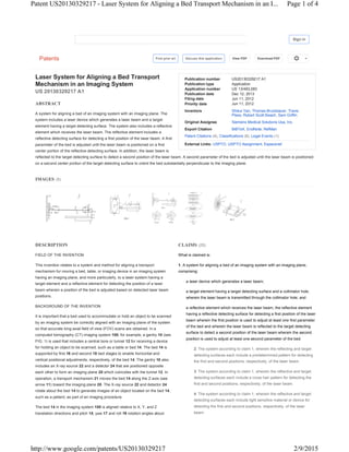
so that accurate long-axial field of view (FOV) scans are obtained. In a
computed tomography (CT) imaging system 100, for example, a gantry 10 (see
FIG. 1) is used that includes a central bore or tunnel 12 for receiving a device
for holding an object to be scanned, such as a table or bed 14. The bed 14 is
supported by first 16 and second 18 bed stages to enable horizontal and
vertical positional adjustments, respectively, of the bed 14. The gantry 10 also
includes an X-ray source 22 and a detector 24 that are positioned opposite
each other to form an imaging plane 20 which coincides with the tunnel 12. In
operation, a transport mechanism 21 moves the bed 14 along the Z-axis (see
arrow 11) toward the imaging plane 20. The X-ray source 22 and detector 24
rotate about the bed 14 to generate images of an object located on the bed 14,
such as a patient, as part of an imaging procedure.
The bed 14 in the imaging system 100 is aligned relative to X, Y, and Z
translation directions and pitch 15, yaw 17 and roll 19 rotation angles about
Find prior art Discuss this application View PDF Download PDF
IMAGES (5)
Sign in
Page 1 of 4Patent US20130329217 - Laser System for Aligning a Bed Transport Mechanism in an I...
2/9/2015http://www.google.com/patents/US20130329217
2. 5. The system according to claim 1, wherein adjustment of at least one
first parameter of the bed includes X and Y positions.
6. The system according to claim 1, wherein adjustment of at least one
second parameter of the bed includes pitch and yaw rotation positions.
7. The system according to claim 1, wherein laser device utilizes a
non-amplified, light emitting diode (LED) laser source.
8. The system according to claim 1, wherein the imaging system is a
computed tomography imaging system.
9. The system according to claim 1, wherein the target element is
mounted to the bed and the reflective element is mounted to a gantry
of the imaging system wherein the reflective detecting surface is
oriented substantially parallel to the imaging plane.
10. A system for aligning a bed of an imaging system with an imaging plane,
comprising:
a laser device which generates a laser beam;
a target element having a target detecting surface and a collimator hole,
wherein the laser beam is transmitted through the collimator hole; and
a reflective element which receives the laser beam, the reflective element
having a reflective detecting surface for detecting a first position of the laser
beam wherein at least one first parameter of the bed is adjusted until the
laser beam is positioned on a first center portion of the reflective detecting
surface and wherein the laser beam is reflected to the target detecting
surface to detect a second position of the laser beam wherein at least one
second parameter of the bed is adjusted until the laser beam is positioned
on a second center portion of the target detecting surface to orient the bed
substantially perpendicular to the imaging plane.
11. The system according to claim 10, wherein the first center portion
is approximately 3 mm in size.
12. The system according to claim 10, wherein the second center
portion is approximately 1 mm in size.
13. The system according to claim 10, wherein the reflecting and target
detecting surfaces each include a predetermined pattern for detecting
the first and second positions, respectively, of the laser beam.
14. The system according to claim 10, wherein the reflective and target
detecting surfaces each include a cross hair pattern for detecting the
first and second positions, respectively, of the laser beam.
15. The system according to claim 10, wherein the reflective and target
detecting surfaces each include light sensitive material or device for
detecting the first and second positions, respectively, of the laser
beam.
16. The system according to claim 10, wherein adjustment of at least
one first parameter of the bed includes X and Y positions.
17. The system according to claim 10, wherein adjustment of at least
one second parameter of the bed includes pitch and yaw rotation
positions.
18. The system according to claim 10, wherein the target element is
mounted to the bed and the reflective element is mounted to a gantry
of the imaging system wherein the reflective detecting surface is
oriented substantially parallel to the imaging plane.
19. The system according to claim 10, wherein laser device utilizes a
non-amplified, light emitting diode (LED) laser source.
three perpendicular axes. In many imaging systems, a manual multi-step
procedure is used wherein a bed alignment tool, protractor, machinist square
and other tools or devices are used to align the bed 14. In this procedure,
specific parameters for bed alignment are manually checked, and if the bed 14
is not aligned, adjustments are made to align the bed 14 whereupon bed
alignment is then rechecked. The process of checking bed alignment, making
adjustments to the alignment and rechecking the alignment is then repeated
until a desired alignment is achieved. However, this results in an iterative
process which is time consuming and takes experienced personnel
approximately six hours to complete.
SUMMARY OF THE INVENTION
A system for aligning a bed of an imaging system with an imaging plane is
disclosed. The system includes a laser device which generates a laser beam
and a target element having a target detecting surface and a collimator hole,
wherein the laser beam is transmitted through the collimator hole. The system
also includes a reflective element which receives the laser beam. The reflective
element includes a reflective detecting surface for detecting a first position of
the laser beam wherein at least one first parameter of the bed is adjusted until
the laser beam is positioned on a first center portion of the reflective detecting
surface. In addition, the laser beam is reflected to the target detecting surface to
detect a second position of the laser beam wherein at least one second
parameter of the bed is adjusted until the laser beam is positioned on a second
center portion of the target detecting surface to orient the bed substantially
perpendicular to the imaging plane.
BRIEF DESCRIPTION OF THE DRAWINGS
FIG. 1 depicts a gantry and bed arrangement for an imaging system.
FIG. 2 depicts a schematic of a laser system for aligning a bed of an imaging
system in accordance with the invention.
FIGS. 2A-2B depict first and second cross hair patterns formed on reflective
and target elements, respectively of the system.
FIG. 3 illustrates a calibration flow diagram for aligning the bed with the image
plane of the imaging system.
DESCRIPTION OF THE INVENTION
Before any embodiments of the invention are explained in detail, it is to be
understood that the invention is not limited in its application to the details of
construction and the arrangement of components set forth in the following
description or illustrated in the following drawings. The invention is capable of
other embodiments and of being practiced or of being carried out in various
ways. Also, it is to be understood that the phraseology and terminology used
herein is for the purpose of description and should not be regarded as limiting.
The use of “including,” “comprising,” or “having” and variations thereof herein is
meant to encompass the items listed thereafter and equivalents thereof as well
as additional items. Unless specified or limited otherwise, the terms “mounted,”
“connected,” “supported,” and “coupled” and variations thereof are used broadly
and encompass direct and indirect mountings, connections, supports, and
couplings. Further, “connected” and “coupled” are not restricted to physical or
mechanical connections or couplings. In the description below, like reference
numerals and labels are used to describe the same, similar or corresponding
parts in the several views of FIGS. 1-4.
Referring to FIG. 2, a schematic of a laser system 30 for aligning the bed 14 of
an imaging system in accordance with the invention is shown. The system 30
may be used in connection with the CT imaging system 100, for example, or
any other imaging system or scanner having an imaging plane that is oriented
substantially perpendicular to a bed 14. In addition, the imaging system may of
the type having a movable bed and a stationary imaging device or a stationary
bed and a movable imaging device and combinations thereof. Further, the
Page 2 of 4Patent US20130329217 - Laser System for Aligning a Bed Transport Mechanism in an I...
2/9/2015http://www.google.com/patents/US20130329217
3. 20. A method for aligning a bed of an imaging system with an imaging plane,
comprising:
generating a laser beam;
detecting a first position of the laser beam on a reflective detecting surface;
adjusting at least one first parameter of the bed until the laser beam is
positioned on a first center portion of the reflective detecting surface;
detecting a second position of the laser beam on a target detecting surface;
and
adjusting at least one second parameter of the bed until the laser beam is
positioned on a second center portion of the target detecting surface to
orient the bed substantially perpendicular to the imaging plane.
system 30 may be used in clinical imaging systems and systems having a
higher resolution such as preclinical imaging systems including the Siemens
Inveon CT imaging system. The system 30 includes a laser device 32 that is
removably mounted on the second bed stage 18 and a target element 34
removably mounted on the second bed stage 18 in front of the laser device 32.
The system 30 also includes a reflective element 36 having a first surface 44.
Referring to FIG. 2A, a front view of the reflective element 36 along view line
2A-2A of FIG. 2 is shown. The first surface 44 includes a first cross hair pattern
38 having a reflective center portion 40. In one embodiment, the reflective
center portion 40 is approximately 3 mm in size. Referring back to FIG. 2, the
reflective element 36 is attached to a mounting fixture 42 by bonding, for
example. The mounting fixture 42 is removably attached to the gantry 10 such
that a plane 45 of the first surface 44 is substantially parallel to the imaging
plane 20.
FIG. 2B is a front view of the target element 34 along view line 2B-2B of FIG. 2.
The target element 34 includes a second surface 47 having a second cross hair
pattern 46 and a collimation hole 48 located in a center portion 49 of the second
cross hair pattern 46. In one embodiment, the collimation hole 48 is approximately 1 mm in size. The first 38 and second
46 cross hair patterns may each include indicia to enable measurement of the location of a laser beam spot formed on the
first 44 and second 47 surfaces. Alternatively, the first 44 and second 47 surfaces each include light sensitive material or
device for detecting a location of a laser beam spot on the surfaces 44,47. The first 44 and second 47 surfaces face each
other and may be spaced approximately 100 cm from each other. Alternatively, other predetermined patterns, such as
bullseye and other patterns, may be formed on the first 44 and second 47 surfaces instead of the first 38 and second 46
cross hair patterns.
In accordance with the invention, a laser beam 50 generated by the laser device 32 is first aligned with the Z-axis. The
laser beam is then transmitted through the collimation hole 48 to form a collimated laser beam 52. The collimated laser
beam 52 then impinges on the reflective center portion 40 and forms a first beam spot 54 on the first surface 44. If the first
beam spot 54 is not located on the reflective center portion 40, an offset is indicated in either or both the X and Y
directions, depending on the location of the first beam spot 54. The offset is measured by using the first cross hair pattern
38. Using the measured offset, the bed 14 is then correspondingly adjusted in either the X direction or the Y direction, or
both the X and Y directions, as needed, so that the first beam spot 54 impinges on the reflective center portion 40 as
shown in FIG. 2A.
The laser beam 52 is then reflected by the reflective center portion 40 back to the target element 34 thus forming a second
beam spot 56 on the second surface 47. If the second beam spot 56 is not located on the center portion 49 of the second
cross hair pattern 46, as offset is indicated. The bed 14 is then correspondingly adjusted so that the second beam spot 56
impinges on the center portion 49. This ensures that the bed axis (i.e. the Z axis) and the first surface 44 are substantially
perpendicular to each other thus adjusting pitch and yaw rotation angles to zero. The second beam spot 56 then coincides
with the collimation hole 48. In one embodiment, the laser device 32 utilizes a non-amplified, light emitting diode (LED)
based laser source such that the laser beam 50 is not affected by the back reflection into the collimator hole 48. Further,
adjustment of the second beam spot 56 may be performed dynamically by tracking the position of the second beam spot
56 on the second surface 47 as the bed 14 moves.
Referring to FIG. 3, a calibration flow diagram 60 for the current invention is shown. The bed alignment process begins at
step 62 and proceeds to step 64 wherein the reflective element 36 is mounted on the gantry 10 and the target element 34
is mounted on the bed 14. At step 66, a coarse adjustment of the bed 14 is performed to ensure that the first beam spot 54
impinges on the reflective element 36. At step 68, a coarse adjustment of the bed 14 is performed to ensure that the
second beam spot 56 impinges on the target element 34. At step 66, a determination is made as to whether the first beam
spot 54 impinges on the reflective center portion 40 of the reflective element 36. If the first beam spot 54 does not impinge
on the reflective center portion 40, a fine adjustment of the bed 14 is performed. Once the first beam spot 54 impinges on
the reflective center portion 40, the process moves to step 70 wherein a determination is made as to whether the second
beam spot 56 impinges on the collimator hole 48. If the second beam spot 54 does not impinge on the collimator hole 48,
a fine adjustment of the bed 14 is performed. Once the second beam spot 54 impinges on the collimator hole 48, the
calibration process is complete at step 70.
Use of the invention results in a bed alignment process that is faster, more accurate and more reliable. In particular, the
system 30 has resulted in a reduction of the time needed to align the bed 14 from approximately six hours to
approximately five minutes. Further, tests have shown that the system 30 reduces measurement error by approximately
one half. In addition, accuracy is improved to approximately ±0.031 degrees from approximately ±0.15 degrees.
Therefore, the system 30 provides a collimated, double targeted, reflective (CTDR) laser system for enabling alignment of
a bed used in a medical imaging system. The CDTR system is relatively low cost and easy to assemble. In addition, the
system 30 provides instant feedback during use since the location of second beam spot 56 on the second surface 47 of
Page 3 of 4Patent US20130329217 - Laser System for Aligning a Bed Transport Mechanism in an I...
2/9/2015http://www.google.com/patents/US20130329217
4. the target element 34 is readily observable as the bed 14 is moving. Further, the CDTR system enables the calibration of
five degrees of freedom (i.e. translation X and Y directions and pitch, yaw and roll rotations if double sources are used)
using a single apparatus.
Referring to FIG. 4, a schematic of an alternate embodiment of the invention is shown. In this embodiment, the laser
device 32 is replaced by an optical alignment device 80. The device 80 includes first 82 and second 84 substantially
V-shaped grooves formed in first 86 and second 88 support blocks that are mounted to an attachment plate 90. The
attachment plate 90 is removably mounted to the bed 14 such that the first 82 and second 84 grooves are aligned with the
Z-axis of the imaging system 100. In addition, an alignment plate 92 is removably attached to the gantry 10. The alignment
plate 92 includes a predetermined pattern with indicia, such as a crosshair or bullseye 94 pattern used to align the bed 14.
In order to align the bed 14, an operator establishes a line of sight through the first 82 and second 84 grooves to determine
whether the bed 14 is aligned. If a center portion 96 of the bullseye pattern 94 is visible through the first 82 and second 84
grooves, the bed 14 is aligned. If the center portion 96 is not visible, the bed 14 is adjusted until the center portion 96 of
the bullseye pattern 94 is visible through the first 82 and second 84 grooves. In yet another embodiment, an aperture hole
may be used instead of the first 82 and second 84 grooves to view the bullseye pattern 94.
While the invention has been described in conjunction with specific embodiments, it is evident that many alternatives,
modifications, permutations and variations will become apparent to those skilled in the art in light of the foregoing
description. Accordingly, it is intended that the present invention embrace all such alternatives, modifications and
variations.
PATENT CITATIONS
Cited Patent Filing date Publication date Applicant Title
US3628868 * Sep 9, 1969 Dec 21, 1971 Us Army Laser boresighting method and apparatus
US6565227 * Nov 13, 2001 May 20, 2003 Greg Davis Method and device for tool alignment
US7331113 * Apr 19, 2007 Feb 19, 2008 Algird Patrick Tool alignment device
US7456945 * Oct 24, 2003 Nov 25, 2008 Finisar Corporation Photonic device package with aligned lens cap
* Cited by examiner
CLASSIFICATIONS
U.S. Classification 356/138, 356/400
International Classification G01B11/14, G01B11/26
Cooperative Classification G01B11/272, G01B11/26
LEGAL EVENTS
Date Code Event Description
Jun 11, 2012 AS Assignment
Free format text: ASSIGNMENT OF ASSIGNORS INTEREST;ASSIGNORS:YAN, SHIKUI;BRUCKBAUER,
THOMAS;PLESS, TRAVIS;AND OTHERS;SIGNING DATES FROM 20120531 TO
20120607;REEL/FRAME:028350/0993
Owner name: SIEMENS MEDICAL SOLUTIONS USA, INC., PENNSYLVANIA
Google Home - Sitemap - USPTO Bulk Downloads - Privacy Policy - Terms of Service - About Google Patents - Send Feedback
Data provided by IFI CLAIMS Patent Services
Page 4 of 4Patent US20130329217 - Laser System for Aligning a Bed Transport Mechanism in an I...
2/9/2015http://www.google.com/patents/US20130329217