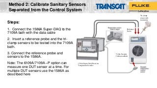
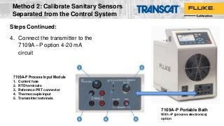
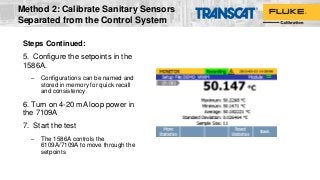
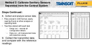
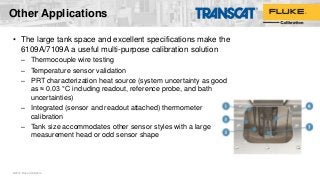
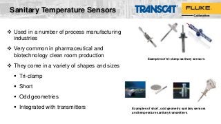
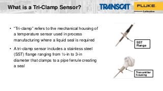
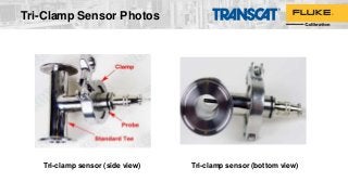
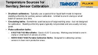
Pharmaceutical, biotechnology, and food processing companies utilize many tri-clamp and sanitary sensors in their process manufacturing. These sensors require periodic calibration which halts production. The new Fluke Calibration 6109A and 7109A Portable Calibration Baths are clean room compatible and calibrate four times more sanitary sensors per batch with twice the accuracy of other baths in their class — speeding the calibration process to get plants back on line quickly.
This webinar was presented by Michael Coleman, the Director of Temperature Metrology - Michael has been with Fluke/Hart Scientific for 18 years.
View the Fluke Calibration 6109A/7109A Series: http://www.transcat.com/fluke-calibration-6109a-7109a-portable-calibration-baths?utm_source=pardot&utm_campaign=fcal-sensor-web-6109-7109&utm_medium=email


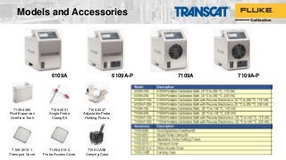
![6109A / 7109A Portable
Calibration Baths
Calibrate four tri-clamp sanitary
sensors at a time!
7109A6109A
Four times more calibration throughput
Much better accuracy than micro-baths and dry-block
calibrators
Calibrate up to four tri-clamp sanitary sensors, or a batch of sanitary
RTDs and temperature transmitters, at the same time
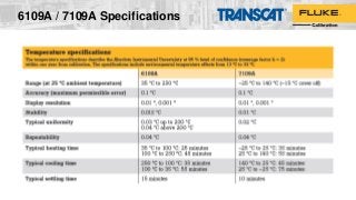
Wide temperature range covers most clean process applications:
6109A: 35 °C to 250 °C
7109A: –25 °C to 140 °C
Excellent display accuracy of ±0.1 °C
[Accuracy covers all sources of error including calibration uncertainty, stability, uniformity, and repeatability]
Perfect for clean room use -- Stainless steel panels and tank
withstand harsh sterilizing chemicals and are rust proof; Made from
materials that don’t harbor bacteria
Easy to transport up stairs and across catwalks](https://image.slidesharecdn.com/transcat-webinar-how-to-calibrate-sanitary-sensors-transcat2017-170724145551/85/Transcat-Webinar-How-to-Calibrate-Sanitary-Sensors-9-320.jpg?cb=1500908306)