Electro chemical machining - Thanuj Kumar M
•Download as PPTX, PDF•
1 like•154 views

This document provides an introduction to electro-chemical machining (ECM) processes. It discusses the basic principles of ECM including the electrolysis process that occurs. Key elements of ECM are described such as the electrolyte, tool, workpiece, and power supply. Process parameters that influence material removal rate and surface finish are outlined. Applications of ECM include machining complex shapes that would be difficult with traditional methods. Advantages include no cutting forces, high accuracy, and little tool wear.

Recommended
More Related Content
What's hot
What's hot (20)
Similar to Electro chemical machining - Thanuj Kumar M
Similar to Electro chemical machining - Thanuj Kumar M (20)
Recently uploaded
Recently uploaded (20)
Electro chemical machining - Thanuj Kumar M
- 1. Introduction to Electro-Chemical NTM Processes Prof. Thanuj Kumar M. Associate Professor, Dept. of Mech. Engg. RRCE, B’luru, Karnataka, India
- 2. 1) Introduction 2) Principle of Electro Chemical Machining: ECM Equipment, 3) Elements of ECM Operation, Chemistry of ECM. 4) ECM Process Characteristics: Material Removal Rate, Accuracy, Surface Finish. 5) Process Parameters: Current Density, Tool Feed Rate, Gap between Tool & Work Piece, Velocity of Electrolyte Flow, Type of Electrolyte, its Concentration Temperature and Choice of Electrolytes. 6) ECM Tooling: ECM Tooling Technique & examples, Tool & Insulation Materials. 7) Applications ECM: Electrochemical Grinding and Electrochemical Honing Process. 8) Advantages, Disadvantages and Application of ECG, ECH. Thanuj Kumar M., Assoc. Prof. Dept. of Mech. Engg., RRCE, Bengaluru. 02 Content: ELECTROCHEMICAL MACHINING (ECM): 10 hours
- 3. The thermal energy is applied to a very small portion of the work surface, causing that portion to be removed by fusion and/or vaporization of the material. The thermal energy is generated by conversion of electrical energy. Examples: a) ECM – Electro Chemical Machining b) EDM – Electro Discharge Machining c) LBM – Laser Beam Machining d) PBM – Plasma Beam Machining e) IBM – Ion Beam Machining Thanuj Kumar M., Assoc. Prof. Dept. of Mech. Engg., RRCE, Bengaluru. 03 Thermal Non-Traditional Machining:
- 4. Electrochemical: Mechanism is reverse of electroplating. Chemical: Most materials (metals particularly) are susceptible to chemical attack by certain acids or other etchants. In chemical machining, chemicals selectively remove material from portions of the work part, while other portions of the surface are protected by amask. Chemical milling and photochemical machining or photochemical blanking all use a chemical dissolution action to remove the machining allowance through ions in an etchant. Electrochemical machining uses the electrochemical dissolution phase to remove the machining allowance using ion transfer in an electrolytic cell. Thanuj Kumar M., Assoc. Prof. Dept. of Mech. Engg., RRCE, Bengaluru. 04 Chemical & Electro-Chemical Machining in NTM:
- 5. Non-Traditional Machining Electrochemical & Chemical Mechanical Thermal CHM USM EDM PCM WJM ECM ECM AJM LBM IJM IBM PBM Thanuj Kumar M., Assoc. Prof. Dept. of Mech. Engg., RRCE, Bengaluru. 05 Classification:
- 6. Chemical and Electrochemical Machining CHM CD Work Piece Etchant Ions ECM ECD Work Piece Electrolyte Ions PCM CD Work Piece Etchant Ions Thanuj Kumar M., Assoc. Prof. Dept. of Mech. Engg., RRCE, Bengaluru. 06
- 7. Electrochemical Machining (ECM) is one of the newest and most useful non-traditional machining (NTM) process belonging to Electrochemical category. Electrochemical machining (ECM) is used to remove metal and alloys which are difficult or impossible to machine by mechanical machining process. The reverse of electroplating. Thanuj Kumar M., Assoc. Prof. Dept. of Mech. Engg., RRCE, Bengaluru. 07 Introduction:
- 8. This machining process is based Michael Faraday’s classical laws of electrolysis, requiring basically two electrodes, an electrolyte, a gap and a source of D.C power of sufficient capacity. In a metal, electricity is conducted by free electrons but in a solution the conduction of electricity is achieved through the movement of ions. Thus the flow of current through an electrolyte is always accompanied by the movement of matter. In the ECM process the work-piece is connected to a positive (+ve) electrode and the tool to the negative (-ve) terminal for metal removal. Thanuj Kumar M., Assoc. Prof. Dept. of Mech. Engg., RRCE, Bengaluru. 08
- 9. The first introduction of ECM was in 1929 by Gusseff, Its industrial applications have been extended to electro- chemical drilling, electro-chemical deburring, electro- chemical grinding and electro-chemical polishing . Its machining technique was started in late 60’s & 70’s. Thanuj Kumar M., Assoc. Prof. Dept. of Mech. Engg., RRCE, Bengaluru. 09 History:
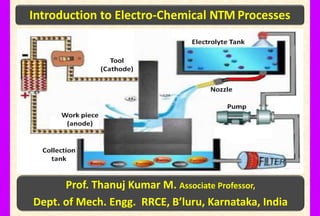
- 10. Thanuj Kumar M., Assoc. Prof. Dept. of Mech. Engg., RRCE, Bengaluru. 010 Schematic Diagram of Electro-Chemical Machining (ECM)
- 11. Machining processes Complex parts machined Thanuj Kumar M., Assoc. Prof. Dept. of Mech. Engg., RRCE, Bengaluru. 011 Electro Chemical Machine and Machined Parts
- 12. Thanuj Kumar M., Assoc. Prof. Dept. of Mech. Engg., RRCE, Bengaluru. 012 Gif file Showing How Electro Chemical Machining Works
- 13. Thanuj Kumar M., Assoc. Prof. Dept. of Mech. Engg., RRCE, Bengaluru. 013 Steps for Electro Chemical Machining Works Step-6 Step-5 Step-7 Step-4 Step-2 Step-1 Step-3
- 14. Important Elements of ECM are: 1. Electrolyte 2. Tool (Cathode) 3. Work-Piece (Anode) 4. D.C Power Supply Thanuj Kumar M., Assoc. Prof. Dept. of Mech. Engg., RRCE, Bengaluru. 014 Elements of ECM Machine:
- 15. Common electrolytes used are sodium chloride, sodium nitrate, sodium hydroxide, sodium fluoride, sodium chlorate, potassium chloride and sulphuric acid. These solution on reaction produce an insoluble compound in the form of sludge. The main functions of an electrolyte in ECM are: 1. It carries the current between tool and work-piece. 2. It removes the products ofmachining and other insoluble products from the cutting region. 3. It dissipates heat produced in the operation. Thanuj Kumar M., Assoc. Prof. Dept. of Mech. Engg., RRCE, Bengaluru. 015 Electrolyte:
- 16. In the electrolytic circuit the electron is flow from the work-piece through the power supply to the tool. The electrolysis process that takes place at the cathode liberates hydroxyl ions(OH-) and free hydrogen. The hydroxyl ions combine with the metal ions of the anode to form insoluble metal hydroxides and material is thus removed from the anode. At cathode, the following reactions takes place: 2H++ 2e- H2 (Hydrogen evolution) M++ e- M (M denotes metal) Thanuj Kumar M., Assoc. Prof. Dept. of Mech. Engg., RRCE, Bengaluru. 016 Electrolysis Process:
- 17. At anode, the following reactions takes place with a halogen electrolyte M M++ e-(Metal dissolution) 2H2O 2Cl- O2+ 4H++ 4e- (Oxygen evolution) Cl2+ 2e- (Halogen gas evolution) As an example, in machining of iron in NaCl electrolyte, at the cathode the reaction products are FeCl2, Fe(OH)2, Fe(OH)3 which forms a layer and this is how iron is removed by electrolytic action. Current of 1000 A would dissolve iron at the rate of about 15g/min and generate hydrogen at a rate of about 300cm3/min. Thanuj Kumar M., Assoc. Prof. Dept. of Mech. Engg., RRCE, Bengaluru. 017
- 18. The most commonly used tool material are copper, brass, titanium, copper tungsten and stainless steels when electrolyte is made of salts of sodium and potassium. Titanium has been found to be the most suitable tool where the electrolyte has the tendency to anodize the tool as in case of sulphuric acid. The other tool materials are aluminium, graphite, bronze, platinum and tungsten carbide. The accuracy of tool shape directly affects the work- piece accuracy. Electro-forming and cold forging are two methods used for tool shaping. Thanuj Kumar M., Assoc. Prof. Dept. of Mech. Engg., RRCE, Bengaluru. 018 Tool (Cathode):
- 19. 1) It should be conductor of electricity. 2) It should be rigid enough to take up the load due to fluid pressure. 3) It should be chemically inert to the electrolyte. 4) It should be easily machinable to make it in the desired shape. 1) Work-piece should be conductor of electricity. So it is almost limited to metals only. Thanuj Kumar M., Assoc. Prof. Dept. of Mech. Engg., RRCE, Bengaluru. 019 General requirements of tool material: Work-Piece (Anode):
- 20. Current type : DC Voltage : 2 to 35 V Current : 50 to 40,000A Current density : 0.1 A/mm2 to 5A/mm2 Material : NaCl and NaNO3 Temperature : 20oC – 50oC Flow rate : 20 lpm per 100 Acurrent Pressure : 0.5 to 20bar Dilution : 100 g/l to 500 g/l Working gap : 1mm to 2mm Overcut : 2mm to 3mm Feed rate : 0.5mm/min to 15mm/min Electrode material : Copper, Brass, Bronze Surface roughness : Ra 0.2 to 1.5 μm Thanuj Kumar M., Assoc. Prof. Dept. of Mech. Engg., RRCE, Bengaluru. 020 Power Supply: Electrolyte:
- 21. In this process of ECM, the tool (mirror image of work-piece) is the cathode and work-piece is the anode. A gap (0.05 to 0.7 mm) is provided between the tool & work-piece so that electrolyte flows through the gap at a velocity of 30 to 60 m/s, thus completes the electrical circuit. Electrolyte is pumped at high pressure of 20kgf/cm2(1.96 MPa) through the gap. Electrolyte must be circulated at a rate sufficiently high to conduct current between them and to carry heat. Thanuj Kumar M., Assoc. Prof. Dept. of Mech. Engg., RRCE, Bengaluru. 021 Working of ECM:
- 22. Metal is removed from the work-piece by dissolution. The electric current is of the order of 50 to 40,000A at 5 to 35V (DC) for current density of 20 to 300A/cm2. Power of 3KWh is needed to remove 16cm3 of metal which is almost 30times the energy required in the conventional process (when the material is readily machinable). Thanuj Kumar M., Assoc. Prof. Dept. of Mech. Engg., RRCE, Bengaluru. 022
- 23. Material Removal Rate: MRR depends mainly on feed rates. The feed rate determines the current passed between the work & the tool. As the tool approaches the work, the length of the conductive current path decreases & the magnitude of current increases. This continues until the current is just sufficient to remove the metal at a rate corresponding to the rate of tool advance. A stable cut is then made with a fixed spacing between the work and the tool, termed as the equilibrium-machining gap. If the tool feed rate is reduced, the tool advance will momentarily lag behind, increasing the gap and thus resulting in a reduction of current. This happens until a stable gap is once again established. Thanuj Kumar M., Assoc. Prof. Dept. of Mech. Engg., RRCE, Bengaluru. 023 ECM Process Characteristics:
- 24. Under ideal conditions & with properly designed tooling, ECM is capable of holding tolerance of the order of 0.02 mm & less. Repeatability of the ECM process is also very good. This is largely due to the fact that the tool wear is virtually non-existent on a good machine; tolerance can be maintained on a production basis in the region of 0.02 - 0.04 mm. As a general rule, the more complex the shape of the work, the more difficult is to hold tight tolerances and the greater is the attention required for developing a proper tooling and electrode shape. Thanuj Kumar M., Assoc. Prof. Dept. of Mech. Engg., RRCE, Bengaluru. 024 Accuracy:
- 25. ECM under certain conditions can produce surface finishes of the order of 0.4µm. This can be obtained by the frontal cut or the rotation of the tool or the work. The important variables affecting the surface finish are feed rate, gap dimension, electrolyte composition, viscosity, temperature & flow. Any defect on the tool will cause machining defects on the surface of the work. Thanuj Kumar M., Assoc. Prof. Dept. of Mech. Engg., RRCE, Bengaluru. 025 Surface Finish:
- 26. Feed Rate: A high feed rate results in higher metal removal rate. It decreases the equilibrium machining gap resulting in improvement of surface finish and tolerance control. Voltage: Low voltage decreases the equilibrium-machining gap and results in better surface finish and tolerance control. Nature of Power Supply and Machining Pulse: The nature of applied power supply may be of two types, such as DC (full wave rectified) and pulse DC. A full wave rectified DC supplies continuous voltage where the current efficiency depends much more on the current density. The efficiency decreases gradually when the current density is reduced, whereas in pulse voltage (duration of 1 ms and interval of 10 ms) the decrease is much more rapid. With decreasing current density the accuracy of the form of the work-piece improves. Thanuj Kumar M., Assoc. Prof. Dept. of Mech. Engg., RRCE, Bengaluru. 026 Operating Parameters:
- 27. a) Passivity Electrolyte: containing oxidizing anions e.g. sodium nitrate and sodium chlorate, etc. Passivity electrolytes are known to give better machining precision due to their ability to form oxide films and evolve oxygen in the stray current region. b) Non-Passivity Electrolyte: containing relatively aggressive anions such as sodium chloride. Note: NaClO3, NaNO3, and NaCl solution with different concentration are used for electrochemical machining (ECM). The pH value of the electrolyte solution is chosen to 15 ensure good dissolution of the work-piece material during the ECM process without the tool being attacked. Thanuj Kumar M., Assoc. Prof. Dept. of Mech. Engg., RRCE, Bengaluru. 027 Electrolyte Type, Concentration and Flow:
- 28. The tool must match the required shape of the workpiece depending on the material and the profile to be produced. Tool materials used in ECM must have good thermal and electrical conductivity, corrosion resistance must be highly machinable and should be stiff enough to withstand the electrolytic pressure without vibrating. Thanuj Kumar M., Assoc. Prof. Dept. of Mech. Engg., RRCE, Bengaluru. 028 Size, Shape and Material of the Tool:
- 29. MRR vs. Tool Feed Rate From the graph it shows that the MRR is influenced by feed rate. The material removal rate increases with feed rate because the machining time decreases. MRR vs. Tool Feed Rate From the graph it shows that the MRR is also influenced by voltage change but moderately. Conclusion: MRR increases with the Tool Feed Rate as well as the Voltage, but it depends mainly on the tool feed rate. Thanuj Kumar M., Assoc. Prof. Dept. of Mech. Engg., RRCE, Bengaluru. 029 Process Parameters:
- 30. Advantages: 1. There is no cutting forces therefore clamping is not required except for controlled motion of the work piece. 2. It can machine configurations which is beyond the capability of conventional machining processes. 3. Very accurate (tolerance of ±0.02 mm). 4. Relatively fast. 5. Can machine harder metals than the tool. 6. Extremely thin material scan be easily worked without 7. Distortion 8. Tool wear is nearly absent. 9. Better surface finish (0.2 to 0.8 micron). Thanuj Kumar M., Assoc. Prof. Dept. of Mech. Engg., RRCE, Bengaluru. 030
- 31. High energy consumption. Non conducting material cannot be machined. Corrosion and rust of ECM machine can be hazardous but preventive measures can help in this regard. Thanuj Kumar M., Assoc. Prof. Dept. of Mech. Engg., RRCE, Bengaluru. 031 Disadvantages:
- 32. The most common application of ECM is high accuracy duplication. Because there is no tool wear, it can be used repeatedly with a high degree of accuracy. It is commonly used on thin walled, easily deformable and brittle material because they would probably develop cracks with conventional machining. It is used in machining of hard-heat-resisting alloys. It is used in cutting cavities and holes in various products, machining of complex external shapes like that of turbine blades, aerospace components and machining of tungsten carbide and nozzles of alloy steels. Used for copying of internal and external surfaces, cutting of curvilinear slots, machining of intricate patterns, production of long curved profiles, machining of gears & chain sprockets, production of integrally bladed nozzle for use in diesel locomotives, production of satellite rings and connecting rods, machining of thin large diameter diaphragms. Also used for slotting very thin walled collets. Thanuj Kumar M., Assoc. Prof. Dept. of Mech. Engg., RRCE, Bengaluru. 032 Applications: