Download to read offline


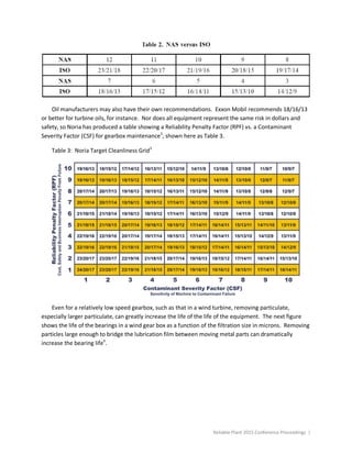


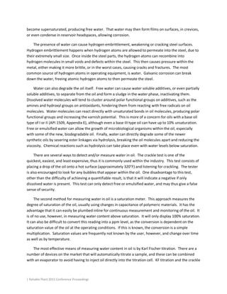
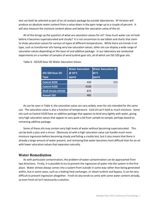
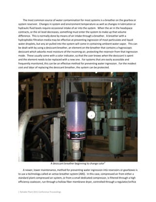

This document summarizes different forms of lubricant contamination and methods for remediation. It discusses three primary forms of contamination: particulate, water, and gases. Particulate contamination consists of solid particles in the fluid and can be measured by particle counts. Filtration is an important method for removing particulate contamination. Water contamination can take various forms and can cause corrosion, wear, and hydrogen embrittlement. The document also discusses addressing contamination sources and various filtration and remediation methods.


![DESIGN AND FABRICATION OF THE IBM 90-90 SEAT BELT CLAMP KIA VEHICLE[1].pptx 2...](https://cdn.slidesharecdn.com/ss_thumbnails/designandfabricationoftheibm90-90seatbeltclampkiavehicle1-260116160442-70ff67fc-thumbnail.jpg?width=640&height=640&fit=bounds)


