SlideShare a Scribd company logo
1 of 10
Download to read offline
MEMO 55b
www.invisibleconnections.noPage 1 of 10
REKOMMENDED REINFORCEMENT
PATTERN RVK 101
Figure 1: Recommended reinforcement pattern for RVK 101 units. Slab thickness t=265mm and edge
distance k>450mm. Slab thickness t=200mm and edge distance k>400mm.
MEMO 55b
RVK 101
REKOMMENDED REINFORCEMENT
PATTERN
DESIGN
Dato:
Siste rev.:
Dok. nr.:
Sign.:
Sign.:
Control:
26.04.2011
25.05.2016
K3-10/55bE
sss
sss
ps
MEMO 55b
www.invisibleconnections.noPage 2 of 10
Figure 2: Recommended reinforcement pattern for RVK 101 units. Slab thickness t=265mm and edge
distance 180mm≤k≤450mm. Slab thickness t=200mm and edge distance 180mm≤k≤400mm. Ultimate
limit load according to Figure 5.
MEMO 55b
www.invisibleconnections.noPage 3 of 10
Figure 3: Recommended reinforcement pattern for RVK 101 units. Slab thickness t<265mm and edge
distance 180mm≤k<300mm. Ultimate limit load according to Figure 5.
MEMO 55b
www.invisibleconnections.noPage 4 of 10
The following comments can be made in connection with the recommended reinforcement pattern
shown in Figure 1:
• Reinforcement is illustrated in a slab with thickness 265mm, concrete cover 30mm and large edge
distance.
• In the area marked “c/c*)”, the tested elements (thickness t=265mm) were reinforced with P9 c/c
150mm along the whole edge.
• Two stirrups P9 to be placed closed to the unit. One on each side. Edge reinforcement P9 beyond the
prescribed locations should be in accordance with calculations. However, according to EC 2 clauses
6.4.2(5) and 9.3.1.4, stirrups continuously along the edge are always recommended.
• Transverse reinforcement P5 in the bends of P9. When the concrete cover is 25mm, or less, the upper
P5 bar can run above the half round steel in front of the unit. With 30mm concrete cover, the upper P5
bar may have to be cut. Then, a straight bar P8 is to be placed transverse of the unit as illustrated, in
overlap with P5. If possible, the P5 bar should be made continuously.
• The illustrated reinforcement is the necessary reinforcement required to transfer the forces in the unit
to the concrete. It is not to be understood as the complete slab reinforcement. The main reinforcement
for the slab/landings, inclusive edge reinforcement must be calculated in each case.
The following comments can be made in connection with the recommended reinforcement pattern
shown in Figure 2:
• Reinforcement is illustrated in a slab with thickness 265mm, concrete cover 30mm and edge distance
180mm.
• In the areas marked “c/c*)”, the tested elements (thickness t=265mm) were reinforced with P10 c/c
150mm and P9 c/c 150mm along the two edges.
• Mesh reinforcement with transverse reinforcement P10 (closed bars) below. P10 runs above the unit,
and below P1/P2. The mesh reinforcement may be replaced with straight bars with corresponding
cross section area and c/c distance.
• Slab thickness t=200mm: When the unit is located at 400mm, or closer to the corner than 400mm,
stirrups shall always be used along both edges as prescribed (P9/P10).
Slab thickness t=265mm: When the unit is located at 450mm, or closer to the corner than 450mm,
stirrups shall always be used along both edges as prescribed (P9/P10).
These stirrups anchor the main reinforcement, and will in addition function as shear reinforcement in
the slab. Edge reinforcement P9/P10 beyond the prescribed locations should be in accordance with
calculations. However, according to EC 2 clauses 6.4.2(5) and 9.3.1.4, stirrups continuously along the
edge are always recommended.
• P10 may be replaced with u-shaped stirrups in overlap with straight bars.
MEMO 55b
www.invisibleconnections.noPage 5 of 10
• The illustrated reinforcement is to be understood as a minimum of reinforcement which always should
be found when the unit is located close to the corner. It is not to be understood as the complete slab
reinforcement. The main reinforcement for the slab/landings, inclusive edge reinforcement must be
calculated in each case.
The following comments can be made in connection with the recommended reinforcement pattern
shown in Figure 3:
• Reinforcement is illustrated in a slab with thickness 200mm, concrete cover 30mm and edge distance
180mm. Notice the reduction in load in this case, see Figure 5.
• In the areas marked “c/c*)”, the tested elements (thickness t=200mm) were reinforced with P10 c/c
150mm and P9 c/c 100mm along the two edges.
• Mesh reinforcement with transverse reinforcement P10 (closed bars) below. P10 runs above the unit,
and below P1/P2. The mesh reinforcement may be replaced with straight bars with corresponding
cross section area and c/c distance.
• Slab thickness t=200mm: When the unit is located at 400mm, or closer to the corner than 400mm,
stirrups shall always be used along both edges as prescribed (P9/P10).
Slab thickness t=265mm: When the unit is located at 450mm, or closer to the corner than 450mm,
stirrups shall always be used along both edges as prescribed (P9/P10).
These stirrups anchor the main reinforcement, and will in addition function as shear reinforcement in
the slab. Edge reinforcement P9/P10 beyond the prescribed locations should be in accordance with
calculations. However, according to EC 2 clauses 6.4.2(5) and 9.3.1.4, stirrups continuously along the
edge are always recommended.
• When the slab thickness is less than 265mm, and the unit is located closer to the corner than 300mm,
stirrups P13 (shear reinforcement) may be used in the corner area, as illustrated, to increase the
concrete capacity, see Figure 5.
• P10 may be replaced with u-shaped stirrups in overlap with straight bars.
• Transverse reinforcement 4Ø12 –P5 behind the unit as illustrated.
• The illustrated reinforcement is to be understood as a minimum of reinforcement which always should
be found when the unit is located close to the corner. However, is not to be understood as the complete
slab reinforcement. The main reinforcement for the slab/landings, inclusive edge reinforcement must
be calculated in each case.
MEMO 55b
www.invisibleconnections.noPage 6 of 10
General comments in connection with all reinforcement patterns:
• Minimum slab thickness: t=200mm. Notice the reduction in load, see Figure 5.
• P1 and P2 to be placed directly onto the unit, with the half round steel at top of the unit positioned in
the bend of P1/P2. It is recommended to spot weld P1 and P2 to the unit in order to ensure the correct
position.
• Position, shape and anchorage of the stirrups P1 and P2 in the front is the governing factor concerning
force transfer from the unit to the slab. Exact and careful detailing is therefore important. Inaccuracy
may cause minor concrete cracks to develop before activating the reinforcement as assumed.
• Transverse reinforcement in the bend of P1/P2 (P5). P5 shall have the same diameter as P1/P2 and
should run along the whole width of the slab.
• The transverse reinforcement P5 may be a part of the main transverse reinforcement and should have
proper anchoring on the outside of the unit on both sides, especially towards the edge. This may
require anchoring of P5 with an upward bend, or u-shaped bars. The required anchoring must be
evaluated in every case.
• P1 and P2 should be anchored to the maximum depth, depending on the slab thickness.
• The inner width of the stirrups P1 and P2 should correspond to the width of the outer tube. This in
order to have the most direct transfer of forces from the outer tube to the vertical legs of the stirrups.
• The main reinforcement of the slab should have sufficient overlap with P1 and P2. This is illustrated
with four straight bars P12. The total amount of main reinforcement must be calculated in each case.
• All recommended reinforcement assumed to continue beyond the boundary of the illustrated area shall
have a proper anchoring on the outside of the area. Thus, the reinforcement should continue at least
one anchoring length outside the illustrated area, or be anchored by hooks.
• Shear reinforcement due to punching shear according to EC 2, clause 6.4.3.
MEMO 55b
www.invisibleconnections.noPage 7 of 10
Tolerances on location of anchoring bars:
Figure 4: Tolerances P1, P2 and P4.
Figure 5: Slab thickness, recommended reinforcement pattern and load limitations. The coloured arrows
refer to the recommended reinforcement patterns, as given in above Figures. The colour of the arrow
giving the recommended reinforcement pattern corresponds to the colour of the line giving the load
limitation. (In Memo 52, Figure 3, the load limitation is illustrated alone, without the arrows and
references to reinforcement pattern)
MEMO 55b
www.invisibleconnections.noPage 8 of 10
Pos Diameter Cutting
length
Nr. Pr
unit
Bar schedule Grade 3)
P1 12 1
Mandrel diameter=32mm (if this is in accordance with
national regulations.)
h=Decided locally, but as deep as possible. Normally: Slab
thickness - 40mm - national rules for concrete cover.
If the mandrel diameter is 4xØ (in accordance with EC-2) the
width should be increased to 130mm to ensure good
contact between the stirrups and the round steel.
500C
(EC2,
App C)
P2 12 1
Mandrel diameter=32mm (if this is in accordance with
national regulations.)
h=Decided locally, but as deep as possible. Normally: Slab
thickness - 40mm - national rules for concrete cover.
If the mandrel diameter is 4xØ (in accordance with EC-2) the
widths should be increased to respectively 130mm and 160
mm to ensure good contact between the stirrups and the
round steel.
500C
(EC2,
App C)
P4 12 2
h= Decided locally. Normally: Slab thickness – 30mm – 2 x
national rules for concrete cover.
500C
(EC2,
App C)
P5 12 2
62)
Normally: Width of slab – 2 x national rules for concrete
cover.
500C
(EC2,
App C)
P6 12 1000 2 500C
(EC2,
App C)
P7 12 1000 2
Slab thickness t=200mm: There is not enough space for the
bars, and they don’t need to be used.
500C
(EC2,
App C)
MEMO 55b
www.invisibleconnections.noPage 9 of 10
Pos Diameter Cutting
length
Nr. Pr
unit
Bar schedule Grade 3)
P8 12 1
Normally: Width of slab – 2 x national rules for concrete
cover. Alternatively u-shaped or closed stirrups may be
used.
500C
(EC2,
App C)
P9 10 2 +
31)
+
62)
+
h= Decided locally. Normally: Slab thickness –30mm – 2 x
national rules for concrete cover. Recommended along
whole edge.
500C
(EC2,
App C)
P10 12 31), 2)
+
h= Decided locally. Normally: Slab thickness – 2 x national
rules for concrete cover – thickness of mesh reinforcement.
500C
(EC2,
App C)
P11 Minimum mesh reinforcement K131, or main reinforcement
in both directions with corresponding cross section area and
c/c.
500C
(EC2,
App C)
P12 12 4 +
51), 2)
+
The amount of main reinforcement must be according to
calculations in each case.
Minimum 4xØ12 in overlap with P1/P2 as illustrated.
Normally: Length of slab – 2 x national rules for concrete
cover
500C
(EC2,
App C)
P13 8 142)
h= Decided locally. Normally: Slab thickness – 2 x national
rules for concrete cover – thickness of mesh reinforcement.
500C
(EC2,
App C)
1)
Edge distance≤400mm. Slab thickness, t=200mm.
Edge distance≤450mm. Slab thickness, t=265mm.
2)
Edge distance<300mm and slab thickness t<265mm.
3)
Reinforcement steel of different ductility grade may be chosen provided that the bendability is sufficient for fitting
the vertical suspension reinforcement to the half round steels in front of the unit.
Table 1: List of reinforcement RVK 101.
MEMO 55b
www.invisibleconnections.noPage 10 of 10
REVISION HISTORY
Date: Description:
26.04.2011 First Edition.
04.07.2011 Updated.
07.01.2016 Included revision history table. Included note on reinforcement ductility grade in Table 1.
25.05.2016 New template

More Related Content

What's hot

Rcc slab design guidelines
Rcc slab design guidelinesRcc slab design guidelines
Rcc slab design guidelinesMain Uddin
 
Design of column base plates anchor bolt
Design of column base plates anchor boltDesign of column base plates anchor bolt
Design of column base plates anchor boltKhaled Eid
 
Anchor bolt design
Anchor bolt designAnchor bolt design
Anchor bolt designVaradaraj Ck
 
Economical placement of shear walls in a moment resisting frame for earthquak...
Economical placement of shear walls in a moment resisting frame for earthquak...Economical placement of shear walls in a moment resisting frame for earthquak...
Economical placement of shear walls in a moment resisting frame for earthquak...eSAT Publishing House
 
Beams design and analysis
Beams design and analysisBeams design and analysis
Beams design and analysisAman Adam
 
Koppolu abishek prying action
Koppolu abishek   prying actionKoppolu abishek   prying action
Koppolu abishek prying actionKoppolu Abishek
 
Design of tension members
Design of tension membersDesign of tension members
Design of tension membersSabna Thilakan
 
Slabs Beam Reinforcement Detailing
Slabs Beam Reinforcement DetailingSlabs Beam Reinforcement Detailing
Slabs Beam Reinforcement DetailingMake Mannan
 
Hollow block and ribbed slabs
Hollow block and ribbed slabsHollow block and ribbed slabs
Hollow block and ribbed slabsMohamed Mohsen
 
Connection design
Connection designConnection design
Connection designEduardo
 
Connections in steel structures
Connections in steel structuresConnections in steel structures
Connections in steel structuresanand bhatnagar
 
Punching Shears 1.1
Punching Shears 1.1Punching Shears 1.1
Punching Shears 1.1Milan Stanic
 
Lec05 Design of Rectangular Beams with Tension Steel only (Reinforced Concret...
Lec05 Design of Rectangular Beams with Tension Steel only (Reinforced Concret...Lec05 Design of Rectangular Beams with Tension Steel only (Reinforced Concret...
Lec05 Design of Rectangular Beams with Tension Steel only (Reinforced Concret...Hossam Shafiq II
 

What's hot (20)

Details of REINFORCEMENT Summary
Details of REINFORCEMENT SummaryDetails of REINFORCEMENT Summary
Details of REINFORCEMENT Summary
 
Beam design
Beam designBeam design
Beam design
 
Rcc slab design guidelines
Rcc slab design guidelinesRcc slab design guidelines
Rcc slab design guidelines
 
Design of column base plates anchor bolt
Design of column base plates anchor boltDesign of column base plates anchor bolt
Design of column base plates anchor bolt
 
Anchor bolt design
Anchor bolt designAnchor bolt design
Anchor bolt design
 
DESIGN OF FLAT SLABS
DESIGN OF FLAT SLABSDESIGN OF FLAT SLABS
DESIGN OF FLAT SLABS
 
Economical placement of shear walls in a moment resisting frame for earthquak...
Economical placement of shear walls in a moment resisting frame for earthquak...Economical placement of shear walls in a moment resisting frame for earthquak...
Economical placement of shear walls in a moment resisting frame for earthquak...
 
Beams design and analysis
Beams design and analysisBeams design and analysis
Beams design and analysis
 
Koppolu abishek prying action
Koppolu abishek   prying actionKoppolu abishek   prying action
Koppolu abishek prying action
 
CLUSTER POROSITY
CLUSTER POROSITYCLUSTER POROSITY
CLUSTER POROSITY
 
Design of tension members
Design of tension membersDesign of tension members
Design of tension members
 
Design of pile cap
Design of pile capDesign of pile cap
Design of pile cap
 
Slabs Beam Reinforcement Detailing
Slabs Beam Reinforcement DetailingSlabs Beam Reinforcement Detailing
Slabs Beam Reinforcement Detailing
 
Hollow block and ribbed slabs
Hollow block and ribbed slabsHollow block and ribbed slabs
Hollow block and ribbed slabs
 
Connection design
Connection designConnection design
Connection design
 
Connections in steel structures
Connections in steel structuresConnections in steel structures
Connections in steel structures
 
Swimming pool new roof
Swimming pool new roofSwimming pool new roof
Swimming pool new roof
 
Clamp or compression coupling
Clamp or compression couplingClamp or compression coupling
Clamp or compression coupling
 
Punching Shears 1.1
Punching Shears 1.1Punching Shears 1.1
Punching Shears 1.1
 
Lec05 Design of Rectangular Beams with Tension Steel only (Reinforced Concret...
Lec05 Design of Rectangular Beams with Tension Steel only (Reinforced Concret...Lec05 Design of Rectangular Beams with Tension Steel only (Reinforced Concret...
Lec05 Design of Rectangular Beams with Tension Steel only (Reinforced Concret...
 

Similar to Memo 55b-rvk-101-rekommended-reinforcement-pattern

Two pile group
Two pile groupTwo pile group
Two pile groupNaOzas
 
Instruction- 3 Core Polymeric (XLPE EPR) 6.6kV-7.2kV Heat Shrink Cable Termin...
Instruction- 3 Core Polymeric (XLPE EPR) 6.6kV-7.2kV Heat Shrink Cable Termin...Instruction- 3 Core Polymeric (XLPE EPR) 6.6kV-7.2kV Heat Shrink Cable Termin...
Instruction- 3 Core Polymeric (XLPE EPR) 6.6kV-7.2kV Heat Shrink Cable Termin...Thorne & Derrick International
 
Design of Beam- RCC Singly Reinforced Beam
Design of Beam- RCC Singly Reinforced BeamDesign of Beam- RCC Singly Reinforced Beam
Design of Beam- RCC Singly Reinforced BeamSHAZEBALIKHAN1
 
Concrete flexural design
Concrete flexural designConcrete flexural design
Concrete flexural designWaqas Javaid
 
Compression member
Compression memberCompression member
Compression memberVikas Mehta
 
Theory for Welded connection.pdf
Theory for Welded connection.pdfTheory for Welded connection.pdf
Theory for Welded connection.pdfYatiTank
 
DESIGN OF RIVETED JOINTS.pptx
DESIGN OF RIVETED JOINTS.pptxDESIGN OF RIVETED JOINTS.pptx
DESIGN OF RIVETED JOINTS.pptxPraveenK19954
 
Lec12 Continuous Beams and One Way Slabs(2) Columns (Reinforced Concrete Desi...
Lec12 Continuous Beams and One Way Slabs(2) Columns (Reinforced Concrete Desi...Lec12 Continuous Beams and One Way Slabs(2) Columns (Reinforced Concrete Desi...
Lec12 Continuous Beams and One Way Slabs(2) Columns (Reinforced Concrete Desi...Hossam Shafiq II
 
07-Ductile-detailing-RC-Buildings.pdf
07-Ductile-detailing-RC-Buildings.pdf07-Ductile-detailing-RC-Buildings.pdf
07-Ductile-detailing-RC-Buildings.pdfkksingh1010195
 
Design of Main Girder [Compatibility Mode].pdf
Design of Main Girder [Compatibility Mode].pdfDesign of Main Girder [Compatibility Mode].pdf
Design of Main Girder [Compatibility Mode].pdfmohamed abdo
 
Design of torsion reinforcement
 Design of torsion reinforcement Design of torsion reinforcement
Design of torsion reinforcementMuskanDeura
 
Esd ppt 150180106093,111,160183106008 GECDAHOD
Esd ppt 150180106093,111,160183106008 GECDAHODEsd ppt 150180106093,111,160183106008 GECDAHOD
Esd ppt 150180106093,111,160183106008 GECDAHODyasir Khan
 
Connection_Design.ppt
Connection_Design.pptConnection_Design.ppt
Connection_Design.pptkasarla sagar
 
Connection_Design.ppt
Connection_Design.pptConnection_Design.ppt
Connection_Design.pptssuser474b33
 

Similar to Memo 55b-rvk-101-rekommended-reinforcement-pattern (20)

Two Pile Group.pdf
Two Pile Group.pdfTwo Pile Group.pdf
Two Pile Group.pdf
 
Two Pile Group.pdf
Two Pile Group.pdfTwo Pile Group.pdf
Two Pile Group.pdf
 
Two pile group
Two pile groupTwo pile group
Two pile group
 
pile group
pile grouppile group
pile group
 
Instruction- 3 Core Polymeric (XLPE EPR) 6.6kV-7.2kV Heat Shrink Cable Termin...
Instruction- 3 Core Polymeric (XLPE EPR) 6.6kV-7.2kV Heat Shrink Cable Termin...Instruction- 3 Core Polymeric (XLPE EPR) 6.6kV-7.2kV Heat Shrink Cable Termin...
Instruction- 3 Core Polymeric (XLPE EPR) 6.6kV-7.2kV Heat Shrink Cable Termin...
 
Design of Beam- RCC Singly Reinforced Beam
Design of Beam- RCC Singly Reinforced BeamDesign of Beam- RCC Singly Reinforced Beam
Design of Beam- RCC Singly Reinforced Beam
 
Concrete flexural design
Concrete flexural designConcrete flexural design
Concrete flexural design
 
Compression member
Compression memberCompression member
Compression member
 
Theory for Welded connection.pdf
Theory for Welded connection.pdfTheory for Welded connection.pdf
Theory for Welded connection.pdf
 
DESIGN OF RIVETED JOINTS.pptx
DESIGN OF RIVETED JOINTS.pptxDESIGN OF RIVETED JOINTS.pptx
DESIGN OF RIVETED JOINTS.pptx
 
Lec12 Continuous Beams and One Way Slabs(2) Columns (Reinforced Concrete Desi...
Lec12 Continuous Beams and One Way Slabs(2) Columns (Reinforced Concrete Desi...Lec12 Continuous Beams and One Way Slabs(2) Columns (Reinforced Concrete Desi...
Lec12 Continuous Beams and One Way Slabs(2) Columns (Reinforced Concrete Desi...
 
0 ne way slab
0 ne way slab0 ne way slab
0 ne way slab
 
07-Ductile-detailing-RC-Buildings.pdf
07-Ductile-detailing-RC-Buildings.pdf07-Ductile-detailing-RC-Buildings.pdf
07-Ductile-detailing-RC-Buildings.pdf
 
Design of Main Girder [Compatibility Mode].pdf
Design of Main Girder [Compatibility Mode].pdfDesign of Main Girder [Compatibility Mode].pdf
Design of Main Girder [Compatibility Mode].pdf
 
Steel column base44
Steel column base44Steel column base44
Steel column base44
 
Design of torsion reinforcement
 Design of torsion reinforcement Design of torsion reinforcement
Design of torsion reinforcement
 
Ductile detailing
Ductile detailingDuctile detailing
Ductile detailing
 
Esd ppt 150180106093,111,160183106008 GECDAHOD
Esd ppt 150180106093,111,160183106008 GECDAHODEsd ppt 150180106093,111,160183106008 GECDAHOD
Esd ppt 150180106093,111,160183106008 GECDAHOD
 
Connection_Design.ppt
Connection_Design.pptConnection_Design.ppt
Connection_Design.ppt
 
Connection_Design.ppt
Connection_Design.pptConnection_Design.ppt
Connection_Design.ppt
 

Recently uploaded

"I see eyes in my soup": How Delivery Hero implemented the safety system for ...
"I see eyes in my soup": How Delivery Hero implemented the safety system for ..."I see eyes in my soup": How Delivery Hero implemented the safety system for ...
"I see eyes in my soup": How Delivery Hero implemented the safety system for ...Zilliz
 
[BuildWithAI] Introduction to Gemini.pdf
[BuildWithAI] Introduction to Gemini.pdf[BuildWithAI] Introduction to Gemini.pdf
[BuildWithAI] Introduction to Gemini.pdfSandro Moreira
 
Corporate and higher education May webinar.pptx
Corporate and higher education May webinar.pptxCorporate and higher education May webinar.pptx
Corporate and higher education May webinar.pptxRustici Software
 
Polkadot JAM Slides - Token2049 - By Dr. Gavin Wood
Polkadot JAM Slides - Token2049 - By Dr. Gavin WoodPolkadot JAM Slides - Token2049 - By Dr. Gavin Wood
Polkadot JAM Slides - Token2049 - By Dr. Gavin WoodJuan lago vázquez
 
Modular Monolith - a Practical Alternative to Microservices @ Devoxx UK 2024
Modular Monolith - a Practical Alternative to Microservices @ Devoxx UK 2024Modular Monolith - a Practical Alternative to Microservices @ Devoxx UK 2024
Modular Monolith - a Practical Alternative to Microservices @ Devoxx UK 2024Victor Rentea
 
Apidays New York 2024 - The Good, the Bad and the Governed by David O'Neill, ...
Apidays New York 2024 - The Good, the Bad and the Governed by David O'Neill, ...Apidays New York 2024 - The Good, the Bad and the Governed by David O'Neill, ...
Apidays New York 2024 - The Good, the Bad and the Governed by David O'Neill, ...apidays
 
Rising Above_ Dubai Floods and the Fortitude of Dubai International Airport.pdf
Rising Above_ Dubai Floods and the Fortitude of Dubai International Airport.pdfRising Above_ Dubai Floods and the Fortitude of Dubai International Airport.pdf
Rising Above_ Dubai Floods and the Fortitude of Dubai International Airport.pdfOrbitshub
 
Architecting Cloud Native Applications
Architecting Cloud Native ApplicationsArchitecting Cloud Native Applications
Architecting Cloud Native ApplicationsWSO2
 
Web Form Automation for Bonterra Impact Management (fka Social Solutions Apri...
Web Form Automation for Bonterra Impact Management (fka Social Solutions Apri...Web Form Automation for Bonterra Impact Management (fka Social Solutions Apri...
Web Form Automation for Bonterra Impact Management (fka Social Solutions Apri...Jeffrey Haguewood
 
Exploring Multimodal Embeddings with Milvus
Exploring Multimodal Embeddings with MilvusExploring Multimodal Embeddings with Milvus
Exploring Multimodal Embeddings with MilvusZilliz
 
Repurposing LNG terminals for Hydrogen Ammonia: Feasibility and Cost Saving
Repurposing LNG terminals for Hydrogen Ammonia: Feasibility and Cost SavingRepurposing LNG terminals for Hydrogen Ammonia: Feasibility and Cost Saving
Repurposing LNG terminals for Hydrogen Ammonia: Feasibility and Cost SavingEdi Saputra
 
presentation ICT roal in 21st century education
presentation ICT roal in 21st century educationpresentation ICT roal in 21st century education
presentation ICT roal in 21st century educationjfdjdjcjdnsjd
 
CNIC Information System with Pakdata Cf In Pakistan
CNIC Information System with Pakdata Cf In PakistanCNIC Information System with Pakdata Cf In Pakistan
CNIC Information System with Pakdata Cf In Pakistandanishmna97
 
FWD Group - Insurer Innovation Award 2024
FWD Group - Insurer Innovation Award 2024FWD Group - Insurer Innovation Award 2024
FWD Group - Insurer Innovation Award 2024The Digital Insurer
 
Connector Corner: Accelerate revenue generation using UiPath API-centric busi...
Connector Corner: Accelerate revenue generation using UiPath API-centric busi...Connector Corner: Accelerate revenue generation using UiPath API-centric busi...
Connector Corner: Accelerate revenue generation using UiPath API-centric busi...DianaGray10
 
DEV meet-up UiPath Document Understanding May 7 2024 Amsterdam
DEV meet-up UiPath Document Understanding May 7 2024 AmsterdamDEV meet-up UiPath Document Understanding May 7 2024 Amsterdam
DEV meet-up UiPath Document Understanding May 7 2024 AmsterdamUiPathCommunity
 
Vector Search -An Introduction in Oracle Database 23ai.pptx
Vector Search -An Introduction in Oracle Database 23ai.pptxVector Search -An Introduction in Oracle Database 23ai.pptx
Vector Search -An Introduction in Oracle Database 23ai.pptxRemote DBA Services
 
Spring Boot vs Quarkus the ultimate battle - DevoxxUK
Spring Boot vs Quarkus the ultimate battle - DevoxxUKSpring Boot vs Quarkus the ultimate battle - DevoxxUK
Spring Boot vs Quarkus the ultimate battle - DevoxxUKJago de Vreede
 

Recently uploaded (20)

"I see eyes in my soup": How Delivery Hero implemented the safety system for ...
"I see eyes in my soup": How Delivery Hero implemented the safety system for ..."I see eyes in my soup": How Delivery Hero implemented the safety system for ...
"I see eyes in my soup": How Delivery Hero implemented the safety system for ...
 
[BuildWithAI] Introduction to Gemini.pdf
[BuildWithAI] Introduction to Gemini.pdf[BuildWithAI] Introduction to Gemini.pdf
[BuildWithAI] Introduction to Gemini.pdf
 
Corporate and higher education May webinar.pptx
Corporate and higher education May webinar.pptxCorporate and higher education May webinar.pptx
Corporate and higher education May webinar.pptx
 
Polkadot JAM Slides - Token2049 - By Dr. Gavin Wood
Polkadot JAM Slides - Token2049 - By Dr. Gavin WoodPolkadot JAM Slides - Token2049 - By Dr. Gavin Wood
Polkadot JAM Slides - Token2049 - By Dr. Gavin Wood
 
Modular Monolith - a Practical Alternative to Microservices @ Devoxx UK 2024
Modular Monolith - a Practical Alternative to Microservices @ Devoxx UK 2024Modular Monolith - a Practical Alternative to Microservices @ Devoxx UK 2024
Modular Monolith - a Practical Alternative to Microservices @ Devoxx UK 2024
 
Understanding the FAA Part 107 License ..
Understanding the FAA Part 107 License ..Understanding the FAA Part 107 License ..
Understanding the FAA Part 107 License ..
 
Apidays New York 2024 - The Good, the Bad and the Governed by David O'Neill, ...
Apidays New York 2024 - The Good, the Bad and the Governed by David O'Neill, ...Apidays New York 2024 - The Good, the Bad and the Governed by David O'Neill, ...
Apidays New York 2024 - The Good, the Bad and the Governed by David O'Neill, ...
 
Rising Above_ Dubai Floods and the Fortitude of Dubai International Airport.pdf
Rising Above_ Dubai Floods and the Fortitude of Dubai International Airport.pdfRising Above_ Dubai Floods and the Fortitude of Dubai International Airport.pdf
Rising Above_ Dubai Floods and the Fortitude of Dubai International Airport.pdf
 
Architecting Cloud Native Applications
Architecting Cloud Native ApplicationsArchitecting Cloud Native Applications
Architecting Cloud Native Applications
 
Web Form Automation for Bonterra Impact Management (fka Social Solutions Apri...
Web Form Automation for Bonterra Impact Management (fka Social Solutions Apri...Web Form Automation for Bonterra Impact Management (fka Social Solutions Apri...
Web Form Automation for Bonterra Impact Management (fka Social Solutions Apri...
 
Exploring Multimodal Embeddings with Milvus
Exploring Multimodal Embeddings with MilvusExploring Multimodal Embeddings with Milvus
Exploring Multimodal Embeddings with Milvus
 
Repurposing LNG terminals for Hydrogen Ammonia: Feasibility and Cost Saving
Repurposing LNG terminals for Hydrogen Ammonia: Feasibility and Cost SavingRepurposing LNG terminals for Hydrogen Ammonia: Feasibility and Cost Saving
Repurposing LNG terminals for Hydrogen Ammonia: Feasibility and Cost Saving
 
presentation ICT roal in 21st century education
presentation ICT roal in 21st century educationpresentation ICT roal in 21st century education
presentation ICT roal in 21st century education
 
CNIC Information System with Pakdata Cf In Pakistan
CNIC Information System with Pakdata Cf In PakistanCNIC Information System with Pakdata Cf In Pakistan
CNIC Information System with Pakdata Cf In Pakistan
 
FWD Group - Insurer Innovation Award 2024
FWD Group - Insurer Innovation Award 2024FWD Group - Insurer Innovation Award 2024
FWD Group - Insurer Innovation Award 2024
 
Connector Corner: Accelerate revenue generation using UiPath API-centric busi...
Connector Corner: Accelerate revenue generation using UiPath API-centric busi...Connector Corner: Accelerate revenue generation using UiPath API-centric busi...
Connector Corner: Accelerate revenue generation using UiPath API-centric busi...
 
DEV meet-up UiPath Document Understanding May 7 2024 Amsterdam
DEV meet-up UiPath Document Understanding May 7 2024 AmsterdamDEV meet-up UiPath Document Understanding May 7 2024 Amsterdam
DEV meet-up UiPath Document Understanding May 7 2024 Amsterdam
 
+971581248768>> SAFE AND ORIGINAL ABORTION PILLS FOR SALE IN DUBAI AND ABUDHA...
+971581248768>> SAFE AND ORIGINAL ABORTION PILLS FOR SALE IN DUBAI AND ABUDHA...+971581248768>> SAFE AND ORIGINAL ABORTION PILLS FOR SALE IN DUBAI AND ABUDHA...
+971581248768>> SAFE AND ORIGINAL ABORTION PILLS FOR SALE IN DUBAI AND ABUDHA...
 
Vector Search -An Introduction in Oracle Database 23ai.pptx
Vector Search -An Introduction in Oracle Database 23ai.pptxVector Search -An Introduction in Oracle Database 23ai.pptx
Vector Search -An Introduction in Oracle Database 23ai.pptx
 
Spring Boot vs Quarkus the ultimate battle - DevoxxUK
Spring Boot vs Quarkus the ultimate battle - DevoxxUKSpring Boot vs Quarkus the ultimate battle - DevoxxUK
Spring Boot vs Quarkus the ultimate battle - DevoxxUK
 

Memo 55b-rvk-101-rekommended-reinforcement-pattern

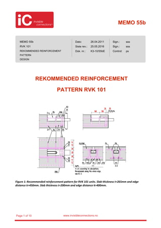
  • 1. MEMO 55b www.invisibleconnections.noPage 1 of 10 REKOMMENDED REINFORCEMENT PATTERN RVK 101 Figure 1: Recommended reinforcement pattern for RVK 101 units. Slab thickness t=265mm and edge distance k>450mm. Slab thickness t=200mm and edge distance k>400mm. MEMO 55b RVK 101 REKOMMENDED REINFORCEMENT PATTERN DESIGN Dato: Siste rev.: Dok. nr.: Sign.: Sign.: Control: 26.04.2011 25.05.2016 K3-10/55bE sss sss ps
  • 2. MEMO 55b www.invisibleconnections.noPage 2 of 10 Figure 2: Recommended reinforcement pattern for RVK 101 units. Slab thickness t=265mm and edge distance 180mm≤k≤450mm. Slab thickness t=200mm and edge distance 180mm≤k≤400mm. Ultimate limit load according to Figure 5.
  • 3. MEMO 55b www.invisibleconnections.noPage 3 of 10 Figure 3: Recommended reinforcement pattern for RVK 101 units. Slab thickness t<265mm and edge distance 180mm≤k<300mm. Ultimate limit load according to Figure 5.
  • 4. MEMO 55b www.invisibleconnections.noPage 4 of 10 The following comments can be made in connection with the recommended reinforcement pattern shown in Figure 1: • Reinforcement is illustrated in a slab with thickness 265mm, concrete cover 30mm and large edge distance. • In the area marked “c/c*)”, the tested elements (thickness t=265mm) were reinforced with P9 c/c 150mm along the whole edge. • Two stirrups P9 to be placed closed to the unit. One on each side. Edge reinforcement P9 beyond the prescribed locations should be in accordance with calculations. However, according to EC 2 clauses 6.4.2(5) and 9.3.1.4, stirrups continuously along the edge are always recommended. • Transverse reinforcement P5 in the bends of P9. When the concrete cover is 25mm, or less, the upper P5 bar can run above the half round steel in front of the unit. With 30mm concrete cover, the upper P5 bar may have to be cut. Then, a straight bar P8 is to be placed transverse of the unit as illustrated, in overlap with P5. If possible, the P5 bar should be made continuously. • The illustrated reinforcement is the necessary reinforcement required to transfer the forces in the unit to the concrete. It is not to be understood as the complete slab reinforcement. The main reinforcement for the slab/landings, inclusive edge reinforcement must be calculated in each case. The following comments can be made in connection with the recommended reinforcement pattern shown in Figure 2: • Reinforcement is illustrated in a slab with thickness 265mm, concrete cover 30mm and edge distance 180mm. • In the areas marked “c/c*)”, the tested elements (thickness t=265mm) were reinforced with P10 c/c 150mm and P9 c/c 150mm along the two edges. • Mesh reinforcement with transverse reinforcement P10 (closed bars) below. P10 runs above the unit, and below P1/P2. The mesh reinforcement may be replaced with straight bars with corresponding cross section area and c/c distance. • Slab thickness t=200mm: When the unit is located at 400mm, or closer to the corner than 400mm, stirrups shall always be used along both edges as prescribed (P9/P10). Slab thickness t=265mm: When the unit is located at 450mm, or closer to the corner than 450mm, stirrups shall always be used along both edges as prescribed (P9/P10). These stirrups anchor the main reinforcement, and will in addition function as shear reinforcement in the slab. Edge reinforcement P9/P10 beyond the prescribed locations should be in accordance with calculations. However, according to EC 2 clauses 6.4.2(5) and 9.3.1.4, stirrups continuously along the edge are always recommended. • P10 may be replaced with u-shaped stirrups in overlap with straight bars.
  • 5. MEMO 55b www.invisibleconnections.noPage 5 of 10 • The illustrated reinforcement is to be understood as a minimum of reinforcement which always should be found when the unit is located close to the corner. It is not to be understood as the complete slab reinforcement. The main reinforcement for the slab/landings, inclusive edge reinforcement must be calculated in each case. The following comments can be made in connection with the recommended reinforcement pattern shown in Figure 3: • Reinforcement is illustrated in a slab with thickness 200mm, concrete cover 30mm and edge distance 180mm. Notice the reduction in load in this case, see Figure 5. • In the areas marked “c/c*)”, the tested elements (thickness t=200mm) were reinforced with P10 c/c 150mm and P9 c/c 100mm along the two edges. • Mesh reinforcement with transverse reinforcement P10 (closed bars) below. P10 runs above the unit, and below P1/P2. The mesh reinforcement may be replaced with straight bars with corresponding cross section area and c/c distance. • Slab thickness t=200mm: When the unit is located at 400mm, or closer to the corner than 400mm, stirrups shall always be used along both edges as prescribed (P9/P10). Slab thickness t=265mm: When the unit is located at 450mm, or closer to the corner than 450mm, stirrups shall always be used along both edges as prescribed (P9/P10). These stirrups anchor the main reinforcement, and will in addition function as shear reinforcement in the slab. Edge reinforcement P9/P10 beyond the prescribed locations should be in accordance with calculations. However, according to EC 2 clauses 6.4.2(5) and 9.3.1.4, stirrups continuously along the edge are always recommended. • When the slab thickness is less than 265mm, and the unit is located closer to the corner than 300mm, stirrups P13 (shear reinforcement) may be used in the corner area, as illustrated, to increase the concrete capacity, see Figure 5. • P10 may be replaced with u-shaped stirrups in overlap with straight bars. • Transverse reinforcement 4Ø12 –P5 behind the unit as illustrated. • The illustrated reinforcement is to be understood as a minimum of reinforcement which always should be found when the unit is located close to the corner. However, is not to be understood as the complete slab reinforcement. The main reinforcement for the slab/landings, inclusive edge reinforcement must be calculated in each case.
  • 6. MEMO 55b www.invisibleconnections.noPage 6 of 10 General comments in connection with all reinforcement patterns: • Minimum slab thickness: t=200mm. Notice the reduction in load, see Figure 5. • P1 and P2 to be placed directly onto the unit, with the half round steel at top of the unit positioned in the bend of P1/P2. It is recommended to spot weld P1 and P2 to the unit in order to ensure the correct position. • Position, shape and anchorage of the stirrups P1 and P2 in the front is the governing factor concerning force transfer from the unit to the slab. Exact and careful detailing is therefore important. Inaccuracy may cause minor concrete cracks to develop before activating the reinforcement as assumed. • Transverse reinforcement in the bend of P1/P2 (P5). P5 shall have the same diameter as P1/P2 and should run along the whole width of the slab. • The transverse reinforcement P5 may be a part of the main transverse reinforcement and should have proper anchoring on the outside of the unit on both sides, especially towards the edge. This may require anchoring of P5 with an upward bend, or u-shaped bars. The required anchoring must be evaluated in every case. • P1 and P2 should be anchored to the maximum depth, depending on the slab thickness. • The inner width of the stirrups P1 and P2 should correspond to the width of the outer tube. This in order to have the most direct transfer of forces from the outer tube to the vertical legs of the stirrups. • The main reinforcement of the slab should have sufficient overlap with P1 and P2. This is illustrated with four straight bars P12. The total amount of main reinforcement must be calculated in each case. • All recommended reinforcement assumed to continue beyond the boundary of the illustrated area shall have a proper anchoring on the outside of the area. Thus, the reinforcement should continue at least one anchoring length outside the illustrated area, or be anchored by hooks. • Shear reinforcement due to punching shear according to EC 2, clause 6.4.3.
  • 7. MEMO 55b www.invisibleconnections.noPage 7 of 10 Tolerances on location of anchoring bars: Figure 4: Tolerances P1, P2 and P4. Figure 5: Slab thickness, recommended reinforcement pattern and load limitations. The coloured arrows refer to the recommended reinforcement patterns, as given in above Figures. The colour of the arrow giving the recommended reinforcement pattern corresponds to the colour of the line giving the load limitation. (In Memo 52, Figure 3, the load limitation is illustrated alone, without the arrows and references to reinforcement pattern)
  • 8. MEMO 55b www.invisibleconnections.noPage 8 of 10 Pos Diameter Cutting length Nr. Pr unit Bar schedule Grade 3) P1 12 1 Mandrel diameter=32mm (if this is in accordance with national regulations.) h=Decided locally, but as deep as possible. Normally: Slab thickness - 40mm - national rules for concrete cover. If the mandrel diameter is 4xØ (in accordance with EC-2) the width should be increased to 130mm to ensure good contact between the stirrups and the round steel. 500C (EC2, App C) P2 12 1 Mandrel diameter=32mm (if this is in accordance with national regulations.) h=Decided locally, but as deep as possible. Normally: Slab thickness - 40mm - national rules for concrete cover. If the mandrel diameter is 4xØ (in accordance with EC-2) the widths should be increased to respectively 130mm and 160 mm to ensure good contact between the stirrups and the round steel. 500C (EC2, App C) P4 12 2 h= Decided locally. Normally: Slab thickness – 30mm – 2 x national rules for concrete cover. 500C (EC2, App C) P5 12 2 62) Normally: Width of slab – 2 x national rules for concrete cover. 500C (EC2, App C) P6 12 1000 2 500C (EC2, App C) P7 12 1000 2 Slab thickness t=200mm: There is not enough space for the bars, and they don’t need to be used. 500C (EC2, App C)
  • 9. MEMO 55b www.invisibleconnections.noPage 9 of 10 Pos Diameter Cutting length Nr. Pr unit Bar schedule Grade 3) P8 12 1 Normally: Width of slab – 2 x national rules for concrete cover. Alternatively u-shaped or closed stirrups may be used. 500C (EC2, App C) P9 10 2 + 31) + 62) + h= Decided locally. Normally: Slab thickness –30mm – 2 x national rules for concrete cover. Recommended along whole edge. 500C (EC2, App C) P10 12 31), 2) + h= Decided locally. Normally: Slab thickness – 2 x national rules for concrete cover – thickness of mesh reinforcement. 500C (EC2, App C) P11 Minimum mesh reinforcement K131, or main reinforcement in both directions with corresponding cross section area and c/c. 500C (EC2, App C) P12 12 4 + 51), 2) + The amount of main reinforcement must be according to calculations in each case. Minimum 4xØ12 in overlap with P1/P2 as illustrated. Normally: Length of slab – 2 x national rules for concrete cover 500C (EC2, App C) P13 8 142) h= Decided locally. Normally: Slab thickness – 2 x national rules for concrete cover – thickness of mesh reinforcement. 500C (EC2, App C) 1) Edge distance≤400mm. Slab thickness, t=200mm. Edge distance≤450mm. Slab thickness, t=265mm. 2) Edge distance<300mm and slab thickness t<265mm. 3) Reinforcement steel of different ductility grade may be chosen provided that the bendability is sufficient for fitting the vertical suspension reinforcement to the half round steels in front of the unit. Table 1: List of reinforcement RVK 101.
  • 10. MEMO 55b www.invisibleconnections.noPage 10 of 10 REVISION HISTORY Date: Description: 26.04.2011 First Edition. 04.07.2011 Updated. 07.01.2016 Included revision history table. Included note on reinforcement ductility grade in Table 1. 25.05.2016 New template