Power Distribution Solutions for Buildings, Industry and Energy
•
0 likes•953 views

MCC,PDB,Lighting,BMS,VFD,PLC,Junction Boxes.

Recommended
More Related Content
What's hot
What's hot (19)
Similar to Power Distribution Solutions for Buildings, Industry and Energy
Similar to Power Distribution Solutions for Buildings, Industry and Energy (20)
Recently uploaded
Recently uploaded (20)
Power Distribution Solutions for Buildings, Industry and Energy
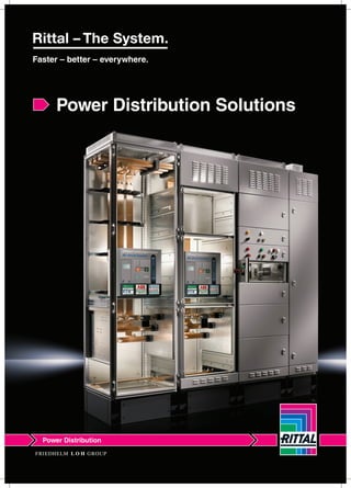
- 1. Power Distribution Solutions Power Distribution
- 2. Ri4Power structured system solutions for the reliable, fast assembly of low-voltage switchgear systems for machines, plant, and buildings. Rittal Ri4Power is the new name in low-voltage switchgear and distribution enclosures under a single roof in accordance with the worldwide standard (IEC 60 DIN and IEC 61 439-1/-2). High Current Distribution System up to 3200A Form 1 High Current Distribution System from 1600A to 5500A ISV Planning, Configuration, Selection Software Low-voltage switchgear with form separation upto 5500A Form 2-4 Ri4Power Form 2-402 Page Ri4Power Form 2-4...............................................................08 RiLine60 bus bar system ......................................................70 RiLine60 Aluminium bus bar system....................................129 Bus-mounting fuse bases....................................................132 RiLine60 bus bar system for DC system...............................138 Ri4Power ISV.......................................................................146 Technical specifications.......................................................167 Power Distribution
- 3. Buildings, Infrastructure • Schools • Banks • Insurance companies • Data centres • Football stadiums • Hospitals • Festival halls and exhibition buildings • Airports Process Industry • Sewage treatment plant • Heavy industry(mining, iron, steel) • Cement works • Waste disposal industry • Paper industry • Chemicals, petrochemicals • Pharmaceutical industry Industrial Plants • Automotive industry • Mechanical engineering • Shipbuilding, Marine engineering • Small power plants • Wind and Solar power • Biomass power plants Energy Generation Circuit-breaker section1 • For switchgear from all well-known manufacturers such as Siemens, ABB Mitsubishi, Moeller, Merlin Gerin, Terasaki, GE • Use of air and moulded case circuit-breakers Form 2-4: Universal in best form Coupling section • Combination of a circuit breaker section with a space-saving busbar riser • Separation into individual busbar sections to boost equipment availability 2 3 Outgoing section • Flexible design of the interior installation • Fully insulated distribution busbars with extensive connection system Cable chamber • Available from a field width of 300mm • Optional cable entry from above or below • Flexible installation with Rittal system accessories 4 Switch-disconnector-fuse section • For switchgear from Jean Müller, Moeller, ABB, Siemens • Also suitable for installation of equipment modules from Jean Müller. NEW 5 Ri4Power Form 2-4 03
- 4. Ri4Power Form 2-4 – An individual system for the configuration of type-tested low-voltage switchgear with inner form separation. The flexible combination of Ri4Power field types supports optimum configuration for your applications. Ri4Power Form 2-404
- 5. Form 2-4: Switchgear with a high level of safety • Tested connection system • Clear arrangement of the cable connection points • Contacting system with no drilling required • Space-optimised configuration, even for smaller rated currents Cable connection1 • An extensive range of accessories to cover the busbar • Fully insulated busbar connection • Connection accessories for every type of conductor Busbar infeed2 • Connection accessories for every type of conductor • Unobstructed access to the busbar compartment from the front • For the side in feed of compartments Side busbar riser3 Modular outgoing section • Safe compartmentalisation • Logically structured layout of functional units • Access control, thanks to lockable partial doors • Combination of control units and power outlet within one enclosure is supported 4 Cable chamber enclosure • Various options for structured cable routing • Safe shielding from the compartments • Solid shielding from the main busbar system 5 Ri4Power Form 2-4 05 • Type-tested to the internationally valid standard IEC 60 439-1 • Design verification to IEC 61 439-1/-2 • Tests with ASTA certification • Tested accidental arcing protection to IEC 61 641 • Protection category up to IP 54 • Prevention of accidental arcing 6 Tested safety
- 6. Ri4Power Form 2-4 offers the best possible operator protection. Thanks to extensive busbar insulation and sub-division of the compartments, the occurrence and spread of accidental arcs is largely prevented. Ri4Power Form 2-406
- 7. Ri4Power Form 2-4 07
- 9. Ri4Power Form 1-4 Modular system....Page 8 to 69 • For low-voltage switchgear with design certificate to IEC61439-1/-2 and DIN EN 61 439-1/-2 • For control systems and power distributions • Structured system solution for switchgear with Form separation 1-4b • Simple, installation-friendly system assembly Busbar systems up to 5500 A • RiLine60 – The compact busbar system up to 1600 A • Maxi-PLS – The assembly-friendly system • Flat-PLS – The flat bar system for discerning requirements • Tested PE conductor system • High levels of short-circuit resistance up to 100 kA for 1 sec./220 kA Modular enclosure system • Based on enclosure platform TS 8 • Flexible, modular front design • Roof plates to suit every requirement • Modular compartment configuration for internal compartmentalisation up to Form 4b • Internal cover plates, contact hazard protection for air circuit-breaker and NH switch-disconnector fuse sections • Accessories for Ri4Power Simple planning • Power Engineering 6.1 SV 3020.500 • Configuration of low-voltage switchgear with design certificate • Simple, fast assembly with automatically generated assembly plan • Generation of parts lists with graphical output Ri4Power Form 2-4 09
- 10. 2 2 2 SV-TS 8 Modular Enclosures (Height 1800 mm) Baying Systems TS 8 SU 1 St. 400 1800 400 9792.460 NA 600 1800 400 9792.472 NA 800 1800 400 9792.484 NA 400 1800 600 9792.461 42 600 1800 600 9792.473 53 800 1800 600 9792.485 58 400 1800 800 9792.462 49 600 1800 800 9792.474 62 800 1800 800 9792.486 NA Elements front and rear Plinth Trim side Plinth Height 100 mm Height 200 mm Height 100 mm Height 200 mm 1 set 1 set 1 set 1 set 8601.400 NA 8601.040 NA 8601.600 NA 8601.040 NA 8601.800 NA 8601.040 NA 8601.400 NA 8601.060 NA 8601.600 NA 8601.060 NA 8601.800 NA 8601.060 NA 8601.400 NA 8601.080 NA 8601.600 NA 8601.080 NA 8601.800 NA 8601.080 NA Flex-Block Leveling element for socket Also required Weight (kg) Width mm Height mm Depth mm No. SV Side Panel Protection Category Roof panels for Protection/Version Roof plates for gland plates Roof plates with pressure relief valve Faceplates for Protection Upgrade kit for front panel IP 2X Partial doors for clearance at front panel 100/100 mm Front panel above 300 mm/ below100 mm for Protection Front panel above 100 mm/ below 300 mm for Protection Upgrade kit for 300/100 mm front panel IP 2X IP 43 Partial doors for clearance at front panel 300/100 mm Rear bottom cover Baying bracket Baying outside IP 55 IP 55 /closed IP 43 /ventilated IP 2X /ventilated IP 55 IP 43 IP 54/1 set of closed IP 2X ventilated/1set IP 54/1 set of closed IP 2X ventilated 2 St. 1 St. 1 St. 1 St. 1 St. 1 St. 1 set 1 St. 1 set 1 St. 1 St. 4 St. 6 St. 8800.430 8800.490 8800.430 8800.490 8800.430 8800.490 8800.430 8800.490 8800.430 8800.490 8800.430 8800.490 8800.430 8800.490 8800.430 8800.490 8800.430 8800.490 8184.235 9790.452 NA NA NA NA 9671.044 9671.156 9672.054 9671.156 8186.235 9790.453 NA NA NA NA 9671.046 9671.176 9672.056 9671.176 8188.235 9790.454 NA NA NA NA 9671.048 9671.196 9672.058 9671.196 8184.235 9790.452 NA NA NA NA 9671.044 9671.156 9672.054 9671.156 8186.235 9790.453 NA NA NA NA 9671.046 9671.176 9672.056 9671.176 8188.235 9790.454 NA NA NA NA 9671.048 9671.196 9672.058 9671.196 8184.235 9790.452 NA NA NA NA 9671.044 9671.156 9672.054 9671.156 8186.235 9790.453 NA NA NA NA 9671.046 9671.176 9672.056 9671.176 8188.235 9790.454 NA NA NA NA 9671.048 9671.196 9672.058 9671.196 Base Colour: RAL 7035 Protection category: Up to IP 54, depending on the panels. Testing: - Design certificate to IEC 61 439-1/-2 - IEC 61 641 Detailed drawings/ Technical information: Available on the Internet. Photo shows a configuration example with equipment not included in the scope of supply. Supply includes: - Enclosure frame - Bottom 3mm single - Top cover solid Material: Sheet steel Surface finish: - Enclosure frame: Dipcoat-primed - Door(s), roof, Dipcoat-primed, powder- coated on outside textured paint - Gland plates: RAL 7035 textured finish Ri4Power Form 2-410 gland plate with cover See page 26 See page 26 See page 26 See page 26 See page 26 IP 54 /closed IP 2X /ventilated
- 11. Baying Systems TS 8 2 Weight (kg) Width mm Height mm Depth mm No. SV Flex-Block Leveling element for socket Also required Side Panel Protection Category Roof panels for Protection/Version Roof plates for gland plates Roof plates with pressure relief valve Faceplates for Protection Upgrade kit for front panel IP 2X Partial doors for clearance at front panel 100/100 mm Front panel above 300 mm/below100 mm for Protection Front panel above 100 mm/below 300 mm for Protection Upgrade kit for 300/100 mm front panel IP 2X Partial doors for clearance at front panel 300/100 mm IP 55 IP 55 /closed IP 43 /ventilated IP 2X /ventilated IP 55 IP 54 /closed IP 2X /ventilated IP 43 IP 54/1 set of closed IP 2X ventilated/1set IP 54/1 set of closed IP 2X ventilated SV-TS 8 Modular Enclosures (Height 2000 mm) SU 1 St. 400 2000 400 9792.464 600 2000 400 9792.476 800 2000 400 9792.488 400 2000 600 9792.465 600 2000 600 9792.477 800 2000 600 9792.489 Base Elements front and rear Trim side Height 100 mm 1 set 8601.400 8601.600 8601.800 8601.400 8601.600 8601.800 Height 200 mm 1 set 8602.400 8602.600 8602.800 8602.400 8602.600 8602.800 Height 100 mm 1 set 8601.040 8601.040 8601.040 8601.060 8601.060 8601.060 Height 200 mm 1 set 8602.040 8602.040 8602.040 8602.060 8602.060 8602.060 IP 43 2 St. 1 set 1 set 8184.235 9790.452 9671.744 8186.235 9790.453 9671.764 8188.235 9790.454 9671.784 8106.235 9671.646 9671.746 8601.235 9671.666 9671.766 8106.235 9671.686 9671.786 AOR AOR AOR 9671.846 9660.235 9660.245 9671.546 9665.903 9671.586 NA NA NA 9671.446 9660.935 9660.945 9671.044 9671.156 9672.054 9671.156 9671.176 9672.056 9671.176 9671.046 9671.048 9671.044 9671.046 9671.048 9671.196 9671.158 9671.178 9671.198 9672.058 9671.196 9671.156 9672.054 9672.056 9671.176 9672.058 9671.196 AOR- Available on request Weight (kg) Width mm Height mm Depth mm No. SV Flex-Block Leveling element for socket Also required Side Panel Protection Category Roof panels for Protection/Version Roof plates for gland plates Roof plates with pressure relief valve Faceplates for Protection Upgrade kit for front panel IP 2X Partial doors for clearance at front panel 100/100 mm Front panel above 300 mm/below100 mm for Protection Front panel above 100 mm/below 300 mm for Protection Upgrade kit for 300/100 mm front panel IP 2X Partial doors for clearance at front panel 300/100 mm IP 55 IP 55 /closed IP 43 /ventilated IP 2X /ventilated IP 55 IP 54 /closed IP 2X /ventilated IP 43 IP 54/1 set of closed IP 2X ventilated/1set IP 54/1 set of closed IP 2X ventilated 2 SV-TS 8 Modular Enclosures (Height 2000 mm) SU 1 St. 400 2000 9792.466 600 2000 9792.478 800 2000 9792.490 400 2000 9792.467 600 2000 9792.479 800 2000 9792.491 Base Elements front and rear Trim side Height 100 mm 1 set 8601.400 8601.600 8601.800 8601.400 8601.600 8601.800 Height 200 mm 1 set 8602.400 8602.600 8602.800 8602.400 8602.600 8602.800 Height 100 mm 1 set 8601.080 8601.080 8601.080 8601.015 8601.010 8601.015 Height 200 mm 1 set 8602.080 8602.080 8602.080 8602.080 8602.080 8602.080 IP 43 2 St. 1 set 1 set 800 800 800 1000 1000 1000 NA NA NA NA NA NA 8108.235 9671.648 9671.748 9671.848 9671.548 9671.448 9671.044 9671.158 9672.054 9671.156 Partial doors for Modular Construction Baying bracket Baying outside 8800.430 8800.490 8800.430 8800.490 8800.430 8800.490 8800.430 8800.490 8800.430 8800.490 1 St. 4 St. 6 St. 8800.430 8800.490 8108.235 9671.668 9671.768 9659.525 9671.568 9671.468 9671.046 9671.178 9672.056 9671.176 8108.235 9671.688 9671.788 9659.535 9671.588 9671.488 9671.048 9671.198 9672.058 9671.196 8100.235 9790.455 9671.044 9671.158 9672.054 9672.156 8100.235 9790.456 9671.046 9671.178 9672.056 9672.176 8100.235 9790.457 9671.048 9671.198 9672.058 9672.196 Ri4Power Form 2-4 11 See page 26 See page 26 See page 26 See page 26 See page 26 See page 26 See page 26 See page 26 See page 26 See page 26
- 12. Baying Systems TS 8 2 SV-TS 8 Modular Enclosures (Height 2200 mm) 2 Weight (kg) Width mm Height mm Depth mm No. SV Flex-Block Leveling element for socket Also required Side Panel Protection Category Roof panels for Protection/Version Roof plates for gland plates Roof plates with pressure relief valve Faceplates for Protection Upgrade kit for front panel IP 2X Partial doors for clearance at front panel 100/100 mm Front panel above 300 mm/below 100 mm for Protection Front panel above 100 mm/below 300 mm for Protection Upgrade kit for 300/100 mm front panel IP 2X IP 43 Partial doors for clearance at front panel 300/100 mm SV-TS 8 Modular Enclosures (Height 2200 mm) SU 1 St. 400 2200 9792.470 600 2200 9790.482 800 2200 9792.494 400 2200 9792.471 600 2200 9792.483 800 1000 2200 2200 9792.495 9792.507 Base Elements front and rear Trim side 8601.600 8601.800 8601.400 8601.600 8601.800 8601.800 8602.600 8602.800 8601.080 8601.080 8601.015Spl 8601.015Spl 8601.015Spl8601.015Spl Height 100 mm Height 200 mm Height 100 mm Height 200 mm 1 set 1 set 1 set 1 set 8601.400 8602.400 8601.080 8602.080 8602.080 8602.080 IP 55 IP 55 /closed IP 43 /ventilated IP 2X /ventilated IP 55 IP 54 /closed IP 2X /ventilated IP 43 IP 54/1 set of closed IP 2X ventilated/1set IP 54/1 set of closed IP 2X ventilated 800 800 800 1000 1000 1000 1000 NA NA NA NA NA NA NA NA NA NA NA NA NA NA NA Partial doors for Modular Construction Baying bracket Baying outside 2 St. 8128.235 8128.235 8128.235 8120.235 9790.201 9790.201 9790.201 1 St. 9671.648 9671.668 9671.688 9790.455 9790.456 9790.457 9790.458 1 St. 9671.748 9671.768 9671.788 NA NA NA NA 1 St. 9671.848 9659.525 9659.535 NA NA NA NA 1 St. 9671.548 9671.568 9671.588 NA NA NA NA 1 St. 9671.448 9671.468 9671.488 NA NA NA NA 1 set 9671.044 9671.046 9671.048 9671.044 9671.046 9671.048 9790.616 1 St. 9671.150 9671.170 9671.190 9671.150 9671.170 9671.190 9787.989 1 set 9672.054 9672.056 9672.058 9672.054 9672.056 9672.058 9672.050 1 St. 1 St. 9671.158 9671.178 9671.198 9671.158 9671.178 9671.198 9787.988 4 St. 8800.430 8800.430 8800.430 8800.430 8800.430 8800.430 8800.430 6 St. 8800.490 8800.490 8800.490 8800.490 8800.490 8800.490 8800.490 Weight (kg) Width mm Height mm Depth mm No. SV Flex-Block Leveling element for socket Also required Side Panel Protection Category Roof panels for Protection/Version Roof plates for gland plates Roof plates with pressure relief valve Faceplates for Protection Upgrade kit for front panel IP 2X Partial doors for clearance at front panel 100/100 mm Front panel above 300 mm/below100 mm for Protection Front panel above 100 mm/below 300 mm for Protection Upgrade kit for 300/100 mm front panel IP 2X Partial doors for clearance at front panel 300/100 mm IP 55 IP 55 /closed IP 43 /ventilated IP 2X /ventilated IP 55 IP 54 /closed IP 2X /ventilated IP 43 IP 54/1 closed IP 2X ventilated IP 54/closed IP 2X ventilated SU 1 St. 400 400 9792.468 600 400 9792.480 800 400 9792.492 400 600 9792.469 600 600 9792.481 800 600 9792.493 Base Elements front and rear Trim side Height 100 mm 1 set 8601.400 8601.600 8601.800 8601.400 8601.600 8601.800 Height 200 mm 1 set 8602.400 8602.600 8602.800 Height 100 mm 1 set 8601.040 8601.040 8601.040 8601.060 8601.060 8601.060 Height 200 mm 1 set 8602.060 8602.060 8602.060 IP 43 AOR- Available on request 2200 2200 2200 2200 2200 2200 NA NA NA NA NANA 43.2 54.0 59.4 NA NANA 2 St. 9790.428 9790.428 9790.428 8126.235 8126.235 8126.235 1 St. 1 St. 1 St. 1 St. 1 St. 1 set 1 St. 1 St. 1 set 9790.452 NA NA NA NA 9671.044 9671.150 9790.453 NA NA NA NA 9671.046 9671.170 9790.454 NA NA NA NA 9671.048 9671.190 9671.646 9671.666 9671.686 9671.746 9671.766 9671.786 9671.846 9660.235 9660.245 9671.546 9665.903 9671.586 9671.446 9660.935 9660.945 9671.044 9671.046 9671.048 9671.150 9671.170 9671.190 9672.054 9672.056 9672.058 9671.158 9671.178 9671.198 9671.158 9671.178 9671.198 9672.054 9672.056 9672.058 Ri4Power Form 2-412 See page 26 See page 26 See page 26 See page 26 See page 26 See page 26 See page 26 See page 26 See page 26 See page 26 See page 26 See page 26
- 13. Test: - Design certificate to IEC61 439-1/-2 - IEC 61 641 Detailed drawings / Technical information: Available on the Internet. Photo shows a configuration example with equipment not included in the scope of supply. Material: Sheet steel Surface: - Enclosure frame: Dipcoat-primed - Door(s), Dipcoat-primed, powder coated on outside - Gland plates: RAL 7035 textured finish Color: RAL 7035 Protection category: Up to IP 54, depending on the panels. Supply includes: - Enclosure frame - Door, 3 mm double bit- lock insert - Bottom 3mm single gland plate cover 3 SV-TS 8 Cable Chamber Enclosures (Height 1800 mm) Baying Systems TS 8 Ri4Power Form 2-4 13Ri4Power Form 2-4 IP 43 Door (S) Width mm Height mm Depth mm No. SV Leveling element for socket SU 1 St. Base Elements front and rear Trim side Height 100 mm Height 200 mm Height 100 mm Height 200 mm 1 set 1 set 1 set 1 set Weight (kg) 300 1800 400 9792.400 1 NA 400 1800 400 9792.412 1 NA 300 1800 600 9792.401 1 47.0 400 1800 600 9792.413 1 49.5 300 1800 800 9792.402 1 NA 400 1800 800 9792.414 1 NA 8601.915 8602.915 8601.915 8602.915 8601.400 8602.400 8601.040 8602.040 8601.915 8602.915 8601.060 8602.060 8601.400 8602.400 8601.060 8602.060 8601.915 8602.915 8601.080 8602.080 8601.400 8602.400 8601.080 8602.080 Also required Accessories Equipment cabinet Function room facilities Alternative closure systems 2 St. St.1 St.1 St.1 St.1 1 St. 1 set 4 St. 6 St. 8186.235 9790.647 9671.736 - 9671.536 - - 8800.430 8800.490 8186.235 9790.649 9671.766 9660.235 9665.903 9660.935 9672.056 8800.430 8800.490 8186.235 9790.646 9671.736 - 9671.536 - - 8800.430 8800.490 8186.235 9790.646 9671.746 9671.846 9671.546 9671.446 9672.054 8800.430 8800.490 8188.235 9671.638 9671.738 NA 9671.538 NA 8800.430 8800.490 - 8188.235 9671.648 9671.748 9671.848 9671.548 9671.448 9672.054 8800.430 8800.490 Baying bracket Baying outside Upgrade kit for 300/100 mm Front panel IP 2X Front panel above 100 mm / below 300 mm for Protection Front panel above 300 mm / below 100 mm for Protection Roof plates with pressure relief valve Roof plates for gland plates Roof panels for Protection / Version Side Panel Protection Category IP 55 IP 55/closed IP 43/ventilated IP 2X/ventilated IP 55 IP 54/closed IP 2X/ventilated IP 54/closed IP 2X/ventilated See page 26 See page 26 See page 26 See page 26 3
- 14. 3 SV-TS 8 Cable Chamber Enclosures (Height 2000 mm) Baying Systems TS 8 3 SV-TS 8 Cable Chamber Enclosures (Height 2200 mm) Ri4Power Form 2-414 IP 43 Door (S) Width mm Height mm Depth mm No. SV Leveling element for socket SU 1 St. Base Elements front and rear Trim side Height 100 mm Height 200 mm Height 100 mm Height 200 mm 1 set 1 set 1 set 1 set Weight (kg) 300 400 1 NA 400 400 1 NA 300 600 1 400 600 1 300 800 1 400 800 1 Also required 1 set Upgrade kit for 300/100 mm Front panel IP 2X Front panel above 100 mm / below 300 mm for Protection Front panel above 300 mm / below 100 mm for Protection Roof plates with Pressure relief valve Roof plates for gland plates Roof panels for Protection / Version Side Panel Protection Category IP 55 IP 55/closed IP 43/ventilated IP 2X/ventilated IP 55 IP 54/closed IP 2X/ventilated IP 54/closed IP 2X/ventilated 2000 2000 2000 2000 9792.405 9792.417 9792.406 9792.418 48.5 53.8 50.4 55.9 2000 9792.404 2000 9792.416 8601.915 8602.915 8601.040 8602.040 8601.400 8602.400 8601.040 8602.040 8601.915 8602.915 8601.060 8602.060 8601.400 8602.400 8601.060 8602.060 8601.915 8602.915 8601.080 8602.080 8601.400 8602.400 8601.080 8602.080 8108.235 9671.648 9671.748 9671.848 9671.548 9671.448 9672.054 8106.235 9671.638 9671.738 9671.538 Partial doors for clearance at Front panel 300/100 mm 2 St. 1 St. 1 St. 1 St. 1 St. 1 St. 1 set 8106.235 9671.646 9671.746 9671.846 9671.546 9671.446 9672.054 8106.235 9671.636 9671.736 9671.536 8601.235 9790.648 9791.744 9671.846 9671.546 9671.446 9672.054 9671.156 9671.156 9671.156 8601.235 9790.647 9671.734 9671.536 IP 43 Door (S) Width mm Height mm Depth mm No. SV Leveling element for socket SU 1 St. Base Elements front and rear Trim side Height 100 mm Height 200 mm Height 100 mm Height 200 mm 1 set 1 set 1 set 1 set Weight (kg) 300 400 1 NA 400 400 1 NA 300 600 1 400 600 1 300 800 1 400 800 1 Also required Upgrade kit for 300/100 mm front panel IP 2X Front panel above 100 mm / below 300 mm for Protection Front panel above 300 mm / below 100 mm for Protection Roof plates with Pressure relief valve Roof plates for gland plates Roof panels for Protection / Version Side Panel Protection Category IP 55 IP 55/closed IP 43/ventilated IP 2X/ventilated IP 55 IP 54/closed IP 2X/ventilated IP 54/closed IP 2X/ventilated 2000 2000 2000 2000 48.5 53.8 50.4 55.9 2000 2000 8601.915 8602.915 8601.040 8602.040 8601.400 8602.400 8601.040 8602.040 8601.915 8602.915 8601.060 8602.060 8601.400 8602.400 8601.060 8602.060 8601.915 8602.915 8601.080 8602.080 8601.400 8602.400 8601.080 8602.080 8108.235 9671.648 9671.748 9671.848 9671.548 9671.448 9672.054 2 St. 1 St. 1 St. 1 St. 1 St. 1 St. 1 set 8106.235 9671.646 9671.746 9671.846 9671.546 9671.446 9672.054 8106.235 9671.636 9671.736 9671.536 8601.235 9790.647 9671.734 9671.536 9792.408 9792.420 9792.409 9792.421 9792.410 9792.422 8601.235 9790.648 9791.744 9671.846 9671.546 9671.446 9672.054 9671.158 9671.158 9671.156 8128.235 9671.638 9671.738 9671.538 Partial doors for clearance at front panel 300/100 mm 1 set Accessories Equipment cabinet Function room facilities Alternative closure systems 4 St. 6 St. 8800.430 8800.490 8800.430 8800.490 8800.430 8800.490 8800.430 8800.490 8800.430 8800.490 8800.430 8800.490 Baying bracket Baying outside Accessories Equipment cabinet Function room facilities Alternative closure systems See page 26 See page 26 See page 26 See page 26 See page 26 See page 26 See page 26 See page 26
- 15. SV-TS 8 Enclosure (Height 1800 mm)Busbar SU 1 St. 4 Width mm Height mm Depth mm No. SV Side panel SV-TS 8 Busbar Enclosure (Height 2000 mm) SU 1 St. 4 Width mm Height mm Depth mm No. SV Side panel SV-TS 8 Busbar Enclosure (Height 2200 mm) SU 1 St. 4 Width mm Height mm Depth mm No. SV Side panel 1 set 4 6 4 Test: - Design verification IEC 61 439-1/-2 - IEC 61 641 Detail drawings / Technical Information: Available on the Internet. Photo shows a configuration example with equipment not included in the scope of supply. Material: Sheet steel Surface: − Enclosure frame: Dipcoat primed − Roof, front bolted cover, Dipcoat- primed, powder coated on the outside, textured paint Color: RAL 7035 Protection: Up to IP 54 Delivery: - Enclosure frame - Front bolted cover - Bottom cover same as top cover 300 1800 400 9792.430 300 1800 600 9792.431 300 1800 800 9792.432 400 1800 400 9792.442 400 1800 600 9792.443 400 1800 800 9792.444 300 1800 1000 9792.433 400 1800 1000 9792.445 300 2000 400 300 2000 600 300 2000 800 400 2000 400 400 2000 600 400 2000 800 300 2000 1000 400 2000 1000 9792.434 9792.435 9792.436 9792.446 9792.447 9792.448 9792.437 9792.449 300 2200 400 300 2200 600 300 2200 800 400 2200 400 400 2200 600 400 2200 800 300 2200 1000 400 2200 1000 9792.438 9792.439 9792.440 9792.450 9792.451 9792.452 9792.441 9792.455 Socket1) Also required Accessories Function room facilities 1) The busbar is connected to the main cabinet on a steel base, i.e. the steel base of the main cabinet is 200 mm wide select. Coupling set mounting kit Angular baying brackets Baying connectors, external 8184.235 8186.235 8188.235 8184.235 8186.235 8188.235 8180.235 8180.235 8104.235 8106.235 8108.235 8104.235 8104.235 8104.235 8100.235 8100.235 8790.428 8126.235 9790.428 8128.235 9790.4299790.4298128.235 9674.036 9674.038 9674.046 9674.048 8800.430 8800.430 8800.430 8800.430 8800.430 8800.430 8800.430 8800.430 8800.490 8800.490 8800.490 8800.490 8800.490 8800.490 8800.490 8800.490 8128.235 Baying Systems TS 8 Ri4Power Form 2-4 15
- 16. 5 5 SV-TS 8 Isolators Cabinet (Height 2000 mm) SU 1000 1200 1000 1200 2000 2000 2000 2000 600 600 800 800 1 St. 9792.501 9792.509 9792.502 9792.510 1 1 1 1 97.0 116.0 104.0 123.0 Height 100 mm 1 set 8601.000 8601.200 8601.000 8601.200 Height 200 mm 1 set 8602.000 8602.200 8602.000 8602.200 Height 100 mm 1 set 8601.060 8601.060 8601.080 8601.080 Height 200 mm 1 set 8602.060 8602.060 8602.080 8602.080 Flex-Block IP 55 2 St. 8106.235 8106.235 8108.235 8108.235 IP 3X 1 set 9674.340 9674.340 9674.340 9674.340 IP 3X 1 set 9674.342 9674.342 9674.342 9674.342 1 set 9674.362 9674.366 9674.364 9674.368 1 set 9674.372 9674.376 9674.372 9674.376 1 St. 9674.350 9674.350 9674.350 9674.350 1 St. 9674.356 9674.356 9674.356 9674.356 1 St. 9674.306 9674.306 9674.308 9674.308 1 St. 9674.305 9674.305 9674.307 9674.307 4 St. 8800.430 8800.430 8800.430 8800.430 6 St. 8800.490 8800.490 8800.490 8800.490 1) 1 St. 9660.255 9660.265 9659.545 9659.555 1) 2) 1 St. 9660.955 9660.965 – – 1) In exchange for the TS series roof 2) Other sizes available on request. 5 Width mm Height mm Depth mm No. SV Door (S) Weight (kg) Base Elements front and rear Trim side Leveling element for socket Also required Jean Müller ABB / Siemens Partition for Isolators field Baying outside Admission rate for Do Contact Protection Cable Chamber Front panel above 186 mm / below 336 mm for Protection Front panel above 336 mm / below 136 mm for Protection Side Panel Protection Category Rear area Roof area Baying bracket Accessories Roof plates with pressure relief valve Equipment cabinet Function Room Setup Roof panels for Protection/Version IP 2X/ventilated SAS in the roof area SAS in the rear area Test: - Design verification IEC 61 439- 1/-2 - IEC 61 641 Detail drawings / Technical Information: Found on the Internet. Photo shows an expansion example, does not meet the delivery form. Material: Sheet steel Surface: - Enclosure frame: primed - Door (s), roof, primed, powder- coated, textured paint - Floor plates: RAL 7035 textured finish Color: RAL 7035 Protection: IP 3X depending on the planking. Delivery: - Enclosure frame - Door (s), 3 mm Double bit- lock insert - Solid top cover - Bottom 3 mm single gland plate with cover Baying Systems TS 8 Ri4Power Form 2-416
- 17. 4 SV-TS 8 Isolators Cabinet (2200 mm) Side panels Walls 400 Side panels, screw-fastened, sheet steel for TS • Automatic potential equalisation and higher EMC protection thanks to enclosure panel holders with earthing insert • Easy positioning with the location aid • Earthing bolt with contact surface Material: Sheet steel 1.5 mm, textured Surface finish: Dipcoat-primed, powder-coated on the outside Colour: RAL 7035 Protection category: IP 55 to IEC 60 529 Supply includes: Assembly parts. Note: Enclosure panel holders may optionally be fitted from the inside or outside of the enclosure. Area available for population: External dimension – 100 mm. Automatic potential equalisation Accessories: • Earth straps • Enclosure panel holders, internal, for heavy installed equipment and high dynamic pressures. 1 For enclosures Packs of Model No.TS Height mm Depth mm 1800 400 2 8184.235 1800 600 2 8186.235 1800 800 2 8188.235 1800 1000 2 8180.235 2000 400 2 8104.235 2000 600 2 8106.235 2000 800 2 8108.235 2000 1000 2 8100.235 2200 2 9792.720 2200 600 2 8126.235 2200 800 2 8128.235 2200 1000 9792.7212 Baying Systems TS 8 SU 1000 1200 1000 1200 2200 2200 2200 2200 600 600 800 800 1 St. 9792.505 9792.512 9792.506 9792.513 1 1 1 1 102.0 122.0 109.0 129.0 Height 100 mm 1 set 8601.000 8601.200 8601.000 8601.200 Height 200 mm 1 set 8602.000 8602.200 8602.000 8602.200 Height 100 mm 1 set 8601.060 8601.060 8601.080 8601.080 Height 200 mm 1 set 8602.060 8602.060 8602.080 8602.080 Width mm Height mm Depth mm No. SV Door (S) Weight (kg) Flex-Block Base Elements front and rear Trim side Leveling Element for socket Ri4Power Form 2-4 17 Rear Bolted covers Rear Bolted, screw-fastened, sheet steel for TS • Easy positioning with the location aid • Earthing bolt with contact surface Material: Sheet steel 1.5 mm, textured Surface finish: Dipcoat-primed, powder-coated on the outside Colour: RAL 7035 Protection category: IP 54 to IEC 60 529 Supply includes: Assembly parts. For enclosures Packs of Model No.TS Width mm Height mm 300 300 300 400 400 400 600 600 600 800 800 800 1000 1000 1000 1200 1800 2000 2200 1800 2000 2200 1800 2000 2200 1800 2000 2200 1800 2000 2200 1600 9792.700 9792.701 9792.702 9790.729 9792.703 9792.704 9792.705 9792.706 9792.707 9792.708 9792.709 9792.710 9792.711 9792.712 9792.713 9792.900 1 1 1 1 1 1 1 1 1 1 1 1 1 1 1 1
- 18. Form 2-4 compartment Time-saving system assembly Side panel modules The side panel modules form the basic element for internal installation. One-person assembly: Locate components into the TS 8 pitch pattern, and release. Both hands are now free for the next installation step. The modular installation con- cept enables optimum utilisa- tion of the assembly area, thanks to compartment heights in small increments (150, 200, 250 mm, etc.). The proven TS 8 pitch is used for many Ri4Power components and permits the use of TS 8 system accessories. Partial doors and cross members Simple assembly and high quality standards characterise the new partial door system. Thanks to the new design, the cross member may also be retro-fitted. Fitting accuracy and precision are prerequisites for modular technology. The hinge of the partial doors is mounted on the TS 8 frame without any holes needing to be drilled. Mini-TS profile Mini-TS profile - the TS pitch in the smallest dimension. An extension of the assembly spectrum for small and medium loads. The three assembly sides of the Mini-TS profile ensure the versatility and fast assembly technology of the TS 8 enclosure profile at all times, whatever the location. The connector pieces always provide an attachment point at every position in the 25 mm pitch, irrespective of the mounting angle used. The small size means the Mini-TS bars can be mounted without conflict in the internal and external mounting level of the TS 8 enclosure. Ri4Power Form 2-418
- 19. Form 1-4 Compartment configuration Attachment set for air circuit-breaker installation For attaching air circuit-breakers (ACB) to air circuit-breaker support bars. Material: Sheet steel, zinc-plated Supply includes: 4 threaded plates (M8/M12). Packs of Model No. SV 1 set 9660.970 Assembly parts. Mounting bracket for functional space divider • The mounting bracket is secured − to the TS frame, − to the side panel module or − between a frame section and an auxiliary construction. • Pre-machined mounting openings allow slide-in attachment of functional space dividers. Material: Sheet steel, zinc-plated, passivated,1.5 mm Supply includes: For functional space depth mm Length mm Packs of Model No. SV 400 352 2 9792.855 600 552 2 9792.856 800 752 2 9792.857 1) In conjunction with vertical busbar space separation. 1000 952 2 9792.858 Mounting bracket for functional space divider and air circuit-breaker support rail • The mounting bracket is secured to the side panel module. • Pre-machined mounting openings allow slide-in attachment of functional space dividers. • The air circuit-breaker support bar may be attached to the upper level. Material: Sheet steel, zinc-plated, passivated, 2 mm Supply includes: Assembly parts. Also required: − Functional space side panel modules, − Air circuit-breaker support rail, For functional space depth mm Length mm Model No. SV 400 352 2 9792.590 600 552 2 9792.591 800 752 2 9792.592 Packs of 1000 952 2 9792.593 Air circuit-breaker support bar • For the configuration of air circuit-breakers (ACB) in compartments. • The support rail is secured using a mounting bracket. Material: Sheet steel, zinc-plated, passivated, 2.5 mm Supply includes: Assembly parts. Also required: − Mounting bracket for functional space divider and air circuit-breaker support bar − Attachment set for air circuit-breaker installation For enclosure width mm Length mm Model No. SV 400 351 2 9673.004 600 551 2 9673.006 800 751 2 9673.008 Packs of 2 9792.596 2 9792.597 1000 951 1200 1151 Ri4Power Form 2-4 19
- 20. Partial doors for SV -TS Door hinges with non-drilled internal fastening. Door may be optionally hinged on the right or left. Material: Sheet steel, 2 mm Surface finish: Textured Colour: RAL 7035 Supply includes: Hinges and assembly parts. Also required: − Twist locks, − Cross members for SV-TS, For enclosure width 400 mm For enclosure width 600 mm Height mm No. of locks required Packs of Model No. SV 150 1 1 200 1 1 250 1 1 300 1 1 400 1 1 600 2 1 800 2 1 1000 3 1 1600 3 1 1800 3 1 2000 3 1 Height mm No. of twist locks required Packs of Model No. SV 150 1 1 200 1 1 250 1 1 300 1 1 400 1 1 600 2 1 800 2 1 Twist locks For installation in partial doors for SV-TS or in exchange for AE cam locks. Material: − Housing of fibreglass-reinforced plastic − Bar made from PA Colour: RAL 7035 Supply includes: − Enclosure − Lock insert − Bar − Assembly parts Design Packs of Model No. SV With double-bit insert 1 With cylinder insert, lock no. 3524 E 1 With T handle 1 With T handle and lock insert, lock no. 3524 E 1 Fastener lug with end stop1) 2 1) Must be used if the twist lock cannot be locked on the TS 8 frame. 1 2 3 4 5 For cabinet width 1000 mm Height mm No. of locks required Packs of Model No. SV 400 1 1 600 2 1 800 2 1 9671.141 9671.142 9671.147 9671.143 9671.144 9671.146 9671.148 9671.140 9671.156 9671.158 9671.150 9792.530 9792.531 9792.532 9671.161 9671.162 9671.167 9671.163 9671.164 9671.166 9671.168 1000 3 1 9671.160 1600 3 1 1800 3 1 2000 3 1 9671.176 9671.178 9671.170 9671.130 9671.132 9671.134 9671.135 9671.138 1200 3 1 9792.521 For enclosure width 800 mm Height mm No. of locks required Packs of Model No. SV 150 1 1 200 1 1 250 1 1 300 1 1 400 1 1 600 2 1 800 2 1 1000 3 1 1600 3 1 1800 3 1 2000 3 1 9671.181 9671.182 9671.187 9671.183 9671.184 9671.186 9671.188 1200 3 1 9671.180 9792.524 9671.196 9671.198 9671.190 1200 3 1 9792.522 1400 3 1 9792.850 1400 3 1 9792.852 1400 3 1 9792.851 1400 3 1 9792.854 spacial parted door of 1000 width are available on request For cabinet width 1200 mm Height mm No. of locks required Packs of Model No. SV 400 1 1 600 2 1 800 3 1 Door/locks Modular front design for Form 2-4 1 2 3 4 5 Ri4Power Form 2-420 9792.524 9792.525 9792.526
- 21. Without gland plate1) Height mm For compartment depth Packs of Model No. SV 100 400 mm 2 9792.540 150 400 mm 2 9792.541 250 400 mm 2 9792.543 300 400 mm 2 9792.544 400 400 mm 2 9792.545 600 400 mm 2 9792.546 100 600 mm 2 9792.547 150 600 mm 2 9792.548 200 600 mm 2 9792.549 250 600 mm 2 9792.550 300 600 mm 2 9792.551 1) Version without gland plate has pre-punched cable entries M40. Functional space side panel modules for cable connection space For mounting a Maxi-PLS cable connection bar system Material: Sheet steel, zinc-plated, passivated, 2 mm Supply includes: Assembly parts. Also required: − 2 functional space side panel modules with height 150 mm − End support Height mm Packs of Model No. SV For enclosure depth 600 mm 800 mm 450 2 9673.069 9673.089 Suitable for cable connection busbar system Maxi-PLS Number of poles 1600/2000 3-pole 1600/2000 4-pole 3200 3-pole 3200 4-pole 400 600 mm 2 9792.552 600 600 mm 2 9792.553 100 800 mm 2 9792.554 150 800 mm 2 9792.555 200 800 mm 2 9792.556 250 800 mm 2 9792.557 300 800mm 2 9792.558 400 800 mm 2 2 9792.559 9792.561 600 800 mm 2 9792.560 9792.562 200 400 mm 2 9792.542 Functional space side panel modules For internal compartmentalisation • Side divider panel for compartments, for locating into the TS pitch pattern. • Prepared for the location of mounting brackets for horizontal compartment dividers or mount- ing plates • Two TS system punchings allow the use of additional TS accessories. Material: Sheet steel, zinc-plated, passivated, 1.5 mm Supply includes: Assembly parts. 1000 mm300 21000 mm400 9792.5631000 mm200 Form 1-4 Compartment configuration Ri4Power Form 2-4 21 2
- 22. Compartment Internal Assembly Accessory components Functional space side panel modules Mounting bracket for functional space divider Functional space divider Partial mounting plates including angle brackets Cross members Partial doors Locks 1 2 3 4 5 6 7 Ri4Power Form 2-422
- 23. Form 1-4 Compartment configuration Partial mounting plates With or without duct • For direct attachment to the functional space side panel modules. • Universal internal installation with switchgear and control devices. • Additional mounting levels. • In combination with functional space dividers and side panel modules, internal separation in accordance with Form 2, 3 or 4 is possible. Material: Sheet steel, zinc-plated, passivated, 2 mm Supply includes: − Angle brackets and assembly parts − For the version with duct: Additional square cut-out with insulating plates for sealing the cut-out. Also required: Functional space side panel modules, Without duct For enclosure width mm For compartment height mm Width mm Height mm Packs of Model No. SV 400 150 302 143 1 9673.641 400 200 302 193 1 9673.642 400 250 302 243 1 9673.647 400 300 302 293 1 9673.643 400 400 302 393 1 9673.644 400 600 302 593 1 9673.646 400 800 302 793 1 9673.648 400 1000 302 993 1 9673.640 400 1200 302 1193 1 9792.834 400 1600 302 1593 1 9792.835 600 150 502 143 1 9673.661 600 200 502 193 1 9673.662 600 250 502 243 1 9673.667 600 300 502 293 1 9673.663 600 400 502 393 1 9673.664 600 600 502 593 1 9673.666 600 800 502 793 1 9673.668 600 1000 502 993 1 9673.660 800 150 702 143 1 9673.681 800 200 702 193 1 9673.682 800 250 702 243 1 9673.687 800 300 702 293 1 9673.683 800 400 702 393 1 9673.684 800 600 702 593 1 9673.686 800 800 702 793 1 9673.688 800 1000 702 993 1 9673.680 600 1200 502 1193 1 9792.837 600 1600 502 1593 1 9792.838 600 1800 502 1793 1 9792.839 800 1200 702 1193 1 9792.840 800 1600 702 1593 1 9792.841 800 1800 702 1793 1 9792.842 Note : With duct available on request Ri4Power Form 2-4 23
- 24. 400 400 400 388 388 388 9792.570 9792.575 9792.580 9792.571 9792.576 9792.581 9792.572 9792.577 9792.5822 2 2 2 2 2 2 2 2 Form 1-4 Compartment configuration Ri4Power Form 2-424 With Louvers Without Louvers
- 25. Function Room Setup Form 1-4 VE 600 300 297 540 170,5 2 set 9673.5301) 600 400 397 540 170,5 2 set 9673.5401) 600 600 597 540 170,5 2 set 9673.5601) 600/800 300 297 841 245,5 1 set 9673.5322) 600/800 400 397 841 245,5 1 set 9673.5422) 600/800 600 597 841 245,5 1 set 9673.5622) 1) Suitable for RiLine60 and Maxi-PLS 1600/2000 2) Suitable for RiLine60, Maxi-PLS 1600/2000/3200 and Flat-PLS 1) VE 150 400/600 1 set 9674.701 200 400/600 1 set 9674.702 250 400/600 1 set 9674.707 300 400/600 1 set 9674.703 400 400/600 1 set 9674.704 600 400/600 1 set 9674.706 1) Enclosure width of the cable chamber For Enclosure depth mm Order-No. SV For Cabinet width mm Width mm Height mm Depth mm Order-No. SV For Cabinet width mm For Function room height mm Functional space side panel modules for internal compartmentalisation. In addition, required: Gland plates For closing cable entries. Material: PVC, 3 mm, fire protection corresponding to UL 94-V0 Colour: RAL 7004 Supply includes: Assembly parts. For side panel modules height mm Packs of Model No. SV 15 10 St. 9673.195 200/60 10 St. 9673.192 Cover plates for rear busbar system in the cable chamber To separate an area of the cable chamber enclo- sure for a rear-mounted busbar system. Attachment requires an auxiliary construction made from Mini-TS sections, to which the cover plates are attached and fastened. Material: Sheet steel, zinc-plated, passivated, 1.5 mm Supply includes: Assembly parts. Also required: Frame connection piece (4 x SV 9673.901) Corner connector (2 x SV 9673.902) TS punched rail 17 x 17 mm for SV 9673.5X0 (2 x SV 9673.915, 2 x SV 9673.953) TS punched rail 17 x 17 mm for SV 9673.5X2 (2 x SV 9673.920 or 2 x SV 9673.940 2 x SV 9673.983) Ri4Power Form 2-4 25 for modular outgoing section For shielding the connections (terminals) of the functional space, busbar space and cable chamber in accordance with Form 4b to IEC 61 439-2. The terminal boxes are externally mounted on the functional space side panel modules in the cable chamber to match the heights of the compartments. If necessary, a clamping strip may be mounted on the cable retainer included with the supply. Material: Sheet steel, zinc-plated, passivated, 1.5 mm Supply includes: Assembly parts. Note: For installation of the terminal boxes, the width of the cable chamber must be at least 400 mm! Terminal box Form 4b
- 26. Enclosure System Accessories Enclosure configuration 1) Delivery times available on request. 2) Trim panels of 400 H & 350 H & 150 H available on request. Front trim panels for TS (busbar compartment) Required to conceal a 300 mm high busbar compartment and for using partial doors as an upper and lower height filler. Height of busbar compartment cover: 300 mm. Height of front trim panel opposite: 100 mm. Material: Sheet steel, 2 mm Colour: Textured RAL 7035 Supply includes: 2 front trim panels, including assembly parts. Also required: Accessories: Roof frame bars Cross members Upgrade kit IP 43 for front trim panels IP 2X with ventilation hole For enclosure width mm 1) Delivery times available on request. Packs of Model No. SV 300 1 set 9672.053 400 1 set 9672.054 600 1 set 9672.056 800 1set 9672.058 1) 1000 1 set 9672.050 1) 1200 1 set 9672.052 9671.043 9671.044 9671.046 9671.0481 set Accessories Upgrade kit IP 43 for front trim panel IP 2X -- Note - Version IP 2X with ventilation louvers will be available on request For Enclosure width mm top mm bottom mm 1 set 1 set 1 set 1 set 1 set 300 300 300 300 400 400 400 400 600 600 Height of front trim panels Packs of Model No. SV IP 54 sealed 1 set 1 set 1 set 1 set 1 set 1 set 1 set 1 set 1 set 1 set 1 set 1 set 1 set 1 set 1 set 1 set 1 set 1 set 1 set 1 set 1 set 1 set 1 set 1 set 1 set 1 set 1 set 1 set 1 set 1 set 1 set 1 set 1 set 1 set 1 set 100 200 300 400 100 200 300 400 100 200 100 200 300 400 100 200 300 400 100 200 9788.246 9788.226 9788.207 9788.227 9788.208 9788.228 9788.209 9788.229 9788.210 9788.230 9788.211 9788.231 9788.212 9788.232 9788.213 9788.233 9788.214 9788.234 9788.215 9788.235 600 600 800 800 800 800 1000 1000 1000 1000 300 400 100 200 300 400 100 200 300 400 300 400 100 200 300 400 100 200 300 400 9788.216 9788.236 9788.217 9788.237 9788.218 9788.238 9788.219 9788.239 9788.220 9788.240 9788.221 9788.241 9788.222 9788.242 9788.223 9788.243 9788.224 9788.244 9788.225 9788.245 Ri4Power Form 2-426
- 27. Form 1-4 Function Room Setup Support frame for DIN rail-mounted devices • Support frame set for accepting DIN rail- mounted devices (e.g. MCBs). • The support rails are fastened with two mount- ing brackets to the functional space side panel modules. The cover is fastened to the support frame with knurled screws. • In combination with functional space dividers, partial mounting plates and side panel mod- ules, internal compartmentalisation in accord- ance with Form 2, 3 or 4 is possible. Material: − Support frame: Sheet steel, zinc-plated, passivated, 1.5 mm − Cover: Sheet steel, spray-finished, 1.5 mm Supply includes: − Support rails − 2 mounting brackets − 1 cover with cut-out − Assembly parts 200 600 1 set 9674.1961) 200 800 1 set 9674.1981) 300 600 1 set 9674.036 300 800 1 set 9674.038 400 600 1 set 9674.046 400 800 1 set 9674.048 1)Suitable Only for Maxi-PLS. In addition, required: End supports. Coupling-mounting kit VE for cabinet Width mm For cabinet depth Order-No. SV Coupling set mounting kit for busbar enclosure or riser The mounting kit is used as a base support for a vertical Maxi-PLS busar system/Flat-PLS busbar system. Material: Sheet steel, zinc-plated Supply includes: − Support plate and punched sections with mounting flanges, assembly parts − With the version for 300 and 400 mm enclosure widths, additionally with insulating plate for the installation of Flat-PLS Cross members for TS For use as sealing member between: • Front trim panels • Trim panels • Partial doors Material: Sheet steel, 1 mm / 1.5 mm Colour: RAL 7035 Supply includes: Assembly parts and sealing material. For Enclosure width mm Packs of Model No. SV 300 5 9671.003 400 5 9671.004 600 5 9671.006 800 5 9671.008 1000 5 9790.450 1200 5 9790.451 600 150 1 x 24 1 set 9674.761 600 300 2 x 24 1 set 9674.762 600 600 4 x 24 1 set 9674.764 800 300 2 x 36 1 set 9674.782 800 600 4 x 36 1 set 9674.784 VE for Cabinet width mm for Function room height mm number division units 17.5 mm Order-No. SV In addition, required: - Function room-side panel modules, - Partial mounting plates, 600 200 1 x 24 1 set 800 200 1 x 26 1 set 9790.728 9790.729 Note : 400W available on request Ri4Power Form 2-4 27
- 28. Base TS base/plinth Modular base/plinth diversity Regardless of the enclosure depth: The base/plinth components at the front and rear, pre-configured with corner pieces, are always the same for the chosen width. Only the side trim panels are selected according to the enclosure depth and the required base/ plinth configuration. The modular concept pro- duces exceptional advantages in terms of cost and function. Mounting on the enclosure is conveniently carried out from the outside. The base/plinth interior offers diverse opportunities for mounting levels for cable management. One Model No. for the base/plinth trim, side. A complete base/plinth TS. One Model No. for the base/plinth compo- nents front and rear. New supply includes Functional benefits Savings potential compared with twelve 100 mm trim panels 3 Packs of base/plinth components 1 Pack of base/plinth trim panel 200 mm high Continuous cable chamber 2 trim panels 200 mm 3 packs of base/plinth components 1 pack of base/plinth trim panels 200 mm high 1 pack of base/plinth trim panels 100 mm high 1 pack of base/plinth baying brackets TS 8601.100 (packs of 20) 4 are required for this solution Additional stabilisation for transporta- tion purposes with base/plinth trim rotated through 90° 2 trim panels 200 mm 2 trim panels 100 mm 3 Packs of base/plinth components 2 Packs of base/plinth trim panel 200 mm high Shielding of the base/plinths in relation to one another 4 trim panels 200 mm 3 packs of base/plinth components 1 pack of base/plinth trim panels 200 mm high 1 pack of base/plinth trim panels 100 mm high Additional connection of the base/ plinths 2 trim panels 200 mm 2 trim panels 100 mm Other options: ● ● ● Cable entry at the side by mounting a 100 mm base/plinth trim panel (top or bottom). Cable entry from the rear by dismantling one or more trim panels of the base/plinth components. Cable clamp rail fitted on the 100 mm high trim panel. Function and cost benefits Fewer parts, more opportunities, lower purchas- ing, storage and assembly costs – this is the for- mula behind the new modular base/plinth system. The following table shows three bayed base/ plinths in 200 mm height illustrating a wide range of possible solutions and the potential savings with trim panels compared with the previous 200 mm base/plinth system each with two trim panels of 100 mm height at the sides. Base/pl. height Basic form Cable gland options Stabilisation of bayed base/ plinth 100 mm 200 mm Ri4Power Form 2-428
- 29. TS base/plinth Base Base/plinth components front and rear Sheet steel for TS, CM,TP, PC, IW,TE Base/plinth component consisting of one trim panel and two pre-configured corner pieces. In 200 mm high base/plinth components, one trim panel is divided into two for cable entry. Material: − Base/plinth components: Sheet steel − Cover caps: Plastic Surface finish: Spray-finished Colour: Cover caps: RAL 9005/7035 Supply includes: 1 set = 2 base/plinth components, 4 cover caps, 4 screws and captive nuts M12 for mounting on the enclosure. Accessories: − Base mounting plate SO 2817.000 − Filter mat for vented versions Detailed drawings: Available on the Internet. 100 mm high, colour: RAL 7022 100 mm high, colour: RAL 7035 100 mm high, colour: RAL 9005 200 mm high, colour: RAL 7022 200 mm high, colour: RAL 7035 For enclosure width mm Design Model No.TS 300 Solid 400 Solid 500 Solid 600 Solid 800 Solid 850 Solid 1000 Solid 1100 Solid 1200 Solid 1600 Solid For enclosure width mm Design Model No.TS 300 Solid 8601.905 600 Solid 8601.605 Vented 7825.601 Vented with designer cover 7825.603 800 Solid 8601.805 Vented 7825.801 Vented with designer cover 7825.803 For enclosure width mm Design Model No.TS 600 Solid 8601.602 Vented with designer cover 7825.605 800 Solid 8601.802 Vented with designer cover 7825.805 For enclosure width mm Design Model No. TS 300 Solid 8602.915 400 Solid 8602.400 500 Solid 8602.500 600 Solid 8602.600 800 Solid 8602.800 850 Solid 8602.850 1000 Solid 8602.000 1100 Solid 8602.100 1200 Solid 8602.200 1600 Solid 8602.920 For enclosure width mm Design Model No. TS 300 Solid 8602.905 600 Solid 8602.605 800 Solid 8602.805 8601.915 8601.400 8601.500 8601.600 8601.800 8601.850 8601.000 8601.300 8601.200 8601.920 Ri4Power Form 2-4 29
- 30. Base TS base/plinth Base/plinth trim panels, side Sheet steel for TS, CM,TP, PC, IW,TE For mounting between the base/plinth compo- nents. At 200 mm height, two 100 mm base/plinth trims may be used. Base/plinth trim (100 mm high) may be installed rotated through 90° in order to stabilise bayed base/plinth components. Material: Sheet steel Surface finish: Spray-finished Supply includes: 1 set = 2 base/plinth trim panels, including parts for attaching to the base/plinth components. Also required: Base/plinth baying brackets TS 8601.100. when mounting base/plinth trim panels rotated through 90°. Accessories: Assembly bolts for base/plinth. Detailed drawings: Available on the Internet. 100 mm high, colour: RAL 7022 100 mm high, colour: RAL 7035 100 mm high, colour: RAL 9005 200 mm high, colour: RAL 7022 200 mm high, colour: RAL 7035 For enclosure depth mm Model No.TS 300 8601.030 400 8601.040 500 8601.050 600 8601.060 800 8601.080 For enclosure depth mm Model No.TS 600 800 1000 1200 For enclosure depth mm Model No.TS 800 8601.086 1000 8601.010 1200 8601.026 For enclosure depth mm Model No. TS 300 8602.030 400 8602.040 500 8602.050 600 8602.060 800 8602.080 For enclosure depth mm Model No. TS 600 8602.065 800 8602.085 1000 8602.015 1200 8602.025 Base/plinth baying brackets for TS base/plinth Essential if the trim panels are mounted rotated through 90° for additional stabilisation during the transportation of bayed enclosures. Additionally required for each trim panel: 2 units. Material: Sheet steel Surface finish: Zinc-plated Supply includes: Screws M8 x 16 mm. Packs of Model No. TS 20 8601.100 8601.065 8601.085 8601.015 8601.025 Ri4Power Form 2-430
- 31. TS base/plinth Base Cable chamber for TS With integral system punchings for individual system accessories. Material: Sheet steel Colour: RAL 7035 Supply includes: − Sheet steel trim panels front and rear − Assembly parts for mounting on the enclosure Accessories: Side panels for cable chamber. Detailed drawings: Available on the Internet. For enclosures Model No.TS Width mm Depth mm 400 500 8600.455 400 600 8600.465 600 500 8600.655 600 600 8600.665 800 500 8600.855 800 600 8600.865 1200 500 8600.255 1200 600 8600.265 Side panels for cable chamber Material: Sheet steel Colour: RAL 7035 Supply includes: Assembly parts. For enclosure depth mm Packs of Model No.TS 500 2 8600.510 600 2 8600.520 Transport castors for TS base/plinth For locating onto the base/plinth corner piece 100 or 200 mm high. Load capacity: Maximum permissible load per twin castor: Static 100 kg Supply includes: 1 set = 4 twin castors, 2 x with, 2 x without locks. Colour: RAL 7022 Also required: Base/plinth trim, side. Floor clearance mm Model No. TS 100 8800.390 all are of 200 mm height Ri4Power Form 2-4 31
- 32. Baying system Enclosure suites 1 1 3 4 5 6 2 Bayable on all sides Whether around corners, forwards, backwards, to the left or right or even upwards if required, the baying options are unlimited. Quick-fit baying clamps, one-piece Quick-fit baying clamps, three-piece Baying clamp, horizontal Baying clamp, vertical for TS/TS Baying clamp, vertical for TS/PS Baying connectors, external Notes on the transportation of bayed enclosures. 1 2 3 4 5 6 For baying at the installation site or for provisional siting in the workshop Ri4Power Form 2-432
- 33. Enclosure suites Baying system Quick-fit baying clamp, one-piece for TS/TS Simply attach the screws, insert the quick-fit baying clamp, tap in with a hammer and lock. Material: Sheet steel Surface finish: Zinc-plated Supply includes: Assembly parts. 1 Packs of Model No. TS 6 8800.500 Quick-fit baying clamp, three-piece for TS/TS Simply locate, connect with the lock plate, and secure. Material: Sheet steel Surface finish: Zinc-plated Supply includes: Assembly parts. 2 Packs of Model No. TS 6 8800.590 Baying clamp, horizontal for TS/TS, TS/PS For mounting on the horizontal enclosure sections. Material: Cast steel Surface finish: Zinc-plated Supply includes: Assembly parts. 3 Packs of Model No. TS 4 8800.400 Baying clamp, vertical for TS/TS For mounting on the vertical enclosure sections. Material: Sheet steel Surface finish: Zinc-plated Supply includes: Assembly parts. 4 Packs of Model No. TS 6 8800.410 Ri4Power Form 2-4 33
- 34. Baying system Enclosure suites Baying clamp, vertical for TS/PS For mounting on the vertical enclosure sections. Material: Cast steel Surface finish: Zinc-plated Supply includes: Assembly parts. 5 Packs of Model No. TS 6 8800.420 Baying connectors, external for TS/TS For mounting on the vertical enclosure sections. Simply position on the outside and screw-fasten either from the inside or outside. Supply includes: Assembly parts. 6 Material/surface finish Packs of Model No.TS Sheet steel, zinc-plated 6 8800.490 Stainless steel 1.4301 (AISI 304) 6 8700.000 Individual enclosures may be safely transported using the eyebolts included with the supply. For symmetrical loads, the following maximum permissible loads apply: for 45° cable pull angle 4,800 N, for 60° cable pull angle 6,400 N, for 90 cable pull angle 13,600 N.° Note: The eyebolts must be aligned in the direction of the cable pull. For larger baying combinations, we recommend the use of a transport base/plinth For the enclosure combi- nation with angular bay- ing brackets, quick-fit baying clamps and com- bination angles shown here, the load capacity with a cable pull angle of 60° is as follows: for the left-hand enclo- sure 7,000 N, for the central enclosure 14,000 N, for the right-hand enclo- sure 7,000 N. The cable pull angle between the roof plate and the cable has a significant influ- ence on the total per- missible load. The cable pull angle must not be less than 45°, and where possi- ble, should be less than 60°. Note on the transportation of bayed enclosures Ri4Power Form 2-434
- 35. Enclosure suites Baying system 7 8 8 When transporting bayed enclosures Baying bracket for TS/TS Baying bracket for TS/TS and TS/PS Note: − In addition, the outer baying connector can be used. − When transporting large, heavy enclosure com- binations by crane, we additionally recommend the use of combination angles TS 4540.000 Also required: For protection category IP 55: One connector/clamp is required half-way up the enclosure height. Baying clamp. Notes: on the transportation of bayed enclosures 2 quick-fit baying clamps TS 8800.500 4 angular baying brackets TS 8800.430 2 quick-fit baying clamps TS 8800.500 2 angular baying brackets TS 8800.430 4 baying brackets TS 4582.500 if the angular baying brackets cannot be fitted in the foremost installation position due to installed equipment such as large swing frames. 7 8 A 1 7 B 1 7 8 Angular baying brackets for TS/TS For a stable connection when transporting bayed enclosure suites. Screw-fastening either ●• Horizontally and vertically with 8 screws ●• Horizontally with 2 screws and M8 threaded blocks, vertically with 4 screws is supported. Material: Sheet steel Surface finish: Zinc-plated Supply includes: Assembly parts. 7 Packs of Model No.TS 4 8800.430 7 1 A 7 8 1 B Ri4Power Form 2-4 35
- 36. Baying system Enclosure suites Baying brackets for TS/TS and TS/PS For additional stabilistation, or in cases where: • Mounting plate brackets • Swing frame • Busbar support prevent the installation of angular baying brackets. Material: Sheet steel Surface finish: Zinc-plated Supply includes: Assembly parts. Accessories: For mounting on the vertical TS enclosure section: Snap-on nut M8, TS 8800.808 8 Packs of Model No. TS 4 4582.500 Angular baying brackets The alternative to baying bracket TS 4582.500 and for individual interior installations. Material: Sheet steel Surface finish: Zinc-plated Supply includes: 24 hex screws M8 x 16 mm. Also required: For mounting on: – Horizontal TS enclosure section, captive nuts/threaded blocks M8 – Vertical TS enclosure section, snap-on nut M8, TS 8800.808, Packs of Model No. PS 4 4582.000 Combination angle For optimum distribution of tensile forces during transportation of bayed enclosures by crane. Material: Sheet steel Surface finish: Zinc-plated Supply includes: Assembly parts. Accessories: Top baying cover, Notes on the transportation of bayed enclosures, Packs of Model No. TS 4 4540.000 Baying attachment, vertical for TS/TS with divider panel Only suitable for mounting in conjunction with the angle brackets of the divider panel (included with the supply). Material: Sheet steel Surface finish: Zinc-plated Supply includes: Assembly parts. Note: May also be used for side or rear wall attachment/ fastening of enclosures. In such cases, additional holes must be drilled in the side or rear panel. Packs of Model No. TS 8 8800.470 Ri4Power Form 2-436
- 37. Enclosure suites Baying system Baying attachment, vertical for TS/TS For baying two populated enclosures on the verti- cal enclosure section. Simply locate into the vertical TS punchings, secure and connect both brackets by using the hex screws (supplied loose). Using the fastening bolts, the enclosure is pulled into a defined end position, with a height or side offset of up to ± 2 mm. Material: Sheet steel, 3 mm Surface finish: Zinc-plated Supply includes: Assembly parts. Packs of Model No. TS 6 8800.670 Baying clamp, horizontal for back-to-back mounting Two-piece, for in site assembly of enclosures with mounting plate in the rearmost installation position. Material: Sheet steel Surface finish: Zinc-plated Supply includes: Assembly parts. Packs of Model No. TS 4 8800.170 Baying cover, top A cover with two end caps may additionally be clipped over the seal between the two enclo- sures. This prevents dirt and liquid from collect- ing on the baying seal. Material: − Cover section: Sheet steel or stainless steel − End caps: Plastic Surface finish: Spray-finished Supply includes: − Cover section − 2 end caps Note: May also be fitted in the width with enclosure suites bayed back-to-back. May also be used in conjunction with dust guard For enclosure depth mm Packs of RAL 7035 Stainless steel 1.4301 (AISI 304) Model No. TS 400 1 – 8800.840 500 1 – 8800.850 600 1 – 8800.860 800 1 – 8800.880 1000 1 – 8800.892 400 1 – 8700.140 500 1 – 8700.150 600 1 – 8700.160 Ri4Power Form 2-4 37
- 38. Baying system Enclosure suites Baying connectors, external for DK-TS/DK-TS with side panels For retrospective baying of enclosures with screw- fastened or lockable side panels. Material: Sheet steel Colour: RAL 7035 Supply includes: Assembly parts. Packs of Model No. DK 4 7824.540 Baying kit for KL, AE Special screws and nuts ● For fast, simple assembly without thread-tap- ping. ● Compression of the seal is limited to a prede- fined level, to ensure a long-lasting, permanent seal between enclosures. Seal, self-adhesive ● Comprised of bayable sealing elements and corner pieces, for individual adaptation to vari- ous enclosure sizes. One pack is sufficient for a baying point up to H x D = 800 x 350 mm. Supply includes: − Sealing elements − Assembly parts Packs of Model No. SZ 1 set 1199.100 Ri4Power Form 2-438
- 39. TS 8 corner enclosures Baying system TS 8 corner enclosures The corner enclosure and the supplied compo- nents will accommodate the various baying options of the TS 8 frame on all outer surfaces. Fitted with a rear panel and an asymmetrical side panel (mounted on the l/h side), the corner enclosure also permits the option of baying in both the width and depth. The gland plates are aligned parallel to the rear panel. In TS 8 enclosures with a square footprint, the gland plates may also be rotated through 90°. The baying system is identical to all other TS 8 enclosures. Material: Sheet steel, 1.5 mm Surface finish: − Enclosure frame, roof, rear wall and side panel: Dipcoat-primed, powder-coated on the out-side, textured paint Colour: RAL 7035 Supply includes: − Enclosure frame − Roof − Rear wall (on the longest side) − Side panel, asymmetrical − (divided in a longitudinal direction)Gland plates Accessories: TS base/plinth Base/plinth infill panel Width mm Height mm Depth mm Model No. TS 400 1800 400 8484.300 500 1800 400 8584.300 600 1800 400 8684.300 500 1800 500 8585.300 600 1800 500 8685.300 600 1800 600 8686.300 400 2000 400 8404.300 500 2000 400 8504.300 600 2000 400 8604.300 800 2000 400 8804.300 500 2000 500 8505.300 600 2000 500 8605.300 800 2000 500 8805.300 600 2000 600 8606.300 800 2000 600 8806.300 600 2200 600 8626.300 Delivery times available on request. Baying examples TS 8 corner enclosures B = Width T = Depth B600 T500 B 600 T500 B 600 T500 B600 T 500 B600 T 500 B600 T 500 Correct Incorrect Note: Incorrect H B T Ri4Power Form 2-4 39 Gland plates: Zinc-plated
- 40. Roof Roof/wall mounting Top module for TS As a cable chamber for cable infeed from above or for power distribution with busbar systems across bayed enclosures. The TS cover plate is used as standard to finish off at the top. The enclosure height is increased by 200 mm with the top mounting module fitted. The top baying cover cannot be fitted. Installation accessories for top and bottom, see diagram and explanations below. Material: Sheet steel, 1.5 mm Surface finish: Spray-finished, textured paint Colour: RAL 7035 Protection category: IP 55 to IEC 60 529, compliant with NEMA 12 (in conjunction with side panel for top mounting module). Supply includes: − 1 frame module − 2 trim panels (front and rear) − 8 retainers with automatic potential equalisation − 4 tapped rods with eyebolts For enclosures Model No.TSWidth (B) mm Depth mm 600 600 8801.735 800 600 8801.745 1000 600 8801.755 1200 600 8801.765 Accessories: Designation TS punched rail 18 x 38 mm PS punched rail 23 x 23 mm with angle bracket PS punched rail 23 x 23 mm with support bracket PS PS punched section without mounting flange 23 x 73 mm, with support bracket PS PS punched section with mounting flange 23 x 73 mm Support rail System support rails C rail 30/15 with support bracket or spacer Cable clamp rail TS punched rail 25 x 38 mm TS punched sections without mounting flanges, 45 x 88 mm 1 1 7 8 9 2 3 4 5 6 11 10 1 2 3 4 5 6 7 8 9 10 11 Side panel for top-mounting module To finish off the side of a top-mounting module or bayed suite. Material: Sheet steel,1.5 mm Surface finish: Spray-finished, textured paint Colour: RAL 7035 Supply includes: − 2 side panels − 8 retainers with automatic potential equalisation Packs of Model No.TS 2 8801.775 606 B - 3 150 B - 88 200 512 Ri4Power Form 2-440
- 41. Roof Roof/wall mounting Cable entry glands ● Including seal ● External dimensions 250 x 160 mm ● Protection category IP 55 Design Material Colour Packs of Model No. SV 14 x M25/32 Insulating material RAL 7032 1 9665.750 2 x M25/32/40, 1 x M32/40/50, 2 x M40/50/63 Insulating material RAL 7032 1 9665.760 With sealing membranes 32 x Ø 7 – 16 mm, 4 x Ø 10 – 20 mm, 3 x Ø 14 – 26 mm Insulating material RAL 7032 1 9665.770 With entry glands up to 66 mm diameter Insulating material RAL 7032 1 9665.780 Solid Sheet steel, spray-finished RAL 7035 4 9665.785 1 2 3 4 5 R25 135 223 138 226 Ø 4.5 Cut-out dimensions for SV 9665.750 to SV 9665.785 1 2 3 4 5 Ri4Power Form 2-4 41
- 42. 1. Frame 2. Top cover 3. Bottom gland plate cover (3mm thick) 4. Bottom cover 5. Plinth 6. Side panel 7. Rear cover 8. Horizontal bus bar cover (HBBC) 9. Trim channel 10. Vertical cable alley cover (VCA) 11. Partial door 12. Eye bolt 13. Baying kit and baying bracket No. Parts Ri4Power Form 2-442
- 43. Rated voltage : Up to 415v Mechanical strength : Up to 100KA /1second Standard : IS 8623 IEC60439(1&2), 61439(1&2) Construction : 16 fold profile frame Cladding : CRCA sheet steel, DD grade Degree of protection : IP54 Finish : EC Dip coat primed & powder coated finish Shade : Standard RAL7035 Others : on request Note : All dimensions in this catalogue are in millimeters Ri4Power Form 2-4 43
- 44. Side panels Side panels, asymmetrical for TS The alternative to the standard side panel for improved visual appearance in the event of back- to-back, back-to-side or corner baying. The gap (A) which occurs with standard side panels is reduced to a standard dimension (B), see techni- cal drawing. In the case of the TS 8 corner enclo- sure, an asymmetrical side panel is included in the supply. The number of additional asymmetrical side pan- els required depends on the chosen baying vari- ant. Material: Sheet steel, 1.5 mm Colour: RAL 7035 Protection category: IP 55 to IEC 60 529 Supply includes: Assembly parts. Accessories: Enclosure panel holders, internal, for heavy pressures. For enclosures Packs of Model No.TS Height mm Depth mm 1800 400 2 8184.500 1800 500 2 8185.500 1800 600 2 8186.500 2000 400 2 8104.500 2000 500 2 8105.500 2000 600 2 8106.500 2000 800 2 8108.500 2200 600 2 8126.500 Asymmetrical side panel Side panel Corner baying Back-to-back baying B A Rear panel Door Standard side panel Asymmetrical side panel Connecting plinth trim for TS base/plinth For covering gaps in bayed back-to-back or cor- ner enclosure suites. Simply push in between the trim panel and the corner piece before tightening the screws. Material: Sheet steel Note: For a base/plinth height of 200 mm, 2 trim panels must be fitted one above the other. For base/plinth height mm Colour RAL Packs of Model No. TS 100 7022 2 8601.110 Ri4Power Form 2-444 installed equipment and high dynamic
- 45. Busbar systems Maxi-PLS System components Material: − Busbar support, end support, end cover: PA 6.6 − System attachment: Stainless steel − Cover section: Hard PVC Note: Busbars for PE/PEN combinations Detailed drawings: Available on the Internet. Supports and attachment in the TS 8 enclosure Packs of Maxi-PLS 1600/2000 Maxi-PLS 3200 Model No. SV Model No. SV Busbar support 1 9649.000 9659.000 Busbar support, suitable for top mounting 1 9649.160 9659.160 End supports 2 9649.010 9659.010 System attachment for installation in the busbar support For application For enclosure depth mm Bar centre distance mm Packs of Model No. SV Model No. SV In the roof/ base section 600 100 2 9640.080 – 150 2 – 9650.100 800 100 2 9640.088 – 150 2 – 9650.080 Vertical coupling set 600 100 2 9649.076 – 150 2 – 9650.076 800 100 2 9649.078 – 150 2 – 9659.078 Rear section top/bottom – 100 2 9640.098 – 150 2 – 9650.098 Rear section, centre (185 mm) – 185 2 3-pole 4-pole 3-pole 4-pole 9640.150 – 9650.150 – Maxi-PLS busbars E-Cu (special lengths avaialble on request) Maxi-PLS 1600 Maxi-PLS 2000 Maxi-PLS 3200 For enclosure width mm For application1) Length mm Packs of Model No. SV Model No. SV 600 a 491 1 9640.206 9640.201 9650.201 600 b 525 1 9640.216 9640.211 9650.211 600 c 599 1 9640.226 9640.221 9650.221 800 a 691 1 9640.236 9640.231 9650.231 800 b 725 1 9640.246 9640.241 9650.241 800 c 799 1 9640.256 9640.251 9650.251 1000 a 891 1 9640.266 9640.261 9650.261 1000 b 925 1 9640.276 9640.271 9650.271 1000 c 999 1 9640.286 9640.281 9650.281 1200 a 1091 1 9640.296 9640.291 9650.291 1200 b 1125 1 9640.306 9640.301 9650.301 1200 c 1199 1 9640.316 9640.311 9650.311 – – 2400 1 9640.365 9640.360 9650.360 – – 2400 1 – 9649.360 9659.360 Longitudinal connector E-Cu for simple baying connection of Maxi-PLS busbars. Incl. sliding blocks, bolts, washers and nuts. 1 9640.191 9640.191 9650.191 1) A = Cable connection system with end support B = Left-hand or right-hand end enclosure in a switchgear installation C = Bayed enclosure with sections bayed on the left and right Contact hazard protection/short-circuit protection Packs of Model No. SV Model No. SV Cover section for clip-on mounting on the Maxi-PLS busbars, length 1000 mm 5 9640.050 9650.050 End cover for clip-on mounting on the end surface of Maxi-PLS busbars 2 9649.060 9659.060 Stabiliser to increase short-circuit resistance (ICW up to 124 kA) 4 3-pole 4-pole 3-pole 4-pole – – 9650.140 – B A D C D2 D1 D3 D4 A B C D1 D2 D3 D4 A A B b a c b B B C A A B C Ri4Power Form 2-4 45
- 46. Busbar systems Maxi-PLS System components Connection system Maxi-PLS 1600/2000 Maxi-PLS 3200 Model No. SV Model No. SV Connection bracket E-Cu, transition from the main busbar system to the connection kits. Width mm No. of brackets per phase Packs of 3-pole 4-pole 3-pole 4-pole Enclosure depth 600/800 mm Enclosure depth 600 mm 60 1 1 set 9640.433 9640.433 + 9640.434 9650.400 – 60 2 1 set 9640.443 9640.443 + 9640.444 9650.410 – 60 3 1 set 9640.453 9640.453 + 9640.454 9650.420 – 100 2 1 set 9640.473 9640.473 + 9640.474 9650.470 – 100 3 1 set 9640.483 9640.483 + 9640.484 9650.480 – 120 3 1 set – – 9650.487 60 1 1 set – – Enclosure depth 800 mm 9659.403 9659.403 + 9659.404 60 2 1 set – – 9659.413 9659.413 + 9659.414 60 3 1 set – – 9659.423 9659.423 + 9659.424 100 2 1 set – – 9659.473 9659.473 + 9659.474 100 3 1 set – – 9659.483 9659.483 + 9659.484 120 3 1 set – – 9659.493 9659.493 + 9659.494 Isolator chassis for isolated routing of the connection brackets. Material: RAL 6.6, black. Incl. assembly parts. Bar centre distance mm For connection bracket width mm Packs of Model No. SV Model No. SV 100 60 1 9640.021 9640.021 – – 150 60 1 – – 9650.021 9650.021 150 100 1 – – 9650.031 9650.031 Contact maker E-Cu for contacting the connection brackets to the Maxi-PLS busbars. Incl. sliding blocks. Width mm 60 1 9640.171 9640.171 9650.171 9650.171 100 1 9640.181 9640.181 9650.181 9650.181 Connection clamp for the connection of round conductors (Cu/Al) 95 to 300 mm2 (single-wire and multi-wire). Incl. assembly parts. 1 9640.325 9640.325 9650.325 9650.325 Connection plates for the connection of laminated flat copper bars. Assembly parts. Maximum clamping area 2 x 10 x 32 x 1 mm 3 9640.330 9640.330 9650.330 9650.330 2 x 10 x 63 x 1 mm 3 9640.340 9640.340 9650.340 9650.340 2 x 10 x 100 x 1 mm 3 9640.350 9640.350 9650.350 9650.350 Terminal stud for connecting cables with ring terminals. Including sliding blocks. Length 30 mm Length 32 mm Thread M12 3 9640.370 9640.370 9650.370 9650.370 M16 3 9640.380 9640.380 9650.380 9650.380 Sliding blocks for sliding into the Maxi-PLS busbar section at the sides. Thread M8 Length 20 mm 15 9640.970 9640.970 – – M10 Length 25 mm 15 9640.980 9640.980 9650.980 9650.980 M12 Length 35 mm 15 – – 9650.990 9650.990 Sliding nuts for retrospective insertion into the Maxi-PLS busbar section. Thread M6 15 9640.900 9640.900 9650.900 9650.900 M8 15 9640.910 9640.910 9650.9051) 9650.9051) M10 15 9640.920 9640.920 9650.910 9650.910 M12 15 – – 9650.920 9650.920 Threaded bolts for individual connection options2). Incl. nuts, plain washers, spring lock washers (M6 and M8 only) or washers. Thread M6 Length 35 mm 6 9640.930 9640.930 9640.930 9640.930 M8 Length 35 mm 6 9640.940 9640.940 9640.940 9640.940 M10 Length 35 mm 8 9676.971 9676.971 9676.971 9676.971 M10 Length 45 mm 8 9676.972 9676.972 9676.972 9676.972 M10 Length 55 mm 8 9676.973 9676.973 9676.973 9676.973 M10 Length 70 mm 8 9676.976 9676.976 9676.976 9676.976 M10 Length 80 mm 8 9676.977 9676.977 9676.977 9676.977 M12 Length 40 mm 8 – – 9676.981 9676.981 M12 Length 50 mm 8 – – 9676.982 9676.982 M12 Length 60 mm 8 – – 9676.983 9676.983 M12 Length 70 mm 8 – – 9676.986 9676.986 M12 Length 80 mm 8 – – 9676.987 9676.987 1) Packs of 3. 2) Sliding blocks or sliding nuts are additionally required for attachment. B C A A B C A B C E F D A B C D E F Ri4Power Form 2-446
- 47. Busbar systems Maxi-PLS Connection system Maxi-PLS 1600/2000 Maxi-PLS 3200 Model No. SV Model No. SV Corner bracket E-Cu for connecting horizontal Maxi-PLS busbar systems in the roof/base section to vertical busbar systems, for 90° connection of two Maxi-PLS busbars in the rear section. May be used for individual installation. For Maxi-PLS Packs of 3/4-pole 3/4-pole 1600 2000 3200 Number of brackets per phase 2 x 60 x 10 mm 3 x 60 x 10 mm 3 x 80 x 10 mm Model No. SV 1 9640.7051) 9640.7001) 9650.700 2) 1) Also required: 4 sliding blocks 9640.980 per corner bracket. 2) Also required: 4 sliding blocks 9650.990 per corner bracket. Connection kits for busbar riser. For connecting horizontal Maxi-PLS busbar systems in the rear section to vertical busbar systems. For enclosure depth mm Number of brackets per phase Packs of 1600 2000 3200 600 800 3-pole 4-pole 3-pole 4-pole 2 1 set 9660.318 9660.318+ 9660.319 – – 3 1 set – – 9660.313 9660.313+ 9660.314 – 3 1 set – – – 3 1 set – – Also required: Sliding blocks 15 9640.980 9640.980 9640.980 9640.980 Threaded bolts 8 9676.972 9676.972 9676.973 9676.973 Required quantity 12 16 12 16 T-connector kits for Maxi-PLS/RiLine60 busbar systems. For connecting horizontal Maxi-PLS main busbar systems to vertical RiLine60 distribution busbar systems in the modular outgoing section, including assembly parts. Main busbar system Maxi-PLS Maxi-PLS 1600/2000 Maxi-PLS 3200 Model No. SV Model No. SV Maxi-PLS Distribution busbar system Enclosure depth mm Packs of 3-pole 4-pole 3-pole 4-pole In the roof/ base section In the rear section top/ bottom Behind the compartment Inside the compartment 30 x 10/5 mm PLS 1600 30 x 10/5 mm PLS 1600 600 800 – – – – 1 set 9675.303 9675.304 – – – – – – – 1 set – – 9675.311 – – – – – – 1 set – – 9675.313 9675.314 – – – – 1 set 9675.306 9675.307 – – – – – – – 1 set – – 9675.315 – – – – – – – 1 set – – 9675.316 9675.317 – – – – – 1 set 9675.321 9675.322 9675.331 – – – – – – 1 set 9675.323 9675.324 9675.333 9675.334 – – – – – 1 set 9675.325 9675.328 9675.335 – – – – – – 1 set 9675.326 9675.327 9675.336 9675.337 – – – – 1 set 9675.343 9675.344 – – – – – – – 1 set – – 9675.353 9675.354 – – – – 1 set 9675.346 9675.347 – – – – – – – 1 set – – 9675.356 9675.357 – – – – – 1 set 9675.361 9675.362 – – – – – – – 1 set 9675.363 9675.364 9675.373 9675.374 – – – – – 1 set 9675.365 9675.368 – – – – – – – 1 set 9675.366 9675.367 9675.376 9675.377 Compact infeed for Maxi-PLS busbar 1600/2000 For individual use as a 3-pole cable connection bar system. Direct mounting on the mounting plate or punched section without mounting flange. Supply includes: 6 end supports, 2 support plates for end supports, 1 PS mounting rail 23 x 23 mm (length 495 mm), mounting accessories Packs of Maxi-PLS 1600/2000 Maxi-PLS 3200 3-pole 4-pole 3-pole 4-pole 1 set 9660.980 – – – 3-pole 4-pole – – – – 9660.363 – 9660.368 9660.368 + 9660.369 9650.990 9650.990 9676.983 9676.983 12 16 A A A A A A System components Ri4Power Form 2-4 47
- 48. Busbar systems Maxi-PLS System components Shielding Maxi-PLS 1600/2000 Maxi-PLS 3200 Model No. SV Model No. SV Divider panel for TS enclosures. For side shielding from neighbouring panels. In conjunction with the busbar gland and the divider panel modules to prevent arcing. Assembly parts. Maxi-PLS busbars in the roof section For enclosure depth mm For enclosure height mm Packs of 600 800 – 2000 1 9660.620 9660.620 – 2000 1 9659.590 9659.590 Maxi-PLS busbars in the rear section For enclosure depth mm For enclosure height mm Packs of 600 800 – 2000 1 9660.610 9660.610 – 2000 1 9659.580 9659.580 Divider panel module for busbar gland. Assembly parts. For enclosure depth mm Bar centre distance mm Packs of 1600/2000 3200 600 800 100 150 185 3-pole 4-pole 3-pole 4-pole – – – 1 9640.621 – – – – 1 9640.628 – – – – – 1 – – 9650.621 – – – – 1 – – 9659.601 – – 1 9640.6411) – 9650.6411) – Busbar gland The busbar gland may also be used as a cover for longitudinal connectors. Assembly parts. Use with longitudinal connector Required packs of Packs of 1600/2000 3200 no yes 3-pole 4-pole 3-pole 4-pole – 6 1 set 9640.600 – 9650.600 – – 8 1 set – 9640.600 – 9650.600 – 3 3 1 set 1 set 9640.610 + 9640.600 – 9650.610 + 9650.600 – – 4 4 1 set 1 set – 9640.610 + 9640.600 – 9650.610 + 9650.600 1) For assembly in the rear enclosure section. C A C B A B C Ri4Power Form 2-448
- 49. Busbar systems Flat-PLS Busbar system Flat-PLS/Flat-PLS 100, for flat copper bars For the configuration of busbar systems from flat copper bars. For mounting on a system attachment or directly on the mounting plate. Also suitable for aluminium and copper- plated aluminium bars. Max. permissible tolerance of bar width (60/100 mm) ± 0.3 mm, bar thickness (10 mm) ± 0.15 mm. Material: − Polyamide (PA 6.6). − Fire protection corresponding to UL 94-V0 Colour: RAL 9005 Short-circuit resistance diagrams: Available on the Internet. Current carrying capacity: Available on the Internet. Technicalinformation: Available on the Internet. Supports and attachment in the TS 8 enclosure Flat-PLS 60 Flat-PLS 100 Model No. SV Model No. SV Busbar support System For busbars up to mm1) Packs of Flat-PLS 60 4 x 60 x 10 1 9676.002 – Flat-PLS 100 4 x 100 x 10 1 – 9676.004 Busbar support for stabiliser bar System For busbars up to mm1) Packs of Flat-PLS 60 4 x 60 x 10 1 9676.020 – Flat-PLS 100 4 x 100 x 10 1 – 9676.021 System attachment for installation in the busbar support For application Enclosure depth mm Bar centre distance mm Packs of 3-pole 4-pole 3-pole 4-pole 120 165 185 in the roof/base section/directly above/below coupling switch 600 – – 2 9674.162 9674.162 – – – – 2 – – 9674.164 – 800 – – 2 9674.182 9674.182 – – – – 2 – – 9674.184 9674.184 Vertical coupling set 600 – – 2 9674.172 9674.172 – – – – 2 – – 9674.174 – 800 – – 2 9674.192 9674.192 – – – – 2 – – 9674.194 9674.194 Rear section top/bottom – – – 2 9674.122 9674.122 – – – – 2 – – 9674.124 9674.124 Rear section, centre (185 mm) – – 2 9674.152 – – – – – 2 – – 9674.154 – Single-pole assembly, for mounting on the TS 8 frame 2 9674.102 9674.102 9674.104 9674.104 Busbar stabiliser bars For busbar supports Bar centre distance mm System assembly Packs of 3-pole 4-pole 3-pole 4-pole SV 9676.020 120 3/4-pole 2 9676.022 9676.023 – – 185 3-pole 2 9676.026 – – – SV 9676.021 165 3/4-pole 2 – – 9676.024 9676.025 185 3-pole 2 – – 9676.027 – 1) At a bar width of < 60 mm for Flat-PLS 60 or < 100 mm for Flat-PLS 100, the empty gaps in the support should be filled with spacers. When using only 1, 2 or 3 bars, the vacant bar slots should be closed using the filler pieces. D A D C B A B D2 D1 D3 D4 D5 D D1 D2 D3 D4 D5 C System components Ri4Power Form 2-4 49
- 50. Busbar systems Flat-PLS Busbars and accessories for supports Flat-PLS 60 Flat-PLS 100 Model No. SV Model No. SV Busbars E-Cu to DIN EN 13 601. Length: 2400 mm/bar Dimensions mm Weight/bar kg Packs of 40 x 10 8.55 3 3587.000 – 50 x 10 10.68 3 3588.000 – 60 x 10 12.82 3 3589.000 – 80 x 10 17.09 3 – 3590.000 100 x 10 21.44 3 – 3590.010 Spacers – At a bar width of < 60/100 mm the spacer should be used. E-Cu Dimensions mm Required number of spacers per chamber Packs of 40 x 10 2 16 9676.007 9676.00750 x 10 1 80 x 10 2 Filler pieces – When using only 1, 2 or 3 bars, the vacant bar slots should be closed using the filler pieces. Packs of Flat-PLS 60 2 per free bar slot 16 9676.008 9676.008 Flat-PLS 100 3 per free bar slot Longitudinal connector E-Cu for connecting Flat-PLS busbar systems, no drilling required. No. of strands per conductor For busbar width mm Screw Packs of 2 40 – 100 1) 1 9676.621 9676.621 3 or 4 40 – 100 1) 1 9676.641 9676.641 1) Must be ordered additionally according to the busbar width B (length = B + 40 mm) Busbar claws for Flat-PLS For busbar width up to mm Screw Packs of 2 x B x 10 1) 1 9676.017 9676.017 3 x B x 10 1) 1 9676.018 9676.018 4 x B x 10 1) 1 9676.019 9676.019 1) Must be ordered additionally according to the busbar width B (length = B + 20 mm, screw connections) Contact hazard protection Flat-PLS 60 Flat-PLS 100 Model No. SV Model No. SV Cover sections for Flat-PLS For system No. of bars per conductor For busbar width mm Length mm Packs of Edge cover section for bar systems with no space between the strands 1 – 1000 10 9676.041 9676.041 2 – 1000 10 9676.042 9676.042 3 – 1000 10 9676.043 9676.043 Edge cover section for bar systems with 10 mm space between the strands 2 – 1000 10 9676.052 9676.052 3 – 1000 10 9676.053 9676.053 4 – 1000 10 9676.054 9676.054 Side cover section for bar systems, to match the edge cover sections – 60 1000 10 9676.056 9676.056 – 80 1000 10 9676.058 9676.058 – 100 1000 10 9676.059 9676.059 End cover for busbar supports Flat-PLS For Flat-PLS 60 and Flat-PLS 100 Packs of 2 9676.006 9676.006 Covers for busbar claws No. of bars per conductor For busbar claw Packs of 2 SV 9676.017 SV 9676.832 8 9676.046 9676.046 3 SV 9676.018 8 9676.047 9676.047 4 SV 9676.019 8 9676.048 9676.048 E E A D B C A B C D E D C A B A B B A A A B C D System components Ri4Power Form 2-450
- 51. Connection system Flat-PLS 60 Flat-PLS 100 Model No. SV Model No. SV Connection brackets for Flat-PLS For connecting the connection kits of open air circuit-breakers to a Flat-PLS 60/100 main bar system in the roof section, base section, directly above or below the air circuit-breaker. For bar width of connection brackets mm No. of strands per conductor For conductor For enclosure depth mm Packs of 60 1 L1, L2, L3 600 1 set 9676.201 9676.301 N 1 set 9676.202 – 2 L1, L2, L3 1 set 9676.203 9676.303 N 1 set 9676.204 – 3 L1, L2, L3 1 set 9676.205 9676.305 N 1 set 9676.206 – 100 2 L1, L2, L3 1 set 9676.213 9676.313 N 1 set 9676.214 – 3 L1, L2, L3 1 set 9676.215 9676.315 N 1 set 9676.216 – 120 3 L1, L2, L3 1 set 9676.217 9676.317 N 1 set 9676.218 – 60 1 L1, L2, L3 800 1 set 9676.221 9676.321 N 1 set 9676.222 9676.322 2 L1, L2, L3 1 set 9676.223 9676.323 N 1 set 9676.224 9676.324 3 L1, L2, L3 1 set 9676.225 9676.325 N 1 set 9676.226 9676.326 100 2 L1, L2, L3 1 set 9676.233 9676.333 N 1 set 9676.234 9676.334 3 L1, L2, L3 1 set 9676.235 9676.335 N 1 set 9676.236 9676.336 120 3 L1, L2, L3 1 set 9676.237 9676.337 N 1 set 9676.238 9676.338 Contact makers for Flat-PLS For busbar width B mm Screw No. of strands per conductor Packs of 60 1) 2 1 9676.526 9676.526 60 1) 3 or 4 1 9676.546 9676.546 80 1) 2 1 9676.528 9676.528 80 1) 3 or 4 1 9676.548 9676.548 100 1) 2 1 9676.520 9676.520 100 1) 3 or 4 1 9676.540 9676.540 1) Must be ordered additionally according to the busbar width B (length = B + 40 mm). B A B1 A B Busbar systems Flat-PLS System components Ri4Power Form 2-4 51
- 52. Connection system Flat-PLS 60 Flat-PLS 100 Model No. SV Model No. SV Direct connection terminals for Flat-PLS For the direct connection of round conductors 95 – 300 mm2 (single-wire or multi-wire). For round conductors Screw Packs of 95 – 300 mm2 RE/RM 1) 1 9676.730 9676.730 1) Must be ordered additionally according to the busbar width B (length = B + 60 mm, screw connections). Connection plates for laminated copper bars, incl. assembly parts (excluding screws) For busbar width mm Screw Packs of 2 x 10 x 32 x 1 1) 1 9676.747 9676.747 2 x 10 x 63 x 1 1) 1 9676.748 9676.748 2 x 10 x 100 x 1 1) 1 9676.749 9676.749 1) Must be ordered additionally according to the busbar width B (length = B + 50 mm, screw connections). Connection plates with bolts M10, incl. assembly parts (excluding screws) Terminal studs Screw Packs of M10 1) 1 9676.710 9676.710 2 x M10 1) 1 9676.714 9676.714 1) Must be ordered additionally according to the busbar width B (length = B + 40 mm, screw connections). Connection plates with bolts M12/M16, incl. assembly parts (excluding screws) Terminal studs Screw Bolt length mm Packs of M12 1) 30 1 9676.700 9676.700 M16 1) 30 1 9676.704 9676.704 1) Must be ordered additionally according to the busbar width B (length = B + 20 mm, screw connections). Claw with threaded insert M10 Nut Packs of M10 8 9676.832 9676.832 Screw connections Screw design Packs of M10 x 60 8 9676.806 9676.806 M10 x 70 8 9676.807 9676.807 M10 x 80 8 9676.808 9676.808 M10 x 90 8 9676.809 9676.809 M10 x 100 8 9676.810 9676.810 M10 x 110 8 9676.811 9676.811 M10 x 120 8 9676.812 9676.812 M10 x 130 8 9676.813 9676.813 M10 x 140 8 9676.814 9676.814 M10 x 150 8 9676.815 9676.815 M10 x 160 8 9676.816 9676.816 M10 x 170 8 9676.817 9676.817 M10 x 190 8 9676.819 9676.819 B A C D A B C D B A A B Busbar systems Flat-PLS System components Ri4Power Form 2-452
- 53. Connection system Maxi-PLS 1600/2000 Maxi-PLS 3200 Model No. SV Model No. SV Corner bracket E-Cu for connecting horizontal Maxi-PLS busbar systems in the roof/base section to vertical busbar systems, for 90° connection of two Maxi-PLS busbars in the rear section. May be used for individual installation. For Maxi-PLS Packs of 3/4-pole 3/4-pole 1600 2000 3200 Number of brackets per phase 2 x 60 x 10 mm 3 x 60 x 10 mm 3 x 80 x 10 mm Model No. SV 1 9640.7051) 9640.7001) 9650.7002) 1) Also required: 4 sliding blocks 9640.980 per corner bracket. 2) Also required: 4 sliding blocks 9650.990 per corner bracket. Connection kits for busbar riser. For connecting horizontal Maxi-PLS busbar systems in the rear section to vertical busbar systems. For enclosure depth mm Number of brackets per phase Packs of 1600 2000 3200 600 800 3-pole 4-pole 3-pole 4-pole 3-pole 4-pole 2 1 set 9660.318 9660.318+ 9660.319 – – – – 3 1 set – – 9660.313 9660.313+ 9660.314 – – – 3 1 set – – 9660.363 – – 3 1 set – – 9660.368 9660.368 + 9660.369 Also required: Sliding blocks 15 9640.980 9640.980 9640.980 9640.980 9650.990 9650.990 Threaded bolts 8 9676.972 9676.972 9676.973 9676.973 9676.983 9676.983 Required quantity 12 16 12 16 12 16 T-connector kits for Maxi-PLS/RiLine60 busbar systems. For connecting horizontal Maxi-PLS main busbar systems to vertical RiLine60 distribution busbar systems in the modular outgoing section, including assembly parts. Main busbar system Maxi-PLS Maxi-PLS 1600/2000 Maxi-PLS 3200 Model No. SV Model No. SV Maxi-PLS Distribution busbar system Enclosure depth mm Packs of 3-pole 4-pole 3-pole 4-pole In the roof/ base section In the rear section top/ bottom Behind the compartment Inside the compartment 30 x 10/5 mm PLS 1600 30 x 10/5 mm PLS 1600 600 800 – – – – 1 set 9675.303 9675.304 – – – – – – – 1 set – – 9675.311 – – – – – – 1 set – – 9675.313 9675.314 – – – – 1 set 9675.306 9675.307 – – – – – – – 1 set – – 9675.315 – – – – – – – 1 set – – 9675.316 9675.317 – – – – – 1 set 9675.321 9675.322 9675.331 – – – – – – 1 set 9675.323 9675.324 9675.333 9675.334 – – – – – 1 set 9675.325 9675.328 9675.335 – – – – – – 1 set 9675.326 9675.327 9675.336 9675.337 – – – – 1 set 9675.343 9675.344 – – – – – – – 1 set – – 9675.353 9675.354 – – – – 1 set 9675.346 9675.347 – – – – – – – 1 set – – 9675.356 9675.357 – – – – – 1 set 9675.361 9675.362 – – – – – – – 1 set 9675.363 9675.364 9675.373 9675.374 – – – – – 1 set 9675.365 9675.368 – – – – – – – 1 set 9675.366 9675.367 9675.376 9675.377 Compact infeed for Maxi-PLS busbar 1600/2000 For individual use as a 3-pole cable connection bar system. Direct mounting on the mounting plate or punched section without mounting flange. Supply includes: 6 end supports, 2 support plates for end supports, 1 PS mounting rail 23 x 23 mm (length 495 mm), mounting accessories Packs of Maxi-PLS 1600/2000 Maxi-PLS 3200 3-pole 4-pole 3-pole 4-pole 1 set 9660.980 – – – A A A A A A Busbar systems Maxi-PLS System components Ri4Power Form 2-4 53
- 54. Screw connections for connection brackets For connecting connection brackets and a con- nector kit. May be used for 3- and 4-pole connector kits. Material: Steel screws, zinc-plated, passivated Supply includes: 8 nuts and 16 washers. Note: For a bar width of 120 mm, 2 packs are required per connector kit. Technical information: Available on the Internet. For systems Screw design No. of bars per phase Packs of Model No. SV Maxi-PLS1) 1600/2000/3200 M10 x 40 1 8 9676.966 M10 x 60 2 8 9676.967 M10 x 80 3 8 9676.968 Maxi-PLS2) 1600/2000/3200 and Flat-PLS 60/100 M12 x 40 1 8 9676.961 M12 x 60 2 8 9676.962 M12 x 80 3 8 9676.963 1) For connection bracket width 60/80 mm 2) For connection bracket width 100/120 mm Stacking insulator To support the connection kits top/bottom for circuit-breakers. Easily retro-fitted. Supply includes: Assembly parts. Packs of Model No. SV 6 9660.200 Support rails for stacking insulator For attaching to the outer mounting level of the TS 8 enclosure and for the configuration of stack- ing insulators. C rail may also be used as cable management bar. Material: Sheet steel, zinc-plated Supply includes: Assembly parts. For enclosure width mm Packs of Model No. SV 600 2 9676.196 800 2 9676.198 Stabiliser for connection kit To increase short-circuit resistance of the connec- tion kits from 75 kA to 100 kA, 1 sec. 2 stabilisers are required per connection kit. May be used for 3- and 4-pole connector kits. One stabiliser is used in place of a normal stack- ing insulator arrangement. Material: Reinforcement section: Fibreglass-reinforced plastic Supply includes: • 2 reinforcement sections • 10 stacking insulators Assembly parts Also required: Support rail for stacking insulator For enclosure width mm Packs of Model No. SV 600 2 9676.186 800 2 9676.188 Connector kits for Maxi-PLS/Flat-PLS System accessories Ri4Power Form 2-454
- 55. Connector kits for Maxi-PLS/Flat-PLS For connecting air circuit-breakers (ACB) to Maxi-PLS/Flat-PLS busbar systems in SV-TS 8 enclosures. Please include the design code of the specification below in the order text for your connector kit. We recommend the Rittal Power Engineering software from Version 5.0, Model No. SV 3020.500 for easier configuration of the connector kits Material: E-Cu Note: Please quote the complete design code on all enquiries and orders. Enclosure Selection Width mm 400 600 800 1000 Height mm 1800 2000 2200 Depth mm 600 800 b a c a 4 6 8 0 b 8 0 2 c 6 8 Design code Model No. SV Enclosure Under- neath the air circuit- breaker Air circuit-breaker Above the air circuit- breaker Compart- ment height of air circuit- breaker a b c d e f g h i j k l m n Top 9676.910 Bottom 9676.912 Busbar system configuration Selection in the base section in the lower rear section as cable connection system directly underneath the circuit-breaker Busbar support underneath the air circuit-breaker Busbar type Selection Maxi-PLS 1600 3-pole 4-pole 2000 3-pole 4-pole 3200 3-pole 4-pole Flat-PLS 60 3-pole 4-pole 100 3-pole 4-pole d A B C D E F 2 bars 4 bars3 bars I J M N e 6 7 8 9 Also required: M12 screw connections. Terminal studs Maxi-PLS. Screw connections Flat-PLS. For air circuit-breakers Ri4Power Form 2-4 55
- 56. For air circuit-breakers Air circuit-breakers Busbar system underneath the air circuit-breaker Busbar type Selection Maxi-PLS 1600 3-pole 4-pole 2000 3-pole 4-pole 3200 3-pole 4-pole Flat-PLS 60 3-pole 4-pole 100 3-pole 4-pole Busbar system configuration Selection in the roof section in the top rear section as cable connection system 600 mm as cable connection system 800 mm as cable connection system 1000 mm directly above the circuit-breaker in rear section, Form 1 l A B C D E F 2 bars 4 bars3 bars I J M N m 1 m 2 3 8 9 4 5 Selection Brand ABB Eaton/Moeller Mitsubishi Schneider Electric Siemens/ Moeller Terasaki Various Size 1/none 2 3 4 k n f/g/h/i/j f A E J M S T V g 1 2 3 4 Selection Rated current 630 A 800 A 1000 A 1250 A 1600 A 2000 A 2500 A 3200 A 4000 A No. of poles/ ver- sion Static 3-pole 4-pole Rack- mounted 3-pole 4-pole Posi- tion Behind the door In front of the door (in door cut-out) h A B C D E F G H I i 3 4 6 8 j H V Selection Compart- ment height directly under- neath the circuit- breaker 0 mm 150 mm 200 mm 250 mm 300 mm 400 mm 600 mm1) 800 mm 1000 mm 2) Compart- ment height of circuit- breaker 600 mm 800 mm 1000 mm 1) Standard height in Form 1 2) For Form 1 please select a 6 k 0 1 2 3 4 5 6 7 8 n 6 7 8 Sample design code Model No. SV Enclosure Underneath the air circuit-breaker Air circuit-breaker Above the air circuit-breaker Compartment height of circuit-breaker a b c d e f g h i j k l m n Top 9676.910 8 2 8 C 8 S 2 G 3 V 6 J 1 6 Bottom 9676.912 Connector kits for Maxi-PLS/Flat-PLS Ri4Power Form 2-456
- 57. Busbar systems (100/185/150 mm) Material: Busbar supports, inserts − Fibreglass-reinforced, thermoplastic Polyester (PBT) − Fire protection corresponding to UL 94-V0 Colour: RAL 7035 Note: The base component of the busbar support SV 3052.000 may also be used as a single- pole support. Short-circuit resistance diagrams: Available on the Internet. Technical information: Available on the Internet. Detailed drawings: Available on the Internet. Busbar systems 1250 A (100 mm), 1600 A (185 mm), 2500 A (150 mm), 3000 A (150 mm) Busbar support, 3-pole Packs of Model No. SV 1250 A 1600 A 2500 A 3000 A Width x height x depth mm 22 x 320 x 70 24 x 515 x 51 30 x 420 x 160 30 x 420 x 170 Max. bar accommodation 60 x 10 80 x 10 2 x 80 x 10 2 x 100 x 10 Inserts for a) Cross-section reduction to mm b) Reducing the bar width in 10 mm increments 30 x 10 up to 50 x 10 – 50/60 x 10 – – – Bar centre distance mm 100 185 150 150 Packs of 4 2 2 2 3073.000 3052.000 3055.000 3057.000 Accessories Inserts to adapt the bar dimensions 30 x 10 mm 24 3074.000 – – – 40 x 10 mm 24 3075.000 – – – 50 x 10 mm 24 3076.000 3074.000 – – 60 x 10 mm 24 – 3075.000 – – Spacing element for reducing the bar width in 10 mm increments 12 – – 3056.000 3056.000 Busbars E-Cu1) to DIN EN 13 601. Length 2400 mm. Dimensions mm 30 x 10 6 3586.000 – – – 40 x 10 3 3587.000 – – – 50 x 10 3 3588.000 3588.000 – – 60 x 10 3 3589.000 3589.000 3589.000 3589.000 80 x 10 3 – 3590.000 3590.000 3590.000 100 x 10 3 – – – 3590.010 Accessories Baying bracket E-Cu for 30 x 10 mm 4 9661.350 – – – 40 x 10 mm 4 9661.050 – – – 80 x 10 mm 4 – 9661.150 – – Longitudinal connector for 2 x bar width x 10 mm 1 – – 9676.6212) 9676.6212) 1) Other busbar lengths. 2) Must be ordered additionally according to the busbar width (length = B + 40 mm). A B C C A B C Ri4Power Form 2-4 57
- 58. Busbar systems (100/185/150 mm) Contact hazard protection Packs of Model No. SV 1250 A 1600 A 2500 A 3000 A End covers for busbar supports 10 3083.000 – – – Busbar cover section, length 1 m for E-Cu 30 x 10 mm 10 3092.000 – – – 40 x 10 to 60 x 10 mm 10 3085.000 3085.000 – – Edge cover section for bar systems with 10 mm space between the strands, length 1 m for 1 busbar per conductor 10 9676.041 9676.041 – – for 2 busbars per conductor 10 – – 9676.052 9676.052 Side cover section for bar systems, to match the edge cover sections, length 1 m For busbar width 60 mm 10 9676.056 9676.056 9676.056 9676.056 80 mm 10 9676.058 9676.058 9676.058 9676.058 100 mm 10 9676.059 9676.059 9676.059 9676.059 Connection system, (system accessories) Plate clamps for connecting laminated copper bars; no drilling required. For busbars mm Clamping area for lami- nated copper bars mm 30 x 10 34 x 10 3 3554.000 – – – 40 x 10 34 x 10 3 3559.000 – – – 50 x 10 34 x 10 3 3560.000 3560.000 – – 50 x 10 54 x 10 3 3562.000 3562.000 – – 60 x 10 34 x 10 3 3561.000 3561.000 – – 60 x 10 54 x 10 3 3563.000 3563.000 – – 80 x 10 65 x 10 3 – 3460.500 – – Conductor connection clamps for 10 mm bar thickness. Connection of round conductors1) mm2 Clamping area for lami- nated copper bars mm 1 – 4 – 15 3555.000 3555.000 3555.000 3555.000 1 – 4 – 15 3455.500 3455.500 3455.500 3455.500 2.5 – 16 8 x 8 15 3456.500 3456.500 – – 16 – 50 10.5 x 11 15 3457.500 3457.500 – – 35 – 70 16.5 x 15 15 3458.500 3458.500 – – 70 – 185 22.5 x 20 15 3459.500 3459.500 – – System covers for conductor connection clamps and plate clamps. Width x depth mm 50 x 80 4 3086.000 – – – 100 x 80 4 3087.000 – – – 100 x 110 4 3090.000 – – – 200 x 80 4 3088.000 – – – 200 x 110 4 3091.000 – – – Inserted screw nuts M12, self-holding nuts with knurled ring for mounting NH slimline fuse-switch disconnectors. For drilled holes in busbars Ø 14.5 mm. 30 3591.060 3591.060 – – Connection plates, material: E-Cu nickel-plated Connection for 1 ring terminal M102) up to 240 mm2 3 sets – – 3058.000 – 2 ring terminals M102) up to 240 mm2 3 sets – – 3059.000 3061.000 Laminated flat copper3) up to 40 x 10 mm 3 sets – – 3061.000 – Bar insulation 9 – – 3060.000 3060.000 Connection plates for laminated copper bars For connecting laminated copper bars up to 2 x 10 x 100 x 1.0 mm (Flexibar) to a busbar system with 2 bars per conductor. For laminated copper bars up to 2 x 10 x 32 x 1 mm 1 – – 9676.7474) 9676.7474) 2 x 10 x 63 x 1 mm 1 – – 9676.7484) 9676.7484) 2 x 10 x 100 x 1 mm 1 – – 9676.7494) 9676.7494) Direct connection terminals For the direct connection of round conductors 95 – 300 mm2 (single-wire and multi-wire). 1 – – 9676.7304) 9676.7304) 1) Wire end ferrules should be used with fine and extra-fine wire conductors. 2) T-head screw M10 x 100. 3) T-head screw M10 x 120. 4) The required screw connection must be ordered additionally according to the busbar width. A B B A A B A B C 230–325 D E G H F A B C D E F G H Ri4Power Form 2-458