More Related Content
Similar to Mill 14-1-15 - Sheet - A108 - BUILDING REGULATIONS TGD B
Similar to Mill 14-1-15 - Sheet - A108 - BUILDING REGULATIONS TGD B (20)
Mill 14-1-15 - Sheet - A108 - BUILDING REGULATIONS TGD B
- 1. 440
1800
2001 1926
1
3
FD30
2
FD30 5
FD30
6
FD30
24
23
22
FD30
20
FD30
27
26
4
FD30
17
FD30
18
FD30
19
21
FD30
29
25
315 314 313 312 311 310
181716151413
121110987654321
8
FD30
9
FD30
10
FD30
11
FD30
13
FD30
North
18.m
19 m
19 m
19 m
Total Travel in two directions 37m
Total Travel Distance in two direction 38m
12.m
11.5m
All Refugee point to have
panic alarm call button installed
on the wall 900 mm from FL. Two way communication
to the internal refuge area only.
Travel Distance in two
Directions 23.5 M
HISTORIC BRICK AREA
12.m in one direction
WALKWAY
ABOVE
72
FD30
14
FD30
16
FD30
15
FD30
North13.8m21.5m
18.4 m
18.8 m
Travel in 2 Directions 37.2 m 10.5 m
16.3 m
Travel in 2 Directions 16.8 m
32
FD30
33
FD30
35
FD30
34
FD30
51
FD30
37
FD30
38
FD30
36
FD30
43
FD30
41
FD30
39
FD30
44
FD30
40
FD30 42
FD30
45
FD30
46
FD30
50
FD30
47
FD30
30
FD30
31
FD30
North
486 m²
5226.0 SF
Room
39
18.4 m
18.8 m
Travel in 2 Directions 37.2 m `9.5 m
16.3 m
Travel in 2 Directions 25.8 m
Travel in one Direction 14.6 m
52
FD30
53
FD30
55
FD30
54
FD30
57
FD30
56
FD30
58
FD30
60
FD30
59
FD30
61
FD30
63
FD30
9540
9741
62
FD30
63
FD30
66
FD30
67
FD3064
FD30
65
FD30
17.5 m 18 m
Travel in one Direction 14.6 m
Travel in 2 Directions 35.5 m
North
66
FD30
66
FD30 68
FD30
FD30 FD30
67
FD30
60m Fire Enclosure
Travel Distances
Disabled Refuge 900 x 1500 mm
LEGEND
Final Exit
30m Fire Resistant DoorsetFD 30
Location of Ambulant
Disabled Stairwell
Location of
Accessible lift
34.000 Indicating Floor
& Ground levels
Location of
Accessible lift
General notes
-All dimensions in mm unless otherwise
noted
.-All works to comply with current building
regulations and code of practice.
-All works must be done to the satisfaction of
the building control officer.
-Expert advice must be sought from a
conservation architect and the heritage group
before construction can start on site
All existing building fabric dimensions is drawn up
from a site survey and should not be scaled.
-Precast concrete for lift shaft and stair
to comply with BS EN 1992-1-2:2004.
-Dance Floor Primary structure glulaminated
columns and beams to be in accordance with EN
14080.
-Lift and stair shaft to be 60min fire proof
including access doors.
-All escape fire doors to be 30min fire rated.
-Steel Columns to Span along Gridlines from
Column to Column
- Steel Beams to Span along gridlines from
Column to Column
-Glulaminated Beams to Span along gridlines
from Column to Column
Existing Construction
Proposed Insulation
Graphical Legend
Demolished
www.autodesk.com/revit
Scale
LECTURER
Drawn by
Date
Project number
Institute of Technology Carlow
BSc. (Hons) in Architectural Technology
Year 4 2014-2015
1
Sinéad Byrne
Noel Dunne, Sujana Sudhir
16-01-15
As indicated
05/06/201515:13:40
BUILDING
REGULATIONS
TGD B
Change of use of a Protected
Structure
A108
1 : 100
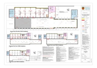
Ground Floor Plan New TGD B Compliance
1 : 200
Proposed First Floor TGDB Compliance 1 : 200
Second Floor Level TGD B Compliance
1 : 200
Third Floor Level TGD B Compliance
Building Regulations: Consultation between the Conservation architects, the planning
authority and the fire authority shall
take place, where possible at a pre-planning stage, in order to identify any interventions
required to satisfy the fire regulations. Fire safety design solutions should impact as little
as possible on the important spaces, elements and fabric of the Protected Structure, and
alterations which impact on important fabric should be readily reversible.
Planning Acts: All works which would materially affect the character of a Protected Structure
shall require planning permission, even where these works are necessary to comply with a
condition of a Fire Safety Certificate. It is therefore advisable that any planning application
includes details of the fire protection proposals for the building, so, that the local authorities
can assess the impact of those interventions on the Protected Structure. Should any
additional fire safety enhancement works be required which were not specifically included in a
grant of permission, then a further planning application may be necessary.
Principles
Because of the importance of preserving the architectural character of a Protected Structure,
imaginative compromises between active and passive fire protection measures will often
have to be made. A number of possible compensatory measures for works to RIAI
GUIDELINES FOR THE CONSERVATION OF BUILDINGS 30 existing buildings are outlined
in TGD B. Active provisions are those which come into action on detection of fire, such as fire
suppression systems, while passive provisions relate to the defence against fire provided by
the fabric and construction of a building,
such as floor and walls. Alternative approaches based on fire safety engineering may also
be employed to satisfy the requirements of the regulations
RIAI Guideline for the Conservation of Buildings (3RD EDITION © RIAI December 2010)
1.2.2.2 Travel distance
As indicated on Plans -45 m in two Directions -18m in One Dorection
Width of Escape Routes and Exits 1.2.4
1.2.5 Corridors
1.2.5.1 Protected corridors
All corridors in the building that are serving a means of escape are 60 m Fire
Protected as indicated on plans.
1.2.5.3 Sub-division of corridors
The Subdivision of the Corridor on the First Floor Level as it serves alternative
Escape Routes and the Corridor exceeds 12 m if it is not subdivided.
1.2.6 External Escape Routes
There are two External Escape Stairwells that serve the Building, the stairwells
are located on the North and South Sides of the building. As the floors they served
required
more than one Escape Route this was the only practicable alternative solution due
to floor to ceiling heighs and the incompatability and restrictions of the exisitng
Historic Building Fabric.
1.3 Design for Vertical Escape
1.3.2 Number of Escape Stairways
There are three Escape Stairwell, one inside the building and two External
Stairwells
1.3.4 Width of Escape Stairways
The Width of all the Stairwell both inside and outside the building are 1500mm
the reason for this
width is because of the mixed use of the building and the volume of people likely
to be using the staiwell if the use should change in the future.
1.3.4 Width of Escape Stairways
The Width of all the Stairwell both inside and outside the building are 1500mm
the reason for this
width is because of the mixed use of the building and the volume of people likely
to be using the stairwell if the use should change in the future.
1.3.6 Protection of Escape Stairways
All Stairwell are enclosed in Concrete Construction which has a class O Spread of
Flame
1.3.6.3 Exits from protected stairways
All Exits from the Stairwells are directed to a final Exit
1.3.8 Protected Lobbies and Corridors to Escape Stairways
There are two protected lobbies in the building on the First and Second floor built
of fire resisting construction.
1.3.9 External Escape Stairways
The Stairwell is built of Fire Resisting Construction
The doors are 30m Fire Resisting Construction
1.4.2 Protection of Escape Routes
All Building Elements that are meant to be fire resistant shall meet the provisions
in Tables A1 and A2 of Appendix A in TGD B
1.4.2.2 Fire resistance of doors
All proposed doors areto meet the provisions in Appendix B in TGD B.
Technical Guidance Document B Compliance Notes
1.4.2.3 Fire resistance of glazed elements
All windows in the fire resistant stairwellS are to meet the provisons in Appendix A, Table
A4 in TGD B
1.4.3 Doors on Escape Routes
All doors on escape routes are to open in the direction of escape.
1.4.3.5 Vision panels
Visions panels are provided on the proposed doors on the First floor that subdivides the
corridors.
1.4.4 Construction of Escape Stairways
All stairwells in the building are constructed of concrete which has a class 0 spread of
flame.
1.4.5 Height of Escape Routes
All escape Routes are above 2 m in Height
1.4.6 Floors of Escape Routes
All floors on escape rourte are of non slippery surface
1.4.7 Final Exits
All final Exits are to be dimensioned and sited and lead to a open space provided.
1.4.8 Lighting of Escape Routes
All lighting on escape routes shall be of the requitred lux levels for the spaces
.4.8.3 Emergency escape lighting shall be provided
To indicate escape routes and fire protection equipment
1.4.9 Lifts
The Lift propsoed for the building shall be appropriately sited and protected.
1.4.9.2 Fire protection of lift installations generally
The proposed lift shall be constructed in fire resistant concrete construction
1.4.13 Fire Safety Signs
Signs to indicate escape routes, including any doorways or exits which provide access to
the means of escape, shall be supplied , there are to be illuminated by natural daylight or
artificial daylight if necessary. They shall be clearly visible and distinguishable by
everyone.
1.4.14 Fire Detection and Alarm Systems
This Building shall be provided with a fire detection and alarm system to warn the
occupants of the existence of fire.
1.4.16 First-Aid Fire-Fighting Equipment
First-aid fire fighting equipment shall be provided in buildings to be used by the
occupants, with appropriate training and where it is safe to do so.
Section B2 Internal Fire Spread lining:
N/A
Section B3 Internal Fire Spread Structure:
1.1 Means of Escape Provisions for Different Purpose Groups
and Building Types
Purpose Group 5 Assembly Recreation
1.2 Design for Horizontal Escape
Number of Escape Routes and Exits
1.2.2
There are Eight Exits from the Ground Floor of the Building
There are 3 Escape Routes on the First Floor leading to a Final Exit
There are 3 Escape Routes on the Second Floor leading to a Final
Exit
There are 2 Escape Routes leading to a final Exit