SlideShare a Scribd company logo
1 of 7
Download to read offline
JC MACHINERY & TOOLS INC. Quality We Trust
_____________________________________________________________________
www.jc-tool.com info@jc-tool.com
Roof Waterproofing Membrane Welding Machine
JC-4200-WM
User Manual
JC MACHINERY & TOOLS INC. Quality We Trust
__________________________________________________________________
www.jc-tool.com info@jc-tool.com
1
Roof waterproofing membrane welding machine is high quality automatic hot air
welding machine; it is of new design and technology.
i. Applications
It can be applicable for overlap welding PVC、TPO、ECB、CSPE、EPDM and other
polymer film materials.
ii. Notice
1. Unplug the tools before opening it to avoid of being hurt by exposed wires or
component inside the machine with power
2. Incorrect use of it can cause fire and explosion hazard because of high
temperature, especially near combustible materials and explosive gases.
3. Don’t touch heater tube and nozzle when they are hot. They may cause burns.
Don’t point hot air flow in the direction of people or animals.
4. The voltage rating stated on the welder must correspond to line/mains voltage
(220V).
The drop cable / wire with protective earthed conductors can only be used.
5. To ensure operator safety and reliable operation of equipment, the power supply
must be installed power supply and leakage protection at the construction site.
6. It must be running at the correct use of manipulation of the operator, or they
may cause a fire or explosion caused by high temperature.
7. Don’t use welder in the water, or on a muddy construction site, to avoid flooding,
rain or moisture.
iii. Technical Parameters
Voltage 230 V
Frequency 50/60 Hz
power 4200 W
Temperature 50~620℃ (122~1148℉)
Welding speed <7.8 m/min
Welding width 40 mm
Size( LxWxH) 555x358x300 mm
Weight 34 kg
JC MACHINERY & TOOLS INC. Quality We Trust
__________________________________________________________________
www.jc-tool.com info@jc-tool.com
2
iv. Description
1. Pressure roller 14 Power cord 27 Belt wheel linkage
2. Drive roller 15
Temperature setting knob
(-)
28 Front wheel (left)
3 Hot air nozzle 16
Temperature setting knob
(+)
29 Guide wheel
4
Hot air blower fixed
slider
17 Speed setting knob(-) 30
Fixed axle of guide
wheel
5 Machine frame 18 Speed setting knob(+) 31
fixed plate of guide
wheel
6
Hot air blower guide
screw
19 LCD display screen 32
Limit groove plate of
guide wheel
7
Hot air blower fixed
set
20 Lift handle 33 Handle of guide wheel
8 Hot air blower 21 Clump weight (middle) 34 Front wheel (right)
9
Power wire of hot air
blower
22 Clump weight ( outer) 35
guide rail of hot air
blower
10 Guide bar 23 Belt wheel fixed screw 36 Baffle of micro switch
11 Handle 24 Rolling wheel 37 adjusting screw
12 Moving switch 25 Round belt 38
Position handle of hot
air blower
13 ON/OFF switch 26 Belt wheel 39 Casing cover
JC MACHINERY & TOOLS INC. Quality We Trust
__________________________________________________________________
www.jc-tool.com info@jc-tool.com
3
v. Controller Panel
● ON/OFF switch(13)is used for
open the main power of the welder
● Open ON/OFF switch (13),
LCD display is shown as Figure 1,
the hot air blower is under natural
wind without heating.
● Press the button (15) and
(16), the screen shows as Figure 2
and the hot air blower starts to heat until to
the setting temperature.
If press the bottoms (15) and (16) at the same time,
LCD display shows as Figure 1, the hot air blower is under natural wind without
heating.
● When the welding nozzle is at the right position, press the moving switch (12)
and the welder starts to move and weld. It will stop move if you press the moving
switch again.
● When the welder starts to move, the LCD display shows as Figure 3.
Figure1
Figure 2
Figure 3
Current temp.
Setting temp.
Current speed
Setting speed
Current temp.
Setting temp.
Setting temp.
Current temp.
Current speed
Setting speed
Setting speed
Current speed
JC MACHINERY & TOOLS INC. Quality We Trust
__________________________________________________________________
www.jc-tool.com info@jc-tool.com
4
VI. Welding Parameters Setting
VII. Positioning the Welder
1. Depress handle (11) to lift machine, move it to welding position (the edge of
upper film should keep in the same alignment with drive roller (2)), as shown in
figure 4.
2. Lift guide bar ( 10 ) to make front wheel (left) (28 ) off the ground,slide handle of
guide wheel (33) to right side until the right position of limit groove plate of guide
wheel (32), to keep the guide wheel (29) in the same alignment with the edge of
upper film.
1. Welding temperature:
Using bottoms Temperature setting knob+ and Temperature setting
knob- on the panel to set the required temperature. You can set the
temperature according to the welding materials and the ambient temperature. LCD
display will show the set temperature and the current actual temperature.
2. Welding speed:
Using bottoms Speed setting knob+ and Speed setting knob- on the
panel to set the required speed according to the welding temperature. LCD display
will show the set speed and the current actual speed.
3. The machine has a memory function parameters, namely when you use the welder
next time, the welder will automatically use the last set of parameters without having to
re-set parameters.
Upper film Down film
The edge of upper film
Figure 4
JC MACHINERY & TOOLS INC. Quality We Trust
__________________________________________________________________
www.jc-tool.com info@jc-tool.com
5
VII. Using Condition
1. The distance between hot air nozzle and ground should be shown as figure 5.(We
have adjusted the distance before leaving factory).
2. The distance between hot air nozzle and drive roller should be shown as figure 6.
(We have adjusted the distance before leaving factory). You can adjust hot air
nozzle adjusting screw (28) if the distance is not right.
VIII. Welding Process
1. Setting the welding parameters according to the data of welding test.
2. Please wait the actual temperature value reaching the setting value.
3. Positioning the welder
4. Lift the operating handle (38) to lower down the hot air nozzle (3) to close the
down ground, to place hot air nozzle to left in the right position. The machine
would start walking and welding automatically.
5. To observe the relative position of guide wheel (29). If it deviations from
position, you can adjust it by flipping the handle (11)
6. When the welder walks into the end of material, pull up the position handle of hot
air blower (38), move out of the hot air nozzle to right until stop, spin it up until
lock.
7. After finish the welding job, press the Temperature setting knob+
and Temperature setting knob- to make the hot air blower in a cold blowing
condition in order to cool the nozzle.
8. Last step is to off the power.
Figure 5 Figure 6
JC MACHINERY & TOOLS INC. Quality We Trust
__________________________________________________________________
www.jc-tool.com info@jc-tool.com
6
IX. Fault Diagnosis and Solved Ways
The fault performance Caused reasons Solved ways
Welder cannot walk
when hot air nozzle at
the right place
Micro switch is not
in right place
Move the hot air nozzle to the left and
put it in place, then loosen adjusting
screw (37);
Move baffle of micro switch (36) , to
place micro switch in the right position
The position between
hot air nozzle and drive
roller is not right
Adjust the fixed set of hot air blower
(7) ( by adjusting the screw under the
fixed set of hot air blower)
X. Routine Maintenance
Use steel brush to clean the hot air nozzle
Clean the air inlet at the back of the hot air blower

More Related Content

Similar to JC-4200 WM Roof Waterproofing Membrane Welder

MAHABIR - Double Side Planner Manual
MAHABIR - Double Side Planner ManualMAHABIR - Double Side Planner Manual
MAHABIR - Double Side Planner Manual
MahabirIndustries1
 
Jcb 516 40 telescopic handler service repair manual (from 2415604 to 2416000)
Jcb 516 40 telescopic handler service repair manual (from 2415604 to 2416000)Jcb 516 40 telescopic handler service repair manual (from 2415604 to 2416000)
Jcb 516 40 telescopic handler service repair manual (from 2415604 to 2416000)
fjjskedmme
 

Similar to JC-4200 WM Roof Waterproofing Membrane Welder (20)

Plastic Extrusion Welder
Plastic Extrusion WelderPlastic Extrusion Welder
Plastic Extrusion Welder
 
Lecture 2
Lecture 2Lecture 2
Lecture 2
 
P6 semi auto printer manual
P6 semi auto printer manualP6 semi auto printer manual
P6 semi auto printer manual
 
Diy cr7 fdm 3 d printer
Diy  cr7 fdm 3 d printerDiy  cr7 fdm 3 d printer
Diy cr7 fdm 3 d printer
 
P3 semi auto printer manual
P3 semi auto printer manualP3 semi auto printer manual
P3 semi auto printer manual
 
Hybrid Car
Hybrid CarHybrid Car
Hybrid Car
 
MAHABIR - Double Side Planner Manual
MAHABIR - Double Side Planner ManualMAHABIR - Double Side Planner Manual
MAHABIR - Double Side Planner Manual
 
DELTA HMI PROGRAMMING IN BANGLA
DELTA HMI PROGRAMMING IN BANGLADELTA HMI PROGRAMMING IN BANGLA
DELTA HMI PROGRAMMING IN BANGLA
 
Production automation lab
Production automation labProduction automation lab
Production automation lab
 
Viscometer model 900
Viscometer model 900Viscometer model 900
Viscometer model 900
 
Rt 40-rev-2
Rt 40-rev-2Rt 40-rev-2
Rt 40-rev-2
 
Yamaha Feeder Calibration Machine
Yamaha Feeder Calibration MachineYamaha Feeder Calibration Machine
Yamaha Feeder Calibration Machine
 
Effects_of_Misalignment.pdf
Effects_of_Misalignment.pdfEffects_of_Misalignment.pdf
Effects_of_Misalignment.pdf
 
Plasma 2012 AH Controller Manual
Plasma 2012 AH Controller ManualPlasma 2012 AH Controller Manual
Plasma 2012 AH Controller Manual
 
Xud9
Xud9Xud9
Xud9
 
IRJET- Modelling and Analysis of Two Wheeler Suspension System
IRJET- Modelling and Analysis of Two Wheeler Suspension SystemIRJET- Modelling and Analysis of Two Wheeler Suspension System
IRJET- Modelling and Analysis of Two Wheeler Suspension System
 
IRJET- All Reciprocating Automation in Hydraulic Press
IRJET-  	  All Reciprocating Automation in Hydraulic PressIRJET-  	  All Reciprocating Automation in Hydraulic Press
IRJET- All Reciprocating Automation in Hydraulic Press
 
Santec presentation on Heavy Duty Hydraulic presses
Santec presentation on  Heavy Duty  Hydraulic presses Santec presentation on  Heavy Duty  Hydraulic presses
Santec presentation on Heavy Duty Hydraulic presses
 
Panoura 18S Pan-Only Calibration and Alignment Quick Guide
Panoura 18S Pan-Only Calibration and Alignment Quick GuidePanoura 18S Pan-Only Calibration and Alignment Quick Guide
Panoura 18S Pan-Only Calibration and Alignment Quick Guide
 
Jcb 516 40 telescopic handler service repair manual (from 2415604 to 2416000)
Jcb 516 40 telescopic handler service repair manual (from 2415604 to 2416000)Jcb 516 40 telescopic handler service repair manual (from 2415604 to 2416000)
Jcb 516 40 telescopic handler service repair manual (from 2415604 to 2416000)
 

Recently uploaded

21P35A0312 Internship eccccccReport.docx
21P35A0312 Internship eccccccReport.docx21P35A0312 Internship eccccccReport.docx
21P35A0312 Internship eccccccReport.docx
rahulmanepalli02
 
Hospital management system project report.pdf
Hospital management system project report.pdfHospital management system project report.pdf
Hospital management system project report.pdf
Kamal Acharya
 
INTERRUPT CONTROLLER 8259 MICROPROCESSOR
INTERRUPT CONTROLLER 8259 MICROPROCESSORINTERRUPT CONTROLLER 8259 MICROPROCESSOR
INTERRUPT CONTROLLER 8259 MICROPROCESSOR
TanishkaHira1
 

Recently uploaded (20)

litvinenko_Henry_Intrusion_Hong-Kong_2024.pdf
litvinenko_Henry_Intrusion_Hong-Kong_2024.pdflitvinenko_Henry_Intrusion_Hong-Kong_2024.pdf
litvinenko_Henry_Intrusion_Hong-Kong_2024.pdf
 
Path loss model, OKUMURA Model, Hata Model
Path loss model, OKUMURA Model, Hata ModelPath loss model, OKUMURA Model, Hata Model
Path loss model, OKUMURA Model, Hata Model
 
Max. shear stress theory-Maximum Shear Stress Theory ​ Maximum Distortional ...
Max. shear stress theory-Maximum Shear Stress Theory ​  Maximum Distortional ...Max. shear stress theory-Maximum Shear Stress Theory ​  Maximum Distortional ...
Max. shear stress theory-Maximum Shear Stress Theory ​ Maximum Distortional ...
 
analog-vs-digital-communication (concept of analog and digital).pptx
analog-vs-digital-communication (concept of analog and digital).pptxanalog-vs-digital-communication (concept of analog and digital).pptx
analog-vs-digital-communication (concept of analog and digital).pptx
 
Danikor Product Catalog- Screw Feeder.pdf
Danikor Product Catalog- Screw Feeder.pdfDanikor Product Catalog- Screw Feeder.pdf
Danikor Product Catalog- Screw Feeder.pdf
 
21P35A0312 Internship eccccccReport.docx
21P35A0312 Internship eccccccReport.docx21P35A0312 Internship eccccccReport.docx
21P35A0312 Internship eccccccReport.docx
 
8th International Conference on Soft Computing, Mathematics and Control (SMC ...
8th International Conference on Soft Computing, Mathematics and Control (SMC ...8th International Conference on Soft Computing, Mathematics and Control (SMC ...
8th International Conference on Soft Computing, Mathematics and Control (SMC ...
 
Unsatisfied Bhabhi ℂall Girls Ahmedabad Book Esha 6378878445 Top Class ℂall G...
Unsatisfied Bhabhi ℂall Girls Ahmedabad Book Esha 6378878445 Top Class ℂall G...Unsatisfied Bhabhi ℂall Girls Ahmedabad Book Esha 6378878445 Top Class ℂall G...
Unsatisfied Bhabhi ℂall Girls Ahmedabad Book Esha 6378878445 Top Class ℂall G...
 
Hospital management system project report.pdf
Hospital management system project report.pdfHospital management system project report.pdf
Hospital management system project report.pdf
 
Overview of Transformation in Computer Graphics
Overview of Transformation in Computer GraphicsOverview of Transformation in Computer Graphics
Overview of Transformation in Computer Graphics
 
Adsorption (mass transfer operations 2) ppt
Adsorption (mass transfer operations 2) pptAdsorption (mass transfer operations 2) ppt
Adsorption (mass transfer operations 2) ppt
 
Independent Solar-Powered Electric Vehicle Charging Station
Independent Solar-Powered Electric Vehicle Charging StationIndependent Solar-Powered Electric Vehicle Charging Station
Independent Solar-Powered Electric Vehicle Charging Station
 
Computer Graphics Introduction To Curves
Computer Graphics Introduction To CurvesComputer Graphics Introduction To Curves
Computer Graphics Introduction To Curves
 
Working Principle of Echo Sounder and Doppler Effect.pdf
Working Principle of Echo Sounder and Doppler Effect.pdfWorking Principle of Echo Sounder and Doppler Effect.pdf
Working Principle of Echo Sounder and Doppler Effect.pdf
 
Fundamentals of Structure in C Programming
Fundamentals of Structure in C ProgrammingFundamentals of Structure in C Programming
Fundamentals of Structure in C Programming
 
HOA1&2 - Module 3 - PREHISTORCI ARCHITECTURE OF KERALA.pptx
HOA1&2 - Module 3 - PREHISTORCI ARCHITECTURE OF KERALA.pptxHOA1&2 - Module 3 - PREHISTORCI ARCHITECTURE OF KERALA.pptx
HOA1&2 - Module 3 - PREHISTORCI ARCHITECTURE OF KERALA.pptx
 
INTERRUPT CONTROLLER 8259 MICROPROCESSOR
INTERRUPT CONTROLLER 8259 MICROPROCESSORINTERRUPT CONTROLLER 8259 MICROPROCESSOR
INTERRUPT CONTROLLER 8259 MICROPROCESSOR
 
Lect.1: Getting Started (CS771: Machine Learning by Prof. Purushottam Kar, II...
Lect.1: Getting Started (CS771: Machine Learning by Prof. Purushottam Kar, II...Lect.1: Getting Started (CS771: Machine Learning by Prof. Purushottam Kar, II...
Lect.1: Getting Started (CS771: Machine Learning by Prof. Purushottam Kar, II...
 
Passive Air Cooling System and Solar Water Heater.ppt
Passive Air Cooling System and Solar Water Heater.pptPassive Air Cooling System and Solar Water Heater.ppt
Passive Air Cooling System and Solar Water Heater.ppt
 
5G and 6G refer to generations of mobile network technology, each representin...
5G and 6G refer to generations of mobile network technology, each representin...5G and 6G refer to generations of mobile network technology, each representin...
5G and 6G refer to generations of mobile network technology, each representin...
 

JC-4200 WM Roof Waterproofing Membrane Welder

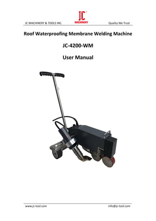
  • 1. JC MACHINERY & TOOLS INC. Quality We Trust _____________________________________________________________________ www.jc-tool.com info@jc-tool.com Roof Waterproofing Membrane Welding Machine JC-4200-WM User Manual
  • 2. JC MACHINERY & TOOLS INC. Quality We Trust __________________________________________________________________ www.jc-tool.com info@jc-tool.com 1 Roof waterproofing membrane welding machine is high quality automatic hot air welding machine; it is of new design and technology. i. Applications It can be applicable for overlap welding PVC、TPO、ECB、CSPE、EPDM and other polymer film materials. ii. Notice 1. Unplug the tools before opening it to avoid of being hurt by exposed wires or component inside the machine with power 2. Incorrect use of it can cause fire and explosion hazard because of high temperature, especially near combustible materials and explosive gases. 3. Don’t touch heater tube and nozzle when they are hot. They may cause burns. Don’t point hot air flow in the direction of people or animals. 4. The voltage rating stated on the welder must correspond to line/mains voltage (220V). The drop cable / wire with protective earthed conductors can only be used. 5. To ensure operator safety and reliable operation of equipment, the power supply must be installed power supply and leakage protection at the construction site. 6. It must be running at the correct use of manipulation of the operator, or they may cause a fire or explosion caused by high temperature. 7. Don’t use welder in the water, or on a muddy construction site, to avoid flooding, rain or moisture. iii. Technical Parameters Voltage 230 V Frequency 50/60 Hz power 4200 W Temperature 50~620℃ (122~1148℉) Welding speed <7.8 m/min Welding width 40 mm Size( LxWxH) 555x358x300 mm Weight 34 kg
  • 3. JC MACHINERY & TOOLS INC. Quality We Trust __________________________________________________________________ www.jc-tool.com info@jc-tool.com 2 iv. Description 1. Pressure roller 14 Power cord 27 Belt wheel linkage 2. Drive roller 15 Temperature setting knob (-) 28 Front wheel (left) 3 Hot air nozzle 16 Temperature setting knob (+) 29 Guide wheel 4 Hot air blower fixed slider 17 Speed setting knob(-) 30 Fixed axle of guide wheel 5 Machine frame 18 Speed setting knob(+) 31 fixed plate of guide wheel 6 Hot air blower guide screw 19 LCD display screen 32 Limit groove plate of guide wheel 7 Hot air blower fixed set 20 Lift handle 33 Handle of guide wheel 8 Hot air blower 21 Clump weight (middle) 34 Front wheel (right) 9 Power wire of hot air blower 22 Clump weight ( outer) 35 guide rail of hot air blower 10 Guide bar 23 Belt wheel fixed screw 36 Baffle of micro switch 11 Handle 24 Rolling wheel 37 adjusting screw 12 Moving switch 25 Round belt 38 Position handle of hot air blower 13 ON/OFF switch 26 Belt wheel 39 Casing cover
  • 4. JC MACHINERY & TOOLS INC. Quality We Trust __________________________________________________________________ www.jc-tool.com info@jc-tool.com 3 v. Controller Panel ● ON/OFF switch(13)is used for open the main power of the welder ● Open ON/OFF switch (13), LCD display is shown as Figure 1, the hot air blower is under natural wind without heating. ● Press the button (15) and (16), the screen shows as Figure 2 and the hot air blower starts to heat until to the setting temperature. If press the bottoms (15) and (16) at the same time, LCD display shows as Figure 1, the hot air blower is under natural wind without heating. ● When the welding nozzle is at the right position, press the moving switch (12) and the welder starts to move and weld. It will stop move if you press the moving switch again. ● When the welder starts to move, the LCD display shows as Figure 3. Figure1 Figure 2 Figure 3 Current temp. Setting temp. Current speed Setting speed Current temp. Setting temp. Setting temp. Current temp. Current speed Setting speed Setting speed Current speed
  • 5. JC MACHINERY & TOOLS INC. Quality We Trust __________________________________________________________________ www.jc-tool.com info@jc-tool.com 4 VI. Welding Parameters Setting VII. Positioning the Welder 1. Depress handle (11) to lift machine, move it to welding position (the edge of upper film should keep in the same alignment with drive roller (2)), as shown in figure 4. 2. Lift guide bar ( 10 ) to make front wheel (left) (28 ) off the ground,slide handle of guide wheel (33) to right side until the right position of limit groove plate of guide wheel (32), to keep the guide wheel (29) in the same alignment with the edge of upper film. 1. Welding temperature: Using bottoms Temperature setting knob+ and Temperature setting knob- on the panel to set the required temperature. You can set the temperature according to the welding materials and the ambient temperature. LCD display will show the set temperature and the current actual temperature. 2. Welding speed: Using bottoms Speed setting knob+ and Speed setting knob- on the panel to set the required speed according to the welding temperature. LCD display will show the set speed and the current actual speed. 3. The machine has a memory function parameters, namely when you use the welder next time, the welder will automatically use the last set of parameters without having to re-set parameters. Upper film Down film The edge of upper film Figure 4
  • 6. JC MACHINERY & TOOLS INC. Quality We Trust __________________________________________________________________ www.jc-tool.com info@jc-tool.com 5 VII. Using Condition 1. The distance between hot air nozzle and ground should be shown as figure 5.(We have adjusted the distance before leaving factory). 2. The distance between hot air nozzle and drive roller should be shown as figure 6. (We have adjusted the distance before leaving factory). You can adjust hot air nozzle adjusting screw (28) if the distance is not right. VIII. Welding Process 1. Setting the welding parameters according to the data of welding test. 2. Please wait the actual temperature value reaching the setting value. 3. Positioning the welder 4. Lift the operating handle (38) to lower down the hot air nozzle (3) to close the down ground, to place hot air nozzle to left in the right position. The machine would start walking and welding automatically. 5. To observe the relative position of guide wheel (29). If it deviations from position, you can adjust it by flipping the handle (11) 6. When the welder walks into the end of material, pull up the position handle of hot air blower (38), move out of the hot air nozzle to right until stop, spin it up until lock. 7. After finish the welding job, press the Temperature setting knob+ and Temperature setting knob- to make the hot air blower in a cold blowing condition in order to cool the nozzle. 8. Last step is to off the power. Figure 5 Figure 6
  • 7. JC MACHINERY & TOOLS INC. Quality We Trust __________________________________________________________________ www.jc-tool.com info@jc-tool.com 6 IX. Fault Diagnosis and Solved Ways The fault performance Caused reasons Solved ways Welder cannot walk when hot air nozzle at the right place Micro switch is not in right place Move the hot air nozzle to the left and put it in place, then loosen adjusting screw (37); Move baffle of micro switch (36) , to place micro switch in the right position The position between hot air nozzle and drive roller is not right Adjust the fixed set of hot air blower (7) ( by adjusting the screw under the fixed set of hot air blower) X. Routine Maintenance Use steel brush to clean the hot air nozzle Clean the air inlet at the back of the hot air blower