SlideShare a Scribd company logo
1 of 8
Download to read offline
Title: To prepare a Pocket of Aluminum by face Milling on CNC Milling machine
Location: CIM Center
Machining Capacity
MANUFACTURING PROCESSESS LAB – VI
Student’s Name: MUHAMMAD SHEHRYAR IMTIAZ Registration Number/Roll No. ME181056
Max. Marks: 25
A. Introduction
THE MILLING OPERATION
CNC stands for computer numerically controlled. As a milling technique, this means that a design
can be specified on a computer using CAD tools, and that a computer can handle the milling
process. And the program is able to specify the movements that the mill and table mustmake.
CNC milling is a specific form of computer numerical controlled (CNC) machining consisting of
both the drilling and cutting. Mill uses a rotating cylindrical cutting tool. However, the cutter in a
milling machine is able to move along multiple axes, and can create a variety of shapes, slots and
holes. In addition, the work-piece is often moved across the milling tool in different directions,
unlike the single axis motion of a drill.
INTRODUCTION OF THE MACHINE
In the machine, the labelled axes, X and Y designate horizontal movement of the work-piece
(forward-and-back and side-to-side on a flat plane). And Z represents vertical, or up-and-down
movement.
CNC milling machine also integrate a device for pumping cutting fluid to the cutting tool during
machining. This machine can be used to produce a wide range of components, and tooling costs
involved have continued to become more affordable day by day. It provides ideal solutions to
everything ranging from prototyping and short-run production of complex parts to the fabrication
of unique precision components.
MACHINABLE MATERIALS
Virtually every type of material that can be drilled or cut can be machined by a CNC mill, although
most of the work performed is done in metal. As with drilling and cutting, the proper machine tools
must be selected for each material in order to avert potential problems. The hardness of the work-
piece material, as well as the rotation of the cutting tool must all be factored before beginning the
machining process
To manufacture a Pocket of Aluminum by face Milling on CNC machine
Title: To prepare a Pocket of Aluminum by face Milling on CNC Milling machine
Location: CIM Center
G codes and M codes for CNC machine controls
G-code is a common name for the programming language that is used for NC and CNC machine
tools. It is defined in EIA RS-274-D. G-code is also the name of any word in a CNC programthat
begins with the letter G, and generally is a code telling the machine tool what type of action to
perform, such as:
âś“ Rapid move
âś“ Controlled feed moves in straight line or arc
âś“ Series of controlled feed moves that would result in a hole being drilled.
âś“ Change a pallet
âś“ Set tool information such as offset.
There are other codes; the type codes can be thought of like registers in a computer
âś“ X position
âś“ Y position
âś“ Z position
âś“ M code (another "action" register)
âś“ F feed rate
âś“ S spindle speed
âś“ N line number
âś“ R Radius
âś“ T Tool selection
âś“ I Arc data X axis
âś“ J Arc data Yaxis
G-code files are output by CAM software such as Smartcam, Gibbscam, Featurecam, Edgecam,
Mastercam, etc. G-code is also output by specialized CAD systems used to design printed circuit
boards. Such software must be customized for each type of machine tool that it will be used to
program.
G & M-Code programming language used in the CNC Machining Industry.
CNC G Codes
G00 - Positioning at rapid speed; Mill and Lathe
G01 - Linear interpolation (machining a straight line); Mill and Lathe
G02 - Circular interpolation clockwise (machining arcs); Mill and Lathe
Title: To prepare a Pocket of Aluminum by face Milling on CNC Milling machine
Location: CIM Center
G03 - Circular interpolation, counter clockwise; Mill and Lathe
G04 - Mill and Lathe, Dwell
G09 - Mill and Lathe, Exact stop
G10 - Setting offsets in the program; Mill and Lathe
G12 - Circular pocket milling, clockwise; Mill
G13 - Circular pocket milling, counterclockwise; Mill
G17 - X-Y plane for arc machining; Mill and Lathe with live tooling
G18 - Z-X plane for arc machining; Mill and Lathe with live tooling
G19 - Z-Y plane for arc machining; Mill and Lathe with live tooling
G20 - Inch units; Mill and Lathe
G21 - Metric units; Mill and Lathe
G27 - Reference return check; Mill and Lathe
G28 - Automatic return through reference point; Mill and Lathe
G29 - Move to location through reference point; Mill and Lathe (slightly different for each
machine)
G31 - Skip function; Mill and Lathe
G32 - Thread cutting; Lathe
G33 - Thread cutting; Mill
G40 - Cancel diameter offset; Mill. Cancel tool nose offset; Lathe
G41 - Cutter compensation left; Mill. Tool nose radius compensation left; Lathe
G42 - Cutter compensation right; Mill. Tool nose radius compensation right; Lathe
G43 - Tool length compensation; Mill
G44 - Tool length compensation cancel; Mill (sometimes G49)
G50 - Set coordinate system and maximum RPM; Lathe
G52 - Local coordinate system setting; Mill and Lathe
G53 - Machine coordinate system setting; Mill and Lathe
G54~G59 - Workpiece coordinate system settings #1 t0 #6; Mill and Lathe
G61 - Exact stop check; Mill and Lathe
G65 - Custom macro call; Mill and Lathe
G70 - Finish cycle; Lathe
G71 - Rough turning cycle; Lathe
G72 - Rough facing cycle; Lathe
G73 - Irregular rough turning cycle; Lathe
G73 - Chip break drilling cycle; Mill
G74 - Left hand tapping; Mill
G74 - Face grooving or chip break drilling; Lathe
G75 - OD groove pecking; Lathe
G76 - Fine boring cycle; Mill
G76 - Threading cycle; Lathe
G80 - Cancel cycles; Mill and Lathe
G81 - Drill cycle; Mill and Lathe
G82 - Drill cycle with dwell; Mill
G83 - Peck drilling cycle; Mill
G84 - Tapping cycle; Mill and Lathe
G85 - Bore in, bore out; Mill and Lathe
G86 - Bore in, rapid out; Mill and Lathe
Title: To prepare a Pocket of Aluminum by face Milling on CNC Milling machine
Location: CIM Center
G87 - Back boring cycle; Mill
G90 - Absolute programming
G91 - Incremental programming
G92 - Reposition origin point; Mill
G92 - Thread cutting cycle; Lathe
G94 - Per minute feed; Mill
G95 - Per revolution feed; Mill
G96 - Constant surface speed control; Lathe
G97 - Constant surface speed cancel
G98 - Per minute feed; Lathe
G99 - Per revolution feed; Lathe
CNC M Codes
M00 - Program stop; Mill and Lathe
M01 - Optional program stop; Lathe and Mill
M02 - Program end; Lathe and Mill
M03 - Spindle on clockwise; Lathe and Mill
M04 - Spindle on counterclockwise; Lathe and Mill
M05 - Spindle off; Lathe and Mill
M06 - Toolchange; Mill
M08 - Coolant on; Lathe and Mill
M09 - Coolant off; Lathe and Mill
M10 - Chuck or rotary table clamp; Lathe and Mill
M11 - Chuck or rotary table clamp off; Lathe and Mill
M19 - Orient spindle; Lathe and Mill
M30 - Program end, return to start; Lathe and Mill
M97 - Local sub-routine call; Lathe and Mill
M98 - Sub-program call; Lathe and Mill
M99 - End of sub program; Lathe and Mill
B. Programming
Write the program for the manufacturing of a Pocket of Aluminum by face Milling on CNC
Milling machine and also attach the drawing also.
Title: To prepare a Pocket of Aluminum by face Milling on CNC Milling machine
Location: CIM Center
C. Result
A Pocket of Aluminum by face Milling on CNC machine is prepared.
C. Lab Discussion
Q1) How many types of Face milling operations are there. Describe them briefly? [5]
Face milling:
In face milling, the axis of the cutter is perpendicular to the surface being milled, and machining is
performed by cutting edges on both the end and outside periphery of the cutter.
Types of face milling:
1. Conventional face milling:
In which the diameter of the cutter is greater than the work part width, so the cutter overhangs the
work on both sides.
2. Partial face milling:
Where the cutter overhangs the work on only one side.
3. End milling:
In which the cutter diameter is less than the work width, so a slot is cut into the part.
4. Profile milling:
A form of end milling in which the outside periphery of a flat part is cut.
5. Pocket milling:
Another form of end milling used to mill shallow pockets into flat parts.
6. Surface contouring:
In which a ball-nose cutter (rather than square end cutter) is fed back and forth across the work
along a curvilinear path at close intervals to create a three-dimensional surface form.
Q2) What is the difference between face mill and end mill cutters? [4]
Face milling cutters have a cutting edge on the end face and outer circle perpendicular to the arbor,
which are mainly used for milling planes. The cutting edge of the outer circle is the main cutting
edge, and the cutting edge of the end face plays the same role as the scraper. Face milling cutters
have shorter blades than sleeve end mills.
End milling is one of the most used milling cutters on CNC machine tools. Both the cylindrical
surface and the end surface of the end mill have cutting cutters. They can be cut simultaneously or
separately. Mainly used for plane milling, groove milling, step face milling and profiling milling.
Title: To prepare a Pocket of Aluminum by face Milling on CNC Milling machine
Location: CIM Center
End milling can be used as face milling. However, because the main declination angle is 90°, the
force of the tool is mainly radial force in addition to the main cutting force, which is easy to cause
deflection and deformation of the arbor, and it is also easy to cause vibration, which affects the
processing efficiency. Therefore, except for similar to the thin-bottom workpiece Except for special
reasons such as small axial force or occasional face milling, which is occasionally necessary to
reduce the variety of tool stocks, it is not recommended to use an end mill to machine flat surfaces
without steps.
Face milling cutter blades VS. end milling cutter tool head
Q3) In which operation do you think are more forces acting on the tool, Milling or Drilling,
even if machining is done with similar cutting parameters and materials? Why? [3]
In drilling you need axial thrust bearing while milling needs radial bearing.
Milling machines use an incredible amount of force. You won’t experience any vibrations or shaking
like you would with low-quality drills.
The results are often much cleaner, leaving hardly any metal debris behind. You’ll also notice that it’s
much quicker since it doesn’t have to go over the same area multiple times.
Milling machines allow you to rotate and move the bit while it’s cutting. Unlike a drill press that has
to go vertically when it’s cutting, you can rotate the bit on a milling machine for unique angles and
cuts. That’s why the milling shaft need to be fed with huge torque to beat the reverse torque from the
tool while it makes a cut.
Drills are much quicker to use from start to finish. You don’t have to adjust as many settings since
it’s very straightforward. Turn it on, place it where it needs to go, set the speed, place the correct bit,
and get to drilling. Not much force is acting on the tool bit since its made from materials which can
bear high shear stress from the workpiece.
Title: To prepare a Pocket of Aluminum by face Milling on CNC Milling machine
Location: CIM Center
Q4) It is said that the tool material should have a good “hot hardness”. Why this property is
important for tool material? (Explain in reference to tool wear) [3]
Hot Hardness:
Generally, hardness is measured at room temperature. But the term Hot hardness indicates that the
hardness at elevated temperature. We know that the hardness decreases as temperature increases. In
metal cutting, heat is generated during the process. The tool material must be able to maintain its
hardness, wear resistance and strength at such a high elevated temperature, which ranges nearly
600°C to 1800°C.
Q5) A face milling operation is used to machine 6.0mm from the top surface of a rectangular
piece of Aluminium 300 mm long by 125 mm wide in a single pass. The cutter follows a path
that is centred over the work piece. It has four teeth and is 150 mm in diameter. Cutting speed
= 2.8 m/s, and chip load = 0.27 mm/tooth. Determine
(a) The actual machining time (Tm) to make the pass across the surface. [8]
(b) The maximum metal removal rate (MRR) during cutting. [2]
(ATTACHMENT)
Title: To prepare a Pocket of Aluminum by face Milling on CNC Milling machine
Location: CIM Center

More Related Content

What's hot

Milling cutting data_calculator_2012 (1)
Milling cutting data_calculator_2012 (1)Milling cutting data_calculator_2012 (1)
Milling cutting data_calculator_2012 (1)Tom Jensby
 
Getting started iv2008
Getting started iv2008Getting started iv2008
Getting started iv2008Mrx Man
 
Parametric optimisation of cnc turning for al 7020 with rsm
Parametric optimisation of cnc turning for al 7020 with rsmParametric optimisation of cnc turning for al 7020 with rsm
Parametric optimisation of cnc turning for al 7020 with rsmDr. Bikram Jit Singh
 
Milling and dividing head
Milling and dividing headMilling and dividing head
Milling and dividing headdefault default
 
Manufacturing Technology -II Unit 1
Manufacturing Technology -II Unit 1Manufacturing Technology -II Unit 1
Manufacturing Technology -II Unit 1Ravi Sankar
 
CNC Machining of Face Cam on a Cylindrical Sector
CNC Machining of Face Cam on a Cylindrical SectorCNC Machining of Face Cam on a Cylindrical Sector
CNC Machining of Face Cam on a Cylindrical SectorIJERA Editor
 
HSMWORKS manual
HSMWORKS manualHSMWORKS manual
HSMWORKS manualendika55
 
Mm2013 milling tutorial
Mm2013 milling tutorialMm2013 milling tutorial
Mm2013 milling tutorialwongchukhang
 
Milling notes (man. sc. ii)
Milling notes (man. sc. ii)Milling notes (man. sc. ii)
Milling notes (man. sc. ii)Manoj Yadav
 
Milling machine-types-operations..etc..from L.NARAYANAN,M.E.,AP.MECH
Milling machine-types-operations..etc..from L.NARAYANAN,M.E.,AP.MECHMilling machine-types-operations..etc..from L.NARAYANAN,M.E.,AP.MECH
Milling machine-types-operations..etc..from L.NARAYANAN,M.E.,AP.MECHnaanmech123
 
Ch 9 shaper, planner, slotter
Ch 9 shaper, planner, slotterCh 9 shaper, planner, slotter
Ch 9 shaper, planner, slotterNandan Choudhary
 
Milling Machine
Milling MachineMilling Machine
Milling MachineDhyey Shukla
 
Milling machines
Milling machinesMilling machines
Milling machinesAvinash Navin
 
Milling machine-types-operations..etc..from L.NARAYANAN,M.E.,AP.MECH
Milling machine-types-operations..etc..from L.NARAYANAN,M.E.,AP.MECHMilling machine-types-operations..etc..from L.NARAYANAN,M.E.,AP.MECH
Milling machine-types-operations..etc..from L.NARAYANAN,M.E.,AP.MECHnaanmech123
 
Cncpresentation CNC lathe machine
Cncpresentation CNC lathe machineCncpresentation CNC lathe machine
Cncpresentation CNC lathe machineHaseeb Butt
 
Cnc cutting tools
Cnc cutting toolsCnc cutting tools
Cnc cutting toolsRakesh Raki
 
Presentation on different types of machine,spur gear making, single point cut...
Presentation on different types of machine,spur gear making, single point cut...Presentation on different types of machine,spur gear making, single point cut...
Presentation on different types of machine,spur gear making, single point cut...Reshad Ibn Momin
 

What's hot (20)

Milling cutting data_calculator_2012 (1)
Milling cutting data_calculator_2012 (1)Milling cutting data_calculator_2012 (1)
Milling cutting data_calculator_2012 (1)
 
Getting started iv2008
Getting started iv2008Getting started iv2008
Getting started iv2008
 
Parametric optimisation of cnc turning for al 7020 with rsm
Parametric optimisation of cnc turning for al 7020 with rsmParametric optimisation of cnc turning for al 7020 with rsm
Parametric optimisation of cnc turning for al 7020 with rsm
 
Milling and dividing head
Milling and dividing headMilling and dividing head
Milling and dividing head
 
Manufacturing Technology -II Unit 1
Manufacturing Technology -II Unit 1Manufacturing Technology -II Unit 1
Manufacturing Technology -II Unit 1
 
CNC Machining of Face Cam on a Cylindrical Sector
CNC Machining of Face Cam on a Cylindrical SectorCNC Machining of Face Cam on a Cylindrical Sector
CNC Machining of Face Cam on a Cylindrical Sector
 
HSMWORKS manual
HSMWORKS manualHSMWORKS manual
HSMWORKS manual
 
Ch 7 milling
Ch 7 millingCh 7 milling
Ch 7 milling
 
Mm2013 milling tutorial
Mm2013 milling tutorialMm2013 milling tutorial
Mm2013 milling tutorial
 
Milling notes (man. sc. ii)
Milling notes (man. sc. ii)Milling notes (man. sc. ii)
Milling notes (man. sc. ii)
 
Milling machine-types-operations..etc..from L.NARAYANAN,M.E.,AP.MECH
Milling machine-types-operations..etc..from L.NARAYANAN,M.E.,AP.MECHMilling machine-types-operations..etc..from L.NARAYANAN,M.E.,AP.MECH
Milling machine-types-operations..etc..from L.NARAYANAN,M.E.,AP.MECH
 
CIM Lab.pdf
CIM Lab.pdfCIM Lab.pdf
CIM Lab.pdf
 
Ch 9 shaper, planner, slotter
Ch 9 shaper, planner, slotterCh 9 shaper, planner, slotter
Ch 9 shaper, planner, slotter
 
Milling Machine
Milling MachineMilling Machine
Milling Machine
 
Milling machines
Milling machinesMilling machines
Milling machines
 
Milling machine-types-operations..etc..from L.NARAYANAN,M.E.,AP.MECH
Milling machine-types-operations..etc..from L.NARAYANAN,M.E.,AP.MECHMilling machine-types-operations..etc..from L.NARAYANAN,M.E.,AP.MECH
Milling machine-types-operations..etc..from L.NARAYANAN,M.E.,AP.MECH
 
Cncpresentation CNC lathe machine
Cncpresentation CNC lathe machineCncpresentation CNC lathe machine
Cncpresentation CNC lathe machine
 
Cnc cutting tools
Cnc cutting toolsCnc cutting tools
Cnc cutting tools
 
Milling
MillingMilling
Milling
 
Presentation on different types of machine,spur gear making, single point cut...
Presentation on different types of machine,spur gear making, single point cut...Presentation on different types of machine,spur gear making, single point cut...
Presentation on different types of machine,spur gear making, single point cut...
 

Similar to (me81056) face milling on cnc machine

Microproject on cnc milling machine
Microproject on cnc milling machineMicroproject on cnc milling machine
Microproject on cnc milling machineSumitSutar6
 
CNC-Mill-KV-Azlan-1.pdf
CNC-Mill-KV-Azlan-1.pdfCNC-Mill-KV-Azlan-1.pdf
CNC-Mill-KV-Azlan-1.pdfMohdAnuar39
 
drilling on cnc machine (me181056)
drilling on cnc machine (me181056)drilling on cnc machine (me181056)
drilling on cnc machine (me181056)ShehryarAwan3
 
internship presentation.pptx
internship presentation.pptxinternship presentation.pptx
internship presentation.pptxChinmaiKumar
 
CNC Maching.pptx
CNC Maching.pptxCNC Maching.pptx
CNC Maching.pptxstudyall1
 
introduction to cnc machines
 introduction to cnc machines introduction to cnc machines
introduction to cnc machinesSTAY CURIOUS
 
Cnc program writing
Cnc program writingCnc program writing
Cnc program writingmazharmustafa3
 
Introduction to CNC machines.pptx
Introduction to CNC machines.pptxIntroduction to CNC machines.pptx
Introduction to CNC machines.pptxDr.M BALA THEJA
 
Manufacturing Processes
Manufacturing ProcessesManufacturing Processes
Manufacturing ProcessesAnsar Mulla
 
Workshop Report.pdf
Workshop Report.pdfWorkshop Report.pdf
Workshop Report.pdfHogr kamal
 
MANUFACTURING SCIENCE II ppt on.pptx
MANUFACTURING SCIENCE II ppt on.pptxMANUFACTURING SCIENCE II ppt on.pptx
MANUFACTURING SCIENCE II ppt on.pptxArvindTiwari790920
 
Milling and gear cutting machines
Milling and gear cutting machinesMilling and gear cutting machines
Milling and gear cutting machinesArul R
 
MILLING PRESENTATION.pdf
MILLING PRESENTATION.pdfMILLING PRESENTATION.pdf
MILLING PRESENTATION.pdfSadishPuri
 
Cam presentation..
Cam presentation..Cam presentation..
Cam presentation..Akash Maurya
 
Computer aided manufacturing
Computer aided manufacturingComputer aided manufacturing
Computer aided manufacturingGulfaraz alam
 
BITAC industrial training report
BITAC industrial training reportBITAC industrial training report
BITAC industrial training reportShahrokh Ahmad
 
reprot on Industrial trainning at BITAC
reprot on Industrial trainning at BITACreprot on Industrial trainning at BITAC
reprot on Industrial trainning at BITACShahrokh Ahmad
 

Similar to (me81056) face milling on cnc machine (20)

Microproject on cnc milling machine
Microproject on cnc milling machineMicroproject on cnc milling machine
Microproject on cnc milling machine
 
CNC machine
CNC machineCNC machine
CNC machine
 
CNC-Mill-KV-Azlan-1.pdf
CNC-Mill-KV-Azlan-1.pdfCNC-Mill-KV-Azlan-1.pdf
CNC-Mill-KV-Azlan-1.pdf
 
drilling on cnc machine (me181056)
drilling on cnc machine (me181056)drilling on cnc machine (me181056)
drilling on cnc machine (me181056)
 
internship presentation.pptx
internship presentation.pptxinternship presentation.pptx
internship presentation.pptx
 
CNC Maching.pptx
CNC Maching.pptxCNC Maching.pptx
CNC Maching.pptx
 
introduction to cnc machines
 introduction to cnc machines introduction to cnc machines
introduction to cnc machines
 
Cnc program writing
Cnc program writingCnc program writing
Cnc program writing
 
Introduction to CNC machines.pptx
Introduction to CNC machines.pptxIntroduction to CNC machines.pptx
Introduction to CNC machines.pptx
 
Manufacturing Processes
Manufacturing ProcessesManufacturing Processes
Manufacturing Processes
 
Workshop Report.pdf
Workshop Report.pdfWorkshop Report.pdf
Workshop Report.pdf
 
MANUFACTURING SCIENCE II ppt on.pptx
MANUFACTURING SCIENCE II ppt on.pptxMANUFACTURING SCIENCE II ppt on.pptx
MANUFACTURING SCIENCE II ppt on.pptx
 
Milling and gear cutting machines
Milling and gear cutting machinesMilling and gear cutting machines
Milling and gear cutting machines
 
MILLING PRESENTATION.pdf
MILLING PRESENTATION.pdfMILLING PRESENTATION.pdf
MILLING PRESENTATION.pdf
 
Cam presentation..
Cam presentation..Cam presentation..
Cam presentation..
 
Computer aided manufacturing
Computer aided manufacturingComputer aided manufacturing
Computer aided manufacturing
 
CNC1.ppt
CNC1.pptCNC1.ppt
CNC1.ppt
 
BITAC industrial training report
BITAC industrial training reportBITAC industrial training report
BITAC industrial training report
 
reprot on Industrial trainning at BITAC
reprot on Industrial trainning at BITACreprot on Industrial trainning at BITAC
reprot on Industrial trainning at BITAC
 
CNC1.ppt
CNC1.pptCNC1.ppt
CNC1.ppt
 

Recently uploaded

An experimental study in using natural admixture as an alternative for chemic...
An experimental study in using natural admixture as an alternative for chemic...An experimental study in using natural admixture as an alternative for chemic...
An experimental study in using natural admixture as an alternative for chemic...Chandu841456
 
main PPT.pptx of girls hostel security using rfid
main PPT.pptx of girls hostel security using rfidmain PPT.pptx of girls hostel security using rfid
main PPT.pptx of girls hostel security using rfidNikhilNagaraju
 
Churning of Butter, Factors affecting .
Churning of Butter, Factors affecting  .Churning of Butter, Factors affecting  .
Churning of Butter, Factors affecting .Satyam Kumar
 
GDSC ASEB Gen AI study jams presentation
GDSC ASEB Gen AI study jams presentationGDSC ASEB Gen AI study jams presentation
GDSC ASEB Gen AI study jams presentationGDSCAESB
 
Architect Hassan Khalil Portfolio for 2024
Architect Hassan Khalil Portfolio for 2024Architect Hassan Khalil Portfolio for 2024
Architect Hassan Khalil Portfolio for 2024hassan khalil
 
Application of Residue Theorem to evaluate real integrations.pptx
Application of Residue Theorem to evaluate real integrations.pptxApplication of Residue Theorem to evaluate real integrations.pptx
Application of Residue Theorem to evaluate real integrations.pptx959SahilShah
 
Introduction to Machine Learning Unit-3 for II MECH
Introduction to Machine Learning Unit-3 for II MECHIntroduction to Machine Learning Unit-3 for II MECH
Introduction to Machine Learning Unit-3 for II MECHC Sai Kiran
 
Risk Assessment For Installation of Drainage Pipes.pdf
Risk Assessment For Installation of Drainage Pipes.pdfRisk Assessment For Installation of Drainage Pipes.pdf
Risk Assessment For Installation of Drainage Pipes.pdfROCENODodongVILLACER
 
🔝9953056974🔝!!-YOUNG call girls in Rajendra Nagar Escort rvice Shot 2000 nigh...
🔝9953056974🔝!!-YOUNG call girls in Rajendra Nagar Escort rvice Shot 2000 nigh...🔝9953056974🔝!!-YOUNG call girls in Rajendra Nagar Escort rvice Shot 2000 nigh...
🔝9953056974🔝!!-YOUNG call girls in Rajendra Nagar Escort rvice Shot 2000 nigh...9953056974 Low Rate Call Girls In Saket, Delhi NCR
 
pipeline in computer architecture design
pipeline in computer architecture  designpipeline in computer architecture  design
pipeline in computer architecture designssuser87fa0c1
 
Software and Systems Engineering Standards: Verification and Validation of Sy...
Software and Systems Engineering Standards: Verification and Validation of Sy...Software and Systems Engineering Standards: Verification and Validation of Sy...
Software and Systems Engineering Standards: Verification and Validation of Sy...VICTOR MAESTRE RAMIREZ
 
INFLUENCE OF NANOSILICA ON THE PROPERTIES OF CONCRETE
INFLUENCE OF NANOSILICA ON THE PROPERTIES OF CONCRETEINFLUENCE OF NANOSILICA ON THE PROPERTIES OF CONCRETE
INFLUENCE OF NANOSILICA ON THE PROPERTIES OF CONCRETEroselinkalist12
 
Call Girls Narol 7397865700 Independent Call Girls
Call Girls Narol 7397865700 Independent Call GirlsCall Girls Narol 7397865700 Independent Call Girls
Call Girls Narol 7397865700 Independent Call Girlsssuser7cb4ff
 
Biology for Computer Engineers Course Handout.pptx
Biology for Computer Engineers Course Handout.pptxBiology for Computer Engineers Course Handout.pptx
Biology for Computer Engineers Course Handout.pptxDeepakSakkari2
 
Sachpazis Costas: Geotechnical Engineering: A student's Perspective Introduction
Sachpazis Costas: Geotechnical Engineering: A student's Perspective IntroductionSachpazis Costas: Geotechnical Engineering: A student's Perspective Introduction
Sachpazis Costas: Geotechnical Engineering: A student's Perspective IntroductionDr.Costas Sachpazis
 
What are the advantages and disadvantages of membrane structures.pptx
What are the advantages and disadvantages of membrane structures.pptxWhat are the advantages and disadvantages of membrane structures.pptx
What are the advantages and disadvantages of membrane structures.pptxwendy cai
 
CCS355 Neural Network & Deep Learning Unit II Notes with Question bank .pdf
CCS355 Neural Network & Deep Learning Unit II Notes with Question bank .pdfCCS355 Neural Network & Deep Learning Unit II Notes with Question bank .pdf
CCS355 Neural Network & Deep Learning Unit II Notes with Question bank .pdfAsst.prof M.Gokilavani
 
Artificial-Intelligence-in-Electronics (K).pptx
Artificial-Intelligence-in-Electronics (K).pptxArtificial-Intelligence-in-Electronics (K).pptx
Artificial-Intelligence-in-Electronics (K).pptxbritheesh05
 

Recently uploaded (20)

An experimental study in using natural admixture as an alternative for chemic...
An experimental study in using natural admixture as an alternative for chemic...An experimental study in using natural admixture as an alternative for chemic...
An experimental study in using natural admixture as an alternative for chemic...
 
Call Us -/9953056974- Call Girls In Vikaspuri-/- Delhi NCR
Call Us -/9953056974- Call Girls In Vikaspuri-/- Delhi NCRCall Us -/9953056974- Call Girls In Vikaspuri-/- Delhi NCR
Call Us -/9953056974- Call Girls In Vikaspuri-/- Delhi NCR
 
main PPT.pptx of girls hostel security using rfid
main PPT.pptx of girls hostel security using rfidmain PPT.pptx of girls hostel security using rfid
main PPT.pptx of girls hostel security using rfid
 
Churning of Butter, Factors affecting .
Churning of Butter, Factors affecting  .Churning of Butter, Factors affecting  .
Churning of Butter, Factors affecting .
 
GDSC ASEB Gen AI study jams presentation
GDSC ASEB Gen AI study jams presentationGDSC ASEB Gen AI study jams presentation
GDSC ASEB Gen AI study jams presentation
 
Architect Hassan Khalil Portfolio for 2024
Architect Hassan Khalil Portfolio for 2024Architect Hassan Khalil Portfolio for 2024
Architect Hassan Khalil Portfolio for 2024
 
Application of Residue Theorem to evaluate real integrations.pptx
Application of Residue Theorem to evaluate real integrations.pptxApplication of Residue Theorem to evaluate real integrations.pptx
Application of Residue Theorem to evaluate real integrations.pptx
 
Introduction to Machine Learning Unit-3 for II MECH
Introduction to Machine Learning Unit-3 for II MECHIntroduction to Machine Learning Unit-3 for II MECH
Introduction to Machine Learning Unit-3 for II MECH
 
Risk Assessment For Installation of Drainage Pipes.pdf
Risk Assessment For Installation of Drainage Pipes.pdfRisk Assessment For Installation of Drainage Pipes.pdf
Risk Assessment For Installation of Drainage Pipes.pdf
 
🔝9953056974🔝!!-YOUNG call girls in Rajendra Nagar Escort rvice Shot 2000 nigh...
🔝9953056974🔝!!-YOUNG call girls in Rajendra Nagar Escort rvice Shot 2000 nigh...🔝9953056974🔝!!-YOUNG call girls in Rajendra Nagar Escort rvice Shot 2000 nigh...
🔝9953056974🔝!!-YOUNG call girls in Rajendra Nagar Escort rvice Shot 2000 nigh...
 
pipeline in computer architecture design
pipeline in computer architecture  designpipeline in computer architecture  design
pipeline in computer architecture design
 
Software and Systems Engineering Standards: Verification and Validation of Sy...
Software and Systems Engineering Standards: Verification and Validation of Sy...Software and Systems Engineering Standards: Verification and Validation of Sy...
Software and Systems Engineering Standards: Verification and Validation of Sy...
 
INFLUENCE OF NANOSILICA ON THE PROPERTIES OF CONCRETE
INFLUENCE OF NANOSILICA ON THE PROPERTIES OF CONCRETEINFLUENCE OF NANOSILICA ON THE PROPERTIES OF CONCRETE
INFLUENCE OF NANOSILICA ON THE PROPERTIES OF CONCRETE
 
Call Girls Narol 7397865700 Independent Call Girls
Call Girls Narol 7397865700 Independent Call GirlsCall Girls Narol 7397865700 Independent Call Girls
Call Girls Narol 7397865700 Independent Call Girls
 
Biology for Computer Engineers Course Handout.pptx
Biology for Computer Engineers Course Handout.pptxBiology for Computer Engineers Course Handout.pptx
Biology for Computer Engineers Course Handout.pptx
 
Exploring_Network_Security_with_JA3_by_Rakesh Seal.pptx
Exploring_Network_Security_with_JA3_by_Rakesh Seal.pptxExploring_Network_Security_with_JA3_by_Rakesh Seal.pptx
Exploring_Network_Security_with_JA3_by_Rakesh Seal.pptx
 
Sachpazis Costas: Geotechnical Engineering: A student's Perspective Introduction
Sachpazis Costas: Geotechnical Engineering: A student's Perspective IntroductionSachpazis Costas: Geotechnical Engineering: A student's Perspective Introduction
Sachpazis Costas: Geotechnical Engineering: A student's Perspective Introduction
 
What are the advantages and disadvantages of membrane structures.pptx
What are the advantages and disadvantages of membrane structures.pptxWhat are the advantages and disadvantages of membrane structures.pptx
What are the advantages and disadvantages of membrane structures.pptx
 
CCS355 Neural Network & Deep Learning Unit II Notes with Question bank .pdf
CCS355 Neural Network & Deep Learning Unit II Notes with Question bank .pdfCCS355 Neural Network & Deep Learning Unit II Notes with Question bank .pdf
CCS355 Neural Network & Deep Learning Unit II Notes with Question bank .pdf
 
Artificial-Intelligence-in-Electronics (K).pptx
Artificial-Intelligence-in-Electronics (K).pptxArtificial-Intelligence-in-Electronics (K).pptx
Artificial-Intelligence-in-Electronics (K).pptx
 

(me81056) face milling on cnc machine

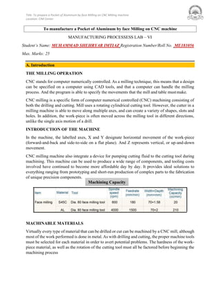
  • 1. Title: To prepare a Pocket of Aluminum by face Milling on CNC Milling machine Location: CIM Center Machining Capacity MANUFACTURING PROCESSESS LAB – VI Student’s Name: MUHAMMAD SHEHRYAR IMTIAZ Registration Number/Roll No. ME181056 Max. Marks: 25 A. Introduction THE MILLING OPERATION CNC stands for computer numerically controlled. As a milling technique, this means that a design can be specified on a computer using CAD tools, and that a computer can handle the milling process. And the program is able to specify the movements that the mill and table mustmake. CNC milling is a specific form of computer numerical controlled (CNC) machining consisting of both the drilling and cutting. Mill uses a rotating cylindrical cutting tool. However, the cutter in a milling machine is able to move along multiple axes, and can create a variety of shapes, slots and holes. In addition, the work-piece is often moved across the milling tool in different directions, unlike the single axis motion of a drill. INTRODUCTION OF THE MACHINE In the machine, the labelled axes, X and Y designate horizontal movement of the work-piece (forward-and-back and side-to-side on a flat plane). And Z represents vertical, or up-and-down movement. CNC milling machine also integrate a device for pumping cutting fluid to the cutting tool during machining. This machine can be used to produce a wide range of components, and tooling costs involved have continued to become more affordable day by day. It provides ideal solutions to everything ranging from prototyping and short-run production of complex parts to the fabrication of unique precision components. MACHINABLE MATERIALS Virtually every type of material that can be drilled or cut can be machined by a CNC mill, although most of the work performed is done in metal. As with drilling and cutting, the proper machine tools must be selected for each material in order to avert potential problems. The hardness of the work- piece material, as well as the rotation of the cutting tool must all be factored before beginning the machining process To manufacture a Pocket of Aluminum by face Milling on CNC machine
  • 2. Title: To prepare a Pocket of Aluminum by face Milling on CNC Milling machine Location: CIM Center G codes and M codes for CNC machine controls G-code is a common name for the programming language that is used for NC and CNC machine tools. It is defined in EIA RS-274-D. G-code is also the name of any word in a CNC programthat begins with the letter G, and generally is a code telling the machine tool what type of action to perform, such as: âś“ Rapid move âś“ Controlled feed moves in straight line or arc âś“ Series of controlled feed moves that would result in a hole being drilled. âś“ Change a pallet âś“ Set tool information such as offset. There are other codes; the type codes can be thought of like registers in a computer âś“ X position âś“ Y position âś“ Z position âś“ M code (another "action" register) âś“ F feed rate âś“ S spindle speed âś“ N line number âś“ R Radius âś“ T Tool selection âś“ I Arc data X axis âś“ J Arc data Yaxis G-code files are output by CAM software such as Smartcam, Gibbscam, Featurecam, Edgecam, Mastercam, etc. G-code is also output by specialized CAD systems used to design printed circuit boards. Such software must be customized for each type of machine tool that it will be used to program. G & M-Code programming language used in the CNC Machining Industry. CNC G Codes G00 - Positioning at rapid speed; Mill and Lathe G01 - Linear interpolation (machining a straight line); Mill and Lathe G02 - Circular interpolation clockwise (machining arcs); Mill and Lathe
  • 3. Title: To prepare a Pocket of Aluminum by face Milling on CNC Milling machine Location: CIM Center G03 - Circular interpolation, counter clockwise; Mill and Lathe G04 - Mill and Lathe, Dwell G09 - Mill and Lathe, Exact stop G10 - Setting offsets in the program; Mill and Lathe G12 - Circular pocket milling, clockwise; Mill G13 - Circular pocket milling, counterclockwise; Mill G17 - X-Y plane for arc machining; Mill and Lathe with live tooling G18 - Z-X plane for arc machining; Mill and Lathe with live tooling G19 - Z-Y plane for arc machining; Mill and Lathe with live tooling G20 - Inch units; Mill and Lathe G21 - Metric units; Mill and Lathe G27 - Reference return check; Mill and Lathe G28 - Automatic return through reference point; Mill and Lathe G29 - Move to location through reference point; Mill and Lathe (slightly different for each machine) G31 - Skip function; Mill and Lathe G32 - Thread cutting; Lathe G33 - Thread cutting; Mill G40 - Cancel diameter offset; Mill. Cancel tool nose offset; Lathe G41 - Cutter compensation left; Mill. Tool nose radius compensation left; Lathe G42 - Cutter compensation right; Mill. Tool nose radius compensation right; Lathe G43 - Tool length compensation; Mill G44 - Tool length compensation cancel; Mill (sometimes G49) G50 - Set coordinate system and maximum RPM; Lathe G52 - Local coordinate system setting; Mill and Lathe G53 - Machine coordinate system setting; Mill and Lathe G54~G59 - Workpiece coordinate system settings #1 t0 #6; Mill and Lathe G61 - Exact stop check; Mill and Lathe G65 - Custom macro call; Mill and Lathe G70 - Finish cycle; Lathe G71 - Rough turning cycle; Lathe G72 - Rough facing cycle; Lathe G73 - Irregular rough turning cycle; Lathe G73 - Chip break drilling cycle; Mill G74 - Left hand tapping; Mill G74 - Face grooving or chip break drilling; Lathe G75 - OD groove pecking; Lathe G76 - Fine boring cycle; Mill G76 - Threading cycle; Lathe G80 - Cancel cycles; Mill and Lathe G81 - Drill cycle; Mill and Lathe G82 - Drill cycle with dwell; Mill G83 - Peck drilling cycle; Mill G84 - Tapping cycle; Mill and Lathe G85 - Bore in, bore out; Mill and Lathe G86 - Bore in, rapid out; Mill and Lathe
  • 4. Title: To prepare a Pocket of Aluminum by face Milling on CNC Milling machine Location: CIM Center G87 - Back boring cycle; Mill G90 - Absolute programming G91 - Incremental programming G92 - Reposition origin point; Mill G92 - Thread cutting cycle; Lathe G94 - Per minute feed; Mill G95 - Per revolution feed; Mill G96 - Constant surface speed control; Lathe G97 - Constant surface speed cancel G98 - Per minute feed; Lathe G99 - Per revolution feed; Lathe CNC M Codes M00 - Program stop; Mill and Lathe M01 - Optional program stop; Lathe and Mill M02 - Program end; Lathe and Mill M03 - Spindle on clockwise; Lathe and Mill M04 - Spindle on counterclockwise; Lathe and Mill M05 - Spindle off; Lathe and Mill M06 - Toolchange; Mill M08 - Coolant on; Lathe and Mill M09 - Coolant off; Lathe and Mill M10 - Chuck or rotary table clamp; Lathe and Mill M11 - Chuck or rotary table clamp off; Lathe and Mill M19 - Orient spindle; Lathe and Mill M30 - Program end, return to start; Lathe and Mill M97 - Local sub-routine call; Lathe and Mill M98 - Sub-program call; Lathe and Mill M99 - End of sub program; Lathe and Mill B. Programming Write the program for the manufacturing of a Pocket of Aluminum by face Milling on CNC Milling machine and also attach the drawing also.
  • 5. Title: To prepare a Pocket of Aluminum by face Milling on CNC Milling machine Location: CIM Center C. Result A Pocket of Aluminum by face Milling on CNC machine is prepared. C. Lab Discussion Q1) How many types of Face milling operations are there. Describe them briefly? [5] Face milling: In face milling, the axis of the cutter is perpendicular to the surface being milled, and machining is performed by cutting edges on both the end and outside periphery of the cutter. Types of face milling: 1. Conventional face milling: In which the diameter of the cutter is greater than the work part width, so the cutter overhangs the work on both sides. 2. Partial face milling: Where the cutter overhangs the work on only one side. 3. End milling: In which the cutter diameter is less than the work width, so a slot is cut into the part. 4. Profile milling: A form of end milling in which the outside periphery of a flat part is cut. 5. Pocket milling: Another form of end milling used to mill shallow pockets into flat parts. 6. Surface contouring: In which a ball-nose cutter (rather than square end cutter) is fed back and forth across the work along a curvilinear path at close intervals to create a three-dimensional surface form. Q2) What is the difference between face mill and end mill cutters? [4] Face milling cutters have a cutting edge on the end face and outer circle perpendicular to the arbor, which are mainly used for milling planes. The cutting edge of the outer circle is the main cutting edge, and the cutting edge of the end face plays the same role as the scraper. Face milling cutters have shorter blades than sleeve end mills. End milling is one of the most used milling cutters on CNC machine tools. Both the cylindrical surface and the end surface of the end mill have cutting cutters. They can be cut simultaneously or separately. Mainly used for plane milling, groove milling, step face milling and profiling milling.
  • 6. Title: To prepare a Pocket of Aluminum by face Milling on CNC Milling machine Location: CIM Center End milling can be used as face milling. However, because the main declination angle is 90°, the force of the tool is mainly radial force in addition to the main cutting force, which is easy to cause deflection and deformation of the arbor, and it is also easy to cause vibration, which affects the processing efficiency. Therefore, except for similar to the thin-bottom workpiece Except for special reasons such as small axial force or occasional face milling, which is occasionally necessary to reduce the variety of tool stocks, it is not recommended to use an end mill to machine flat surfaces without steps. Face milling cutter blades VS. end milling cutter tool head Q3) In which operation do you think are more forces acting on the tool, Milling or Drilling, even if machining is done with similar cutting parameters and materials? Why? [3] In drilling you need axial thrust bearing while milling needs radial bearing. Milling machines use an incredible amount of force. You won’t experience any vibrations or shaking like you would with low-quality drills. The results are often much cleaner, leaving hardly any metal debris behind. You’ll also notice that it’s much quicker since it doesn’t have to go over the same area multiple times. Milling machines allow you to rotate and move the bit while it’s cutting. Unlike a drill press that has to go vertically when it’s cutting, you can rotate the bit on a milling machine for unique angles and cuts. That’s why the milling shaft need to be fed with huge torque to beat the reverse torque from the tool while it makes a cut. Drills are much quicker to use from start to finish. You don’t have to adjust as many settings since it’s very straightforward. Turn it on, place it where it needs to go, set the speed, place the correct bit, and get to drilling. Not much force is acting on the tool bit since its made from materials which can bear high shear stress from the workpiece.
  • 7. Title: To prepare a Pocket of Aluminum by face Milling on CNC Milling machine Location: CIM Center Q4) It is said that the tool material should have a good “hot hardness”. Why this property is important for tool material? (Explain in reference to tool wear) [3] Hot Hardness: Generally, hardness is measured at room temperature. But the term Hot hardness indicates that the hardness at elevated temperature. We know that the hardness decreases as temperature increases. In metal cutting, heat is generated during the process. The tool material must be able to maintain its hardness, wear resistance and strength at such a high elevated temperature, which ranges nearly 600°C to 1800°C. Q5) A face milling operation is used to machine 6.0mm from the top surface of a rectangular piece of Aluminium 300 mm long by 125 mm wide in a single pass. The cutter follows a path that is centred over the work piece. It has four teeth and is 150 mm in diameter. Cutting speed = 2.8 m/s, and chip load = 0.27 mm/tooth. Determine (a) The actual machining time (Tm) to make the pass across the surface. [8] (b) The maximum metal removal rate (MRR) during cutting. [2] (ATTACHMENT)
  • 8. Title: To prepare a Pocket of Aluminum by face Milling on CNC Milling machine Location: CIM Center