Muzaffarpur Escorts Service Girl ^ 9332606886, WhatsApp Anytime Muzaffarpur
DocScanner Nov 3, 2022 1-55 PM.docx
1. .irni En£ifieer
^n
^ Lah Jnstniction Manual
Geotechnical Engineering Lab Instruction Manual
1. SPECIFIC GRAVITY
PV Aim: To determine the specific gravity of a coarse grained soil sample by Pycnometer method.
Theory, Spee.He gravity . •™ spe.ifc W»™' ’P“ife
^i,y. significance and uses.
Apparatus
• Pycnometer with a conical cap screwed at its top
• Balance, sensitive to 0.2 g
• Wasli bottle with deaired, distilled water
• Glass rod, about 150 mm and 3 mm diameter
• Thermometer with 0 - 50°C range and accurate to 1°C.
• Thermostatically controlled oven.
Procedure
• Clean the Pycnometer, and dry it. Find the mass of the Pycnometer with its cap and washer, accurate to 1.0
g (Mj).
• Introduce about 400 g of oven dried coarse grained soil in to the Pycnometer. Record the mass of the
Pycnometer with its cap and washer along with the soil (M2).
• Fill the Pycnometer with distilled water to half its height, and mix it thoroughly with the soil using the glass
lud. Keep the entire system aside for about 4 hrs. At the end of this period, fill the Pycnometer with water
up to the top of the conical cap. Dry the Pycnometer from outside and record its mass (M3).
• Clean the Pycnometer thoroughly. Fill it with distilled water up to the top of conical cap. Dry the Pycnometer
from outside and record its mass to the nearest 0.2 g (M4).
• Repeat the steps (2) and (3) thrice.
• Calculate the specific gravity of the soil at the room temperature as well as at 27°C.
Results and discussions:
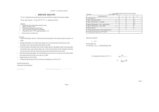
Observations and Calculations
Soil type: Lab. Temp. = T°C =
Determination No. 1 2 3 1
1. Pycnometer No.
2. Mass of Pycnometer (Mi) g —
3. Mass of (Pycnometer + soil) (M2) g —
4. Mass of (Pycnometer + soil + water) (M3) g 1
5. Mass of (Pycnometer + water) (M4) g
6. Specific gravity
7. Average specific gravity at lab temperature (GT)
8. Average specific gravity at 27°C (G27)
Specimen calculations
i) GT =
Relevant BIS Code:
IS: 2720 (Part 3 / Sec. 1)- 1980 (Reaffirmed 1987).
.............................
Contd..........
ii) Average specific gravity at 27°C = G
Contd ......
2. (n’otcc/iniai/ En^inecnn^ /.<") Instruction A’'"/""/
3
4
|B| Ail„:ro determine (he specific gravity of a fine-grained soil sample by density bottle | method.
/Apparatus
• Density bottle of approximately 50 ml capacity with stopper.
• A vacuum pump
• A vacuum desiccator
• A balance, sensitive to 0.001 g
• Wash bottle with deaired, distilled water
• Rubber tubing to connect the vacuum pump and the desiccator
• A thermometer with 0 - 50°C range and accurate to 1°C.
• A desiccator containing anhydious silica gel.
• Thermostatically controlled oven.
Procedure
• Clean and dr)' the density bottle with stopper a( 105°C to 110°C. Cool it in a desicuatur and determine its mass
to the nearest 0.001 g (M)).
• Take about 10 g of oven dried fine-grained soil and transfer it to the density bottle directly from the desiccator
in which it has been cooled. Record the mass of the density bottle with stopper and the soil to the nearest 0.001
g (M2).
• Add de-aired, distilled water to the density bottle such that the soil is just covered with waler. Plaue llic buttle
containing the soil and water without stopper in a vacuum desiccator and evacuate gradually. Allow the bottle
to remain in the desiccator for at least 1 hour until no further loss of air is apparent
• Release the vacuum. Take the bottle out of desiccator and fill it up to the calibrated mark with de-aiied, distilled
water.
• Wipe dry the outside of the bottle. Record the mass of the stoppered bottle containing the soil and water 10 the
nearest 0.001 g (M3).
• Clean the bottle thoroughly. Fill it with de-aired, distilled water up to the calibrated mark. Wipe dry the outside
of the bottle. Record the mass of the stoppered bottle with water to the nearest 0 001 g (M4).
• Repeat the steps (2) to (5) twice.
• Calculate the specific gravity of the soil sample at the room temperature and at 27U
C.
Note: If any liquid other than de-airen, distilled water is used to conduct the test, then calculate the specific gravity
of the soil with respect to distilled water using the following equation.
Gj= 01
---------------------------------- —-------------------- (3)
Geotechnical Engineering Lab Instruction Manual
Results and discussions:
................................................................................................................................................................
Observations and Calculations
Soil type Lab. Temp. = T°C = Liquid used in the test:
Determination No. 1 2 3
Density bottle No.
Mass of Density bottle (Mi) g
Mass of (Density bottle + soil) (M2)
Mass of (Density bottle + soil + liquid) (M3) g
Mass of (Density bottle +liquid) (M4)
Specific gravity with respect to test liquid (Gi)
Average specific gravity with respect to test liquid at lab
temperature (Gi)av
Average specific gravity with respect to water at lab temperature
(G3V)T
Average specific gravity at 27°C (G27)
Note: Calculate the average of the two determinations and report it to the nearest 0.01. If the two results differ by
more than 0.03, repeat the tests.
Specimen calculations
ii) Specific gravity with respect to water at room temperature = GT= GTL X Specific gravity of test
liquid =
iii) Average specific gravity at 27°C = G = <7 =
27 T (G nnzer
Relevant BIS Code:
IS: 2720 (Part 3 / Sec. 1) - 1980 (Reaffirmed 1987)
where GL = Specific gravity of the liquid used at lab temperature.
Contcl .
i)GTL = (M2-M,)
-M4)
3. Geotechnical Engineering IMU
Geotechnical Engineering Lab Instruction Manual
4
,rin_ _rav;tv ofa fine-grained soil sample by density bottle (B| Aj,n:To determine (he
specific gravity oi a im^ y
method.
-'’Dcmi^bottlc of approximately 50 ml capacity with stopper.
• A vacuum pump
• A vacuum desiccator
• A balance, sensitive to 0.001 g
• Wash bottle with dcaired, distilled water
-Rubber tubing to connect the vacuum pump and the desiccator .A ihcrmomctcr with 0 - 50°C range and
accurate to !0
C.
-A desiccator containing anhydrous silica gel.
• Thermostatically controlled oven.
.clean and dry (he density bottle with stopper at 105°C to 110"C. Cool it in a desuxiitur and dclerminc its mass
to the nearest 0.001 g(Mi).
• Take about 10 g of oven dried fine-grained soil and transfer it to the density bottle directly from the desiccator
in which it has been cooled. Record the mass of the density bottle with stopper and the soil to the nearest
0.001 g (M2).
• Add <lc-aircd, distilled water to the density bottle such that the soil is just covered with water. Plaue the buttle
containing the soil and water without stopper in a vacuum desiccator and evacuate gradually. Allow the bottle
to remain in the desiccator for nt least 1 hour until no further loss of air is apparent.
• Release the vacuum. Take the bottle out of desiccator and fill it up 10 the calibrated muik with de-türed,
distilled wnter.
• Wipe dry the outside of lhe bottle. Record the mass of the stoppered hottie confining the soil and waler to the
nearest 0.001 g (Mj).
-Clean the bottle thoroughly. Fill it with dc-airc<l, ilislillcil waler up to the calibrated mark. Wipe dry the outside
of the hottie. Record the mass of the stoppered bottle with water to the nc;irest 0 001 g (M.|).
• Repeat the steps (2) to (5) twice.
• Calculate the specific gravity ofthc soil sample at the room temperature and at 27V
C
If any liquid oilier than(lc-aire(i, distilled water is used (0 conduct the test, then calculate the specific
gravity ot the soil with respect to distilled waiter using the following equation.
Gt =
(M2-MU
H^TK?y Gl
--------------------------------------------------- (3)
Results and discussions:
Observations and Calculations
Soil type Lab. Temp. = T°C = Liquid used in the test:
Determination No. 1 2 3
Density bottle No.
Mass of Density bottle (Mi) g
Mass of (Density bottle + soil) (M>) g
Mass of (Density bottle + soil + liquid) (Mj) g
Mass of (Density bottle ^liquid) (M4) g
Specific gravity with respect to lest liquid (Gi)
Average specific gravity with respect to test liquid at lab temperature
(Gi)av
Average specific gravity with respect to water at lab temperature
(Ga%}r
Average specific gravity at 27"C (G27)
Note: Calculate the average of the two determinations and report it to the nearest 0.01. If the two results differ by
more than 0.03, repeat the tests.
Specimen calculations
i) Gri——_
(MJ-MJ-CMJ -MJ
ii) Specific gravity with respect to water at room temperature = Gr= GTL X Specific gravity of lest
liquid -
iii) Average specific gravity at 27°C = G =(j ^,,er
=
27
Relevant BIS Code:
IS: 2720 (Part 3/See. 1) - 1980 (Reaffirmed 1987)
where 6, ■= Specific gravity of the liquid used at lab temperature.
Contd .
4. Geotechnical Engineering Lab Instruction Manual
2. SIEVE ANALYSTS
• „fthe civcn soil by dry sieving. ,;„aze distribution of the give
Aim: To determine thegra ..
f soils' IS system, MIT system, Differentiation: clay Theory: Particle size
classification characteristic sizes, well graded
size fraction and clays; Part
::: characteristics.
and poorly graded soils; gradation eh.
425 micron, 300 micron, 212
micron, 150 micron, 106 micron’
2. Brushes to clean the sieves
3, Mechanical sieve shaker
6. Thermostatically controlled hot air oven
Procedure .
1 Oven dry the given soil sample passing 4.75 mm IS sieve.
2. Take 200 g of oven dried soil sample. Mix the sample with distilled water to form a slurry and allow it for soaking.
3. Wash the soaked soil sample through 75 micron sieve until the water passing thiough the sieve is substantially
clear.
4. Dry the fraction of the soil retained on 75 micron sieve in oven.
5. Arrange the remaining sieves one above the other such that 2mm sieve is at the top and 75 micron sieve is at the
bottom. Place a cover at the top and receiver at the bottom.
6. Fix the set of sieves to the mechanical sieve shaker. Operate the sieve shaker for a minimum of 10 minutes.
7. Carefully collect and record the mass of the soil fraction retained on each sieve and also in the receiver.
8. Calculate the cumulative mass of soil traction retained on each sieve. Calculate the percentage finer.
9. Plot a graph of percentage finer (along y-axis) Vs equivalent particle diameter in mm
10. Re~vZ ::::: the
P*°ttCd
P0
*. . e fractions from the
graph. ° d
’ percenta
ge
silt and percentage clay size
11. Record D]0, D30 and D60 from the graph
12. Calculate coefficient of curvature (Cd wl ,
13. Classify the soil based on gradation ‘ fficient of
uniformity (Cu).
Geotechnical Engineering Lab Instruction Manual
Observation and Calculations
......................
Total mass of soil taken for analysis = M =
Specimen Calculations
Corrected mass retained = m = m' x
M'
From the graph
1) The given soil is grained.
2) (i) % sand = (ii) % silt = (iii) % clay size =
3) (i) Dio = (ii) D30 = (iii) Deo =
4) (i) Coefficient of uniformity = Cu = D(so / Dm =
.. (D )2
(ii) Coefficient of curvature = Cc = 30
=
D
>0XD
60
5) Particle size and gradation classification of the given soil:
(reason: )
Results anil Discussions:
jnull, 600 liiicron,
75 micron.
4. Balance
IS Sieve Practical
size D, mm
Mass retained
m',g
Corrected mass
retained
m,g
0/ /o
retained
Cumulative
% retained
% finer (N)
4.75mm 4.75mm
2mm 2 mm
1 mm 1mm
600 micron 0.6mm
425 micron 0.425 mm
300 micron 0.3mm
212 micron 0.212mm
150 micron 0.15mm
106 micron 0.106mm
75 micron 0.075mm
Receiver 0.075 mm
M'=
1
5. Geotechnical Engineering Lab Instruction
3. HYDROMETER ANALYSIS
... sjzc and clay size fractions of the given soil by
Alm:T« <.«™». r«'"'*si
"siXC
'- ' '
hydrometer analysis.
• - Principle and assumptions made; Hydrometer analysis;
Theory: Sedimentation analys-s^^^ hydromctcr readings.
Calibration ofhydromete ’
Apparatus
j jiu-ee 1000 ml capacity n
icasuringjars
2. Hydrometer
3. Mechanical stirrer
xx—p
_ha,c and
—“
6. Thermostatically controlled hot air oven
7. Stop watch
Procedure
1. Calibrate the hydrometer to be used in lhe test,
2. Determine the meniscus correction. .
3. Take about 50 g of oven dried soil sample passing 75 |i IS sieve.
4 Subject the soil to pre-treatment to remove soluble salts or organic matter or calcium compounds, if
necessary.
5. Dissolve 3.3 g of sodium hexa meta phosphate and 0.7 g of sodium carbonate in 100 ml distilled water.
Transfer the solution to 1000 ml capacity jar and add distilled water to make the volume of the solution to
1000 nil (This dispersion agent solution is required for getting lhe composite correction).
6. Take the measured quantity of soil in a beaker. Add 100 ml of solution prepared by dissolving 3.3 g of sodium
hexa meta phosphate and 0.7 g of sodium carbonate in distilled water to the beaker.
7. Warm the soil suspension gently for about 10 minutes.
8. Transfer the soil suspension to the cup of a mechanical stirrer using about 100 nil of distilled water. Stir the
suspension for about 15 minutes.
9. Transfer the stined soil suspension to another 1000 ml capacity measuring j^r
- Add distilled water to the
suspension to make its volume to 1000 ml.
10. Place suitable covers on the top of the two 1000 ml measuring jars - one containing the dispersion agent
solution and the other containing the soil sus】):nsi?n. Shake the contents in the two jars vigorously and
place them slowly °n a 1CVC1
Plalform
' _ a stop watch immediately
''‘in 10
.ho soil suspension slowly and all»»
Geotechnical Engineering Lab Instruction Manual
12. Note down the hydrometer readings corresponding to upper meniscus after suitable time intervals or note
down the time intervals corresponding to well defined hydrometer readings.
13. After 4 minutes reading, take out the hydrometer from the jar, rinse it with distilled water and allow it to
stand in another 1000 ml jar containing distilled water.
14. Insert the hydrometer in to the jar containing soil suspension from time to time and note down the
hydrometer readings and corresponding time intervals. After removing the hydrometer from the jar each
time, rinse it with distilled water and store it in the jar containing distilled water.
15. Record the temperature of the soil suspension and the composite correction in the beginning of the test and
also after each time the hydrometer reading is taken beyond 15 minutes period
Note: Recording of composite correction: Insert the hydrometer in to the 1000 ml jar containing the dispersion
agent solution; allow it to float freely; note down the hydrometer reading corresponding to upper meniscus.
Record the negative of this reading as the composite correction.
16. Calculate the equivalent diameter of the soil particles corresponding to the noted time intervals (D) and
also the corresponding values of percentage finer based on the dry mass of the soil sample taken for the
test (N’) and based on the total mass of the dry soil sample taken for the grain size analysis(N).
17. Carry out the test till the equivalent diameter of the particles is less than 2 pm.
18. Using the values of equivalent diameter of the particles (D) and the values of corresponding percentage
finer (N), plot the grain size distribution curve. From the plotted curve, note down the percentage of silt
size and clay size fractions present in the soil.
Results and Discussions:
Specimen Calculations
I.
2.
3.
Contd.--
D =17.487、 mm
Note: In the abc”e equation, substitute Hc in cm, t in minutes and p. in kPa-s.
_100G_R
R
= —..................................................................%
M/G-l)
N =JV'X
Relevant BIS Code:
IS 2720-Part 4, 1985
Contd.
6. Geotechnical Engineering Lab Instruction Manual
Observations and Tabulation
1. Soil:
2. Mass of total dry soil taken for the analysis (M) =---------------------------------g
3. Mass of the dry soil fraction passing 75 p. sieve (M') =---------------------------------g
4. Mass of the dry soil sample taken for the test (Ma) =---------------------------------g
5. Specific gravity of soil solids passing 75 sieve (G) = .......................................
6. Hydrometer No.:
7. Meniscus correction (Cm) =-------------------------------
8.
Date Time
Elapsed
time (t)
Hydrometer
reading
W)
Temperature
Composite
correction
(C)
Rh = Rh' +
Cm
Effective
depth (HR)
D
R =
Rh'+C
% finer
based onM'
% finer
based onM
Minnies °C cm Mm
7. Geotechnical Engineering Lab Instruction Manual
4. ATTERBERG LIMITS OF FINE-GRAINED SOIL
A) Aim: To determine the liquid limit of the soil using Casagrandc liquid limit apparatus with soft base.
Theory: Definitions: Liquid limit. Plastic limit, Shrinkage limit, Plasticity index, Consistency index,
Liquidity index, Toughness index, Flow index; Applications of Atterberg limits.
Apparatus
1. Casagrande liquid limit apparatus
2. Casagrandc groov'ing tool of standard dimensions (Type A)
3. Glass plate, 10 mm thick and about 45 cm square
4. Spatula
5. Balance, sensitive to 0.01 g
6. Thermostatically controlled hot air oven
7. Airtight and non-corrodible containers for moisture content determination.
8. Wash bottle containing distilled water.
9. 425 micron IS sieve.
Procedure
1. Using the gauge on the handle of the grooving tool or a separate gauge, adjust the height through which
the cup of the Casagrande apparatus is lifted and dropped so that the point on the cup which comes in
content with the base falls through exactly one centimeter for one revolution of the handle. Then, tighten
the adjustment screws.
2. Take about 120 g of soil sample passing through 425 micron [S sieve and mix it thoroughly with distilled
water on the glass plate to form uniform paste. Allow sufficient time to ensure uniform moisture
distribution throughout the soil mass.
3. Remix the soil thoroughly. Take a portion of the soil paste with the spatula and place it in the central
portion of the cup and spread it into position with the spatula so that the soil surface is parallel to the rubber
base with the maximum depth of the soil as 1.0 cm at the centre.
4. With the help of the grooving tool, divide the soil paste in the cup along the diameter of the cup (through
the centre line of the cam follower) to get a clean, sharp groove of proper dimensions.
5. Turn the handle of the apparatus at a rate of 2 revolutions per second until the two parts of the soil paste
come in contact at the bottom of the groove for a distance of about 12 mm and record the number of
revolutions to achieve this.
6. Collect a representative sample of the soil by moving the spatula normal to the groove, width wise from
the portion of the groove where the soil flowed together andput it in a container and determine its water
content by oven drying method.
Contd .......
8. Geotechnical Engineering Lab Instruction Manual Geotechnical Engineering Lab Instruction Manual
12
7. Transfer the remaining soil in the cup back on to the glass plate. Dry the soil by
kneading the wet soil using spatula.
8. Repeat the steps 3 to 6 to get a minimum of 5 trials. The trials arc conducted such that the number of blows is in
the range 25 ± 10.
9. Plot a "flow curve" on a semi-log sheet with water content on y-axis (arithmetic scale) and number of blows on x-
axis (log scale). Draw a well defined straight line through the points. Record the moisture content corresponding
to 25 blows and round off to the nearest whole number and report it as the liquid limit of the soil. Measure the
slope of the line, which represents the flow index (If).
Observations and Calculations
Period of soaking before the test:
From the flow curve:
i) Liquid limit of the soil = WL =
ii) Flow index = Ir= —2
J
°gI0 J
Relevant BIS Code:
IS: 2720, Part-5,1985
B) Aim: To determine the plastic limit of the soil sample and to calculate plasticity
index, Toughness index of fine-grained soil.
Apparatus
1. Flat glass plate, 10 mm thick and about 45 cm square.
2. Spatula
3. Balance, sensitive to 0.01 g
4. Thermostatically controlled oven
5. Airtight and noil-corrodible containers for moisture content determination.
6. Wash bottle containing distilled water
7. 425 mircon IS sieve
8. 3 mm diameter rod of about 10 cm length.
Procedure
1. Take about 20 g of soil sample, passing 425 micron IS sieve. Mix it on the glass plate with sufficient distilled water
to make it plastic enough to be shaped into a ball. Allow the soil to stand for sufficient time to ensure uniform
distribution of moisture throughout the soil mass.
2. With about 8 g of soil so prepared, make a ball and roll it on the glass plate with hand, with pressure just sufficient
to roll the soil mass into a thread of uniform diameter throughout its length. When the diameter of the thread
reaches 3 mm, kneed the soil together to a uniform mass and once again roll it. Continue the process until the soil
thread just crumbles at 3mm diameter.
3. Collect the crumbled soil threads in a container and determine the corresponding water content by oven drying
method.
4. Repeat the test to have three trials.
5. Report the average water content rounded off to the nearest whole number as the plastic limit of the soil.
Contd.
Determination No. 1 2 3
Container No.
Mass of (container + wet soil) g
Mass of (container + dry soil) g
Mass of water CT
Mass of container g
Mass of dry soil CT
๐
Water content (w) %
Plastic limit (vvp) %
Obsei'vations and Calculations
Contd.
9. —I—6
'—1
Geotechnical Engineering Lab Instruction Manual
14
C) Aim: To determine the shrinkage characteristics of fine-grained soil.
Apparatus
1. Evaporating dish of porcelain, about 12 cm in dia with a pour out and flat bottom.
2. Shrinkage dish with a flat bottom, 45 mm in dia and 15 mm height internally.
3. Glass cup of 50 mm dia and 24 mm height.
4. Plain glass plate of dimensions 75 mm x 75 mm x 3 mm.
5. Pronged glass plate of dimensions 75 mm x 75 mm x 3 mm with three prongs fixed to the plate at 120° from
each other and spacing of 30 mm center to center.
6. spatula
7. straight edge
8. 425 micron IS sieve
9. Balance, sensitive to 0.1 g to 0.01 g.
10. Thermostatically controlled hot air oven
11. Wash bottle containing distilled water
12. Desiccator
13. Mercury
Note: Instead of glass instruments, instruments made of Perspex may be used to avoid damage to the glass
instruments.
Procedure
1. Determine the mass of the clean, empty shrinkage dish. Fill the shrinkage dish to overflowing with mercury.
Remove the excess by pressing the plain glass plate firmly over the top of the dish. Record the mass of the
mercury in the shrinkage dish.This mass when divided by the unit mass of mercury gives the volume of the
dish which itself represents the volume of the wet soil mass to be placed in the shrinkagedish.
2. Take about 100 gm of soil sample passing 425 micron IS sieve.
3. Place about 30 g of soil in evaporating dish and mix it thoroughly with distilled water such that all the soil
voids arc completely filled and the soil becomes pasty enough to be readily worked into the shrinkage dish
without entrapping air bubbles. The water content of the soil paste shall be approximately equal to the liquid
limit of the soil.
4. Coat the inside surface of the shrinkage dish with a thin layer of silicon grease to prevent the adhesion of the
soil to the dish. Fill the shrinkage dish by well mixed soil paste to one third its volume and tap it on a firm
cushioned surface. Place some more soi1
and repeat this process until the paste is thoroughly compacted and
all included air has been removed. When lhe dish is completely filled up, strike off the excess soil paste with a
straight edge and wipe off all the soil paste adhering to the outside surface of the shrinkage dish.
Contd.........
Contd
Calculations
Plasticity index = Ip - WL
'Vp
Toughness index = IT = IP'=
Soil
classification:
Relevant IS Code: IS:2720, Part-
5, 1985
10. Geotechnical Engineering Lab Instruction Manual
6
5. Record the mass of the shrinkage dish with the wet soil mass in it. Allow the soil pat to dry in
air until the colour of the pat turns from dark to light, which may take one day to about a week
depending upon the type of soil. Then, dry the pat in an oven to constant mass. Cool it in a
desiccator and record the mass of the shrinkage dish with the dry soil pat immediately.
6. Fill the glass cup to overflowing with mercury and remove the excess by pressing the glass with
three prongs. Place the cup with mercury in the evaporating dish without spilling any mercury
from the cup. Place the oven dried soil pat on the surface of the mercury in the cup. Then,
carefully force the pat into the mercury by means of glas plate with prongs. Collect the
displaced mercury and record its mass. Determine its volume, which itself represents the
volume of the dry soil pat.
7. Conduct three trials for each soil and report the average value of the shrinkage limit.
any individual value varies from the average by ± 2 %, discarded the test results and repeat
the test.
Geotechnical Engineering Lab Instruction Manual
RcsuKs and Discussions
Soil:
Shrinkage
ratio
(R)
Volumetric
shrinkage
(V,)
Liquid
Limit
(WL)
I Plastic
limit
(wp)
Plasticity
index
(W
| Flow
index
(If)
Toughness
index
(IT)
Shrinkage
limit (W»)
I _
< termination of volume of wet soil pat:
1. Glass cup number
2.
Mass of glass cup with the mercury filling the shrinkage dish
e
3. Mass of the glass cup g
L Mass of the mercury filling the shrinkage dish (Mi) g
5. i Volume of (he wet soil mass (V) cm3
(c)Dct( rmmation ofvolumc ol the dry soil pat:
1.
Mass of the glass cup with mercury displaced by !
the dry soil pat. |
2.
Mass of mercury displaced by the dry soil pat (M:
) g
1
■3. | Volume of dry soil pat (Vj) cm3
1
J Results: -----------------
1. Shrinkage limit (ws) % |
2. J ihrinkagc ratio (R) g/cm3
1 3
-、 Volumetric shrinkage (Vs) 1
□
Calculations
i) Water content of the soil = w = Massof water
Massof drysoil pat
Mw
-Hr
Determination No. 1 1 J?
(a) Determination ofwater content of wet soil p:it:
1. 1 Shrinkage dish number
2- J Mass of Shrinkage dish g
3. Mass of (Shrinkage dish + wet soil pat) fi
.4. Mass of (Shrinkage dish + dry soil pat) g
5. Mass of dry soil pat (Md) g
6. Mass of water (Mw) g
7. 1 Water content of the soil (w) Ratio
Observations and Calculations:
Soil:
ii)
iii)
", r .. ,, Mass of the mcrcuryfilling theshrinkage dish
Volume of wet soil mass = V ------------------------------- ------ ------------- - ------ = -
13.6 13.6
Volum’ of. dry soil mass = V(j - ^asso
^ nicrcurydisplaccd by drysoil pat _M2
iv) Shrinkage lirnit = ws =
Contd.......
「rv-v^
v) Shrinkageratio = R= —=
V(l
vi) Volumetric shrinkage = Vs = (w - ws)R =
Relevant BIS Code:
IS: 2720, Part-6, 1972 (Reaffirmed 1978).
13.6 13.6
11. 19
Geotechnical Engineering Lab Instruction Manual
5. LIQUID LTMIT OF SOIL
Aim: To determine the liquid limit of fine-grained soil using cone penetrometer (i.c., fall cone
apparatus).
Apparatus
1. Cone penetrometer
2. Marble plate or glass plate .
3. Spatula
4. Balance
5. Thermostatically controlled hot air oven
6. Containers tor moisture content determination.
7. Wash bottle containing distilled water.
8. 425 micron IS sieve.
Procedure
1. Take about 250 g of soil sample, passing through 425 micron IS sieve and mix it thoroughly with
distilled water on the glass plate to form uniform paste. Allow sufficient time for soaking of the
soil so as to ensure uniform distribution of moisture throughout the soil mass.
2. Remix the soil thorouglily. Transfer the wet soil into the cyliiulrical cup of the cone
penetrometer apparatus, ensuring that no air is entrapped within the soil mass during this process.
The top surface of the wet soil mass is levelled off corresponding to the top of the cup.
3. Place the cup filled with soil on the base of the cone penetrometer apparatus. Adjust the
penetrometer such that the tip of the cone just touches the top surface of the soil in the cup. The
initial reading of the dial is adjusted to zero.
4. Release the cone allowing it to penetrate into the soil past under its own weight for five seconds.
Note down (he penetrometer reading to the nearest first decimal of a millimeter.
5. Collect a representative sample of the soil from the cup and determine its moisture content by the
oven drying method.
6. Repeat the steps 2-5 to get at least 4 to 5 sets of penetrometer values in the range 14 mm - 28 mm.
7. Plot a graph of water content along y-axis and cone penetration along x-axis. Draw a the best fit
straight line through the points plotted. Record the moisture content corresponding to a cone
penetration of 20 mm as the liquid limit water content. Report the value to nearest first decimal
place of a millimeter.
Results and Discussions
Contd......
12. Geotechnical Engineering Lab Instruction Manual
Geotechnical Engineering Lab Instruction Manual
6. In situ DRY DENSITY
A) Aim: To determine the dry density of the soil in-situ by core cutter method.
Theory: Field dry density and field moisture content — practical significance; methods of determining them. Core cutter
method — practical significance.
Apparatus
1. Cylindrical core cutter of steel, 127.4 mm long and 100 mm internal diameter with a wall thickness of 3 mm, bevelled
at one end.
2. Steel dolly, 25 mm high and 100 mm internal diameter with a wall thickness of 7.5 mm, with a lip to enable it to be
fitted on the top of the core-cutter.
3. Steel rammer
4. Knife
5. Grafting tool or pickaxe or spade
6. Straight edge
7. Balance accurate to lg
8. Containers for water content determination.
9. Thermostatically controlled hot air oven.
Procedure
1. Measure the inner dimensions of the core cutter and calculate its volume. Determine the mass of the core cutter
(without dolly) accurate to 1 g. Oil the inside surfaces of the core cutter and the dolly.
2. Level the area where the in-situ density of the soil is required to be measured. Keep the dolly on the top of the core
cutter and drive the assembly in to the soil with the help of the rammer until the top of the dolly protrudes about 1.5
cm above the surface.
3. Dig out the core cutter along with the dolly from the surrounding soil such that some soil projects from the lower end
of (he core cutter. Take out the dolly, and trim the soil mass at both the ends of the core cutter.
4. Determine the mass of the core cutter with the soil.
5. Determine the water content of the soil by oven drying method.
6. Repeat the test at two or three locations nearby for the average result.
Results and Discussions
Contd..........
Observations and calculations
Relevant BIS Code:
IS: 2720 (Part-5) - 1985
Period of soaking before the test:
13. Geotechnical Engineering Lab Instruction Manual
B) Aim: To determine the dry density of the soil in-situ by sand replacement method:
Theory: Sand replacement method of determining in situ dry density - practical significance.
Apparatus
1. Sand pouring cylinder with a pouring cone at its bottom separated from it by a shutter.
2. Cylindrical calibrating container, 100 mm internal diameter and 150 mm internal depth, with a flange.
3. Glass plate, about 45cm square and 1 cm thick.
4. Metal tray with a central circular hole of diameter equal to the diameter of the sand pouring cone at its outlet.
5. Tools for excavating the hole.
6. Balance accurate to lg.
7. Containers for water content determination.
8. Thermostatically controlled hot air oven.
9. Clean, uniformly graded natural sand passing the 600 micron IS sieve and retained on the 300 micron IS sieve.
Procedure
(a) Determination of the Bulk density of the sand:
1. Fill the sand in the sand pouring cylinder up to a height lcm below the top.Determine the total initial mass of the
cylinder with the sand (Mi),which is to be maintained constant tliroughout the test.
2. Keep the cylinder on a glass plate. Open the shutter and allow the sand to run out. Close the shutter when no movement
of sand is observed. Remove the cylinder and record the mass of the sand collected on the glass plate (M2). This
represents the mass of the sand filling the cone portion of the sand pouring cylinder. Place the sandback into the
cylinder to maintain the constant mass Mi.
3. Measure the inner diameter and height of the calibrating container and hence, determine the volume of the calibrating
container.
4. Place the cylinder with sand concentrically on the top of the container. Open the shutter, and allow the sand to the run
into the container. Close the shutter when no further movement of sand is observed. Remove the cylinder and
record’its mass along with the remaining sand (M3). Put the sand back into the container to maintainthe constant
mass Mi.
5. Calculate the density of sand in the cylinder.
Contd .........
1. Inside diameter of the core cun
2. Inside height of the core cutter
3. Volume of the core cutter (V)
4. Mass of the core cutter
5. Mass of the (core cutter + wet soil)
6. Mass of the、vet soil (M)
7. Bulk density of the soil (ph)
4. Mass of the (container + dry soil)
5. Mass of the dry soil (M(j)
6. Mass of water (Mw)
7. Water content (w)
1. Dry density (pa) g/cm3
n
2. Average dry density (pd)av g/cm3
____
Specimen Calculations
H ,2,_
1. Volume of the core cutter = V= n
~
4
2. In-situ bulk density of the soil = pb = M / V
3. In-situ water content of the soil = w = Mw / Mj =
4. In-situ dry density = pd= pb、=
Relevant BIS Code:
IS: 2720-Part 27, 1975
Conld .....
1. Container No.
2. Mass of the container
3. Mass of the (container + wet soil)
14. Geotechnical Engineering Lab Instruction Manual
24
lion oftlic dry density of the soil in-situ:
Level the surface where the iivsitu density of the soil is required to be determined. Keep the metal tray
on the level surface and excavate a circular hole of about 15 cm deep. Collect the excavated soil in the
tray. Inmicdiatcly record the mass of the excavated soil (M),and keep some soil for moisture content
determination.
Remove the tray and place the cylinder with sand on the excavated hole. Open the shutter, and allow the
sand to run into the hole. When the no further movement of the sand is seen, close the shutter.
Determine the mass of the cylinder with the remaining sand in it (M4).
Determine the bulk density, field water content and field dry density of the soil.
(b) Determination
1. L."
the excavated hole. Open the
3.
Results and Discussions
Obsenations and Calculations
(a) Determination of the bulk density of sand:
1. Inside
diameter of the calibrating container (d) cm =
2. Inside height of the calibrating container (h) cm =
3. Volume of the calibrating container (Vc) cm3
=
4. Mass of the (sand + cylinder) before pouring (Mi) g. =
5. Mass of the sand in the cone (M2) g. =
6. Mass of the (sand + cylinder), after pouring into
the calibrating container (M3) g. =
7. Mass of llie band, filling th^ calibrating container
(Msand) = (Mi - M3 - M2) g. =
8. Bulk density of the sand (ps) = (Msand / Vc) g/cm3
=
(b) Determination of the bulk density of the soil in-situ:
1. Mass of the wet soil excavated from the hole (M) g. =
2. Mass of (sand + cylinder) after pouring into
the hole (M4) g. =
3. Mass of sand in tlic hole (Mu) (Mi M4 M2) g. =
4. Volume of the hole (V) cm3
=
5. Bulk density of the soil in-situ (pb) g/cm3
=
Contd.........
1. Container No.
2. Mass of the container
"■^lo..an.Un-,i,uJryjln^0^c soll:
3. Mass of the (container + wet soil)
4. Mass of the (container + dry soil)
5. Mass of the dry soil (M<i)
6. Mass of water (Mw)
7. Water content (w)
| 8. Dry density (pd)
Specimen Calculations
1. Bulk density of sand = psand =
n ,, ■ . ,, Mass of thesandin the hole
Volume of the hole = V = ----------------------------------------------
P und
3. Bulk density of soil in-situ = pb = M / V =
4. Water content = w = Mw / Mj =
5.
g
g
T (Ratio)
g/cm3
In-situ dry density of the soil = pd =
Relevant BIS Code:
IS: 2720-Part 28, 1974
15. 27
Geotechnical Engineering Lab Instruction Manual
7. FREE SWELL TESTS
Ail": To dctcrniinc the swell pofcntial of fine-grained soil and its dominant clay mineralogical
composition.
Tlie«i*y: Free swell tests: luec swell index, l-'rec swell ratio of fine-grained soils — definitions and
their signillcancc.
Useful Information
'Fable I: Expansive soil elassifleation bused oil IS: 1498 (1970)
Degree of'cxpansivity / Swell Potential FSI(%)
Low < 50
Mcdium/Marginal 50 - 100
High 100-200
Very High > 200
Table 1: Expansive soil classification based on FSR (S rid ha ran and Prakash 2000)
Free swell ratio
Clay type
Degree of soil
expansivity
Dominant clay mineral type
< 1.0 Non-swelling Negligible Kaolinitic
1.0 - 1.5 Mixture of swelling and
non-swelling
Low Mixture of Kaolinitic and
Montmorillonitic
1.5 - 2.0 Swelling Moderate Montmorillonitic
2.0-4.0 Swelling High Montmorillonitic
> 4.0 Swelling Very High Montmorillonitic
Apparatus
1. 425 pm IS sieve
2. Measuring jars of capacity 1 00 ml (2 nos.)
3. Distilled water and kerosene
Procedure
* Take two samples of 10 g each of oven dried soil passing 425 pm IS sieve in two 100 ml measuring jars
separately.
— Add distilled water to one of these two jars to make up the volume to I 00 ml and add kerosene to the
other jar to make lip the volume 1 00 ml.
Mix (he contents in the two jars separately & thoroughly and keep them unclislurbed for the soil
samples in them to settle freely.
— After 24 hours, note down the equilibrium sediment volumes of the soils in the jars coj)t;iining
distilled water (V<j) and kerosene ( VR).
— Calculate the free swell index and free swell ratio of the given fiiie-grainccl soi I.
— Classify tJic sweJl potential of the given line-grained soil and predict its dominant clay mineralogical
composition.
Contd .......
16. Geotechnical Engineering Lab Instruction Manual
Results and Discussions
Obscnsitions and Calculations
1. Soil:
2. Dry weight of the soil taken =
3. Equilibrium sediment volume in distilled water (V(j)=
4. Equilibrium sediment volume in kerosene (Vk)-
5. Free swell mdex = FSI=—---------------—=
Vk
6. Free swell ratio = FSR = l_L=
7.
I Swell potential
/ Dominant soil c】ay mineralogy
Based on FSI
_ml
B ased on FSR
References
• IS: 1498(1970)
• IS: 2720-Part 40 (1977)
• Sridharan, A., and Prakash K. (2000), “Classification procedures for expansive soils”, Proceedings of
ICE: Geotechnical Engineering, 143, pp. 235-240.
8. PERMEABILITY TESTS
A) Aim: To determine the coefficient of permeability of the given soil sample by constant head permeability test.
Theory: Permeability; Darcy’s law; Coefficient of permeability; Laboratory methods of determining the coefficient of
permeability - merits and limitations; Practical applications of coefficient of permeability.
Apparatus
1. Permeameter with all accessories
2. De-aired water
3. Balance, sensitive to 1 g.
4. Mixing pan
5. Stop watch
6. Graduated measuring cylinder
7. Thcrmoinctcr with 0° - 50°C range and accurate to 1°C.
8. Trimming knife
9. 4.75mm and 2mm IS sieves.
Procedure
1. Measure the inner diameter (D) and inner height (H) of the permeameter.
2. Note down the temperature of water.
3. Place the permeameter assembly containing the soil specimen in the bottom tank, and fill the tank with water up to its
outlet.
4. Connect the outlet tube of constant head tank to the inlet nozzle of the permeameter. Remove the air-bubbles in the
system, if any.
5. Maintain a constant water head in the constant head tank. Allow the water to How through the soil sample till a steady
state of flow is reached.
6. Once the discharge through the permeameter becomes steady, collect the discharge for a convenient time interval and
measure the quantity of water collected.
7. Repeat the test thrice, with the same constant head and lime interval.
8. Calculate and report the value of coefficient of pernieability at T°C and 27°C.
Results and Discussions:
Contd...........
17. Geotechnical Engineering Lab Instruction Manual
30
..................................
..................................
1. Constant hydraulic head (H) cm
............................
2. Length of the specimen (L) cm
..................................
3. Hydraulic gradient (i) = H/L --- ------------------------
4. Diameter of the specimen (D) =--------------------------- cm
...................................
5. Cross sectional area of the specimen (A) = ----------------------------------- cm2
..................................
6. Time interval (t) =--------------------------- s
7. Quantity of flow (V):--------------------------------------------------- ml (Trial 1)
(in time interval t) ------------------------------------------------------ ml (Trial 2)
-------------- ml (Trial 3)
V.v =• ...................... ml.
8. Test temperature (T) =----------------- °C.
9. Coefficient of permeability (K27) =----------------- cm/s.
Calculations y L
i)coefficient of permeability at test temperature (UT) ' HT
ii) Coefficient of perm eability at 27°C (k27)= kT =
—
M27
where, pi = Viscosity of water at test temperature
H27 - Viscosity of water at 27°C
Relevant BIS Code:
IS: 3720, Part-17,1986
Contd..........
B) Aim: To determine the coefficient of permeability of the given soil sample by Variable head permeability test.
Procedure
1. Measure the inner diameter (D) and inner height (H) of the permeameter.
2. Measure the area of cross section of the stand pipe.
3. Note down the temperature of water.
4. Place the permeameter assembly in (he bottom tank, and fill the tank with water upto its outlet.
5. Connect the water inlet nozzle of the mould to the stand pipe filled with water. Allow the water to flow through
the soil sample for some time till a steady state of flow is reached.
6. With the help of stop watch, note the time interval required for the water level in the stand pipe to fall from a
convenient initial head (hi) to a convenient final head (hz).
7. Repeat the test thrice with the same initial and final heads.
8. Calculate and report the value of coefficient of permeability at T°C and at 27°C.
Results and Discussions
Observations and Calculations
Types of Soil:
1. Diameter of the stand pipe (d) = ---------------------------- cm
2. Area of cross section of the stand pipe (a) = ----------------------------- cm2
3. Diameter of the soil specimen (D) = ---------------------------- cm
4. Length of the soil specimen (L) ..................................................................................= cm
5. Area of cross sectionof the soil specimen (A) =---------------------------------------- cm2
6. Initial Head (hi) ......................................................................................................... =-- cm
7. Final Head (h2) = ----cm
...................................
8. Time interval (t): --------------------------------s (Trial 1)
.........................s (Trial 2)
........................s (Trial 3)
Average time interval = taw = -------------------------- s
9. Test Temperature (T) = ----------------------------- °C
10. Coefficient of permeability at test temperature (1<T) = ...........................................................cm2
11. Coefficient of permeability (k]7) = -------- ..................... cm/s
Contd. .........
aeotcchnical Engineering
Lab Instruction Manual
Observations and Calculations
Types of Soil: __
_________________cm/s
= mm/s
...................mm/s
18. Geotechnical Engineering Lab Instruction Manual
mm/s
ii)c—■
,■-V_”f—_pC
*re
where, PT = V_” or
p„ = Viscosity ofwater al 27
Relevant BIS Code:
IS: 3720, Part-
17,1986
9. COMPACTION TESTS
A) Aim: To determine the water content - dry density relationship for a given soil by Indian
Standard light compaction test and hence, to obtain optimum moisture content and maximum
dry density for the given soil.
Theory: Definition of compaction; necessity of compacting the soil in the field; standard
Proctor and modified Proctor compaction tests (and their Indian Standard versions); compaction
curves; optimum moisture content and maximum dry density; zero air voids line; line of
optimum; factors affecting compaction.
Apparatus
1. A cylindrical metal mould of capacity 1000 cm3
, with an internal diameter of 100 mm and an
internal affective height of 127.3 mm. The mould is fitted with a detachable base plate and a
removable extension collar approximately 60 mm high.
2. A metal rammer of 50 mm diameter with a circular face and mass 2.6 kg with a free fall of310
mm.
3. A steel straight edge about 30 cm in length and with one beveled edge.
4. 4.75 mml.S. sieve
5. Balance - (a) with a capacity of 10 kg and accuracy of I g
(b) with a capacity of200 g and accuracy ofO.Ol g
6. Thermostatically controlled hot air oven.
7. Airtight and non-corrodiblc containers for water content determination
8. Mixing tools like tray, trowel and spatula.
Procedure
1. Measure the inner diameter and inner height of the cylindrical mould and hence, calculate
the volume of the mould. Compare them with standard values.
2. Take about 3 kg of air dried soil passing 4.75mm IS sieve and mix it with a suitable amount
of water depending on the soil type (For sandy and gravelly soils, an initial moisture content
of 4 to 6% and for cohesive soils, an initial moisture content of (wp- 10)% to (wp-8)% would
be suitable, where wp is the plastic limit of the soil). Keep the soil in a sealed container for
saturation for a minimum period of about 16 hrs.
3. Clean the mould with the base plate and record its mass. Attach the collar to the mould.
Place it on a solid base such as concrete floor.
Contd...........
19. Geotechnical Engineering Lab Instruction Manual
34
.prin„ Lab Instruction Manual ,„/,/ Fnz^eerxn
^ Geotechnical^ ..thc
mould, with the collar ,,hc moist soil m f m a 2.6 kg
rammer
4 Rem» W bd
”8
“rf»’e. The blows should b«
arched, in th:« equa the >๗ s„,face of each 1— oflhe
*w=d S»« » I'W"S'I
’C
_ TI,C
final layer shall project not
• f e to the top of the mould
7
,‘
to above procrfure+ swh M the »p_m m
»is,
“r
°
8. Conduct a minimum of 5 determn
within this range. (w % along x-axis and pa along y-
Ptol tte P1„. alS0 .he ZAV line.
axis). Obtain OMC and pa from the plotted curve
......
Results and Discussions
Specimen Calculation
................................................................
(Pd)ZAV = -~~-------------------------r =------------------------------ --------------g/cm3
Relevant BIS Code:
• IS: 2720, Part-7, 1980 (Reaffirmed 1987)
-IS: 9198, 1979 (Reaffirmed 1987)
• IS: 10074, 1982 Contd.........
Determination No. 1
2 3 4 5 6 7 1 8 1 9 10
(a) Determination ofBulk Density:
1. Mass of the (mould +
Compacted soil) g
2. Mass of mould g
3. Mass of compacted soil (M) g
4. Bulk density (pb) g/cm3
(b) Determination of water content and dry density of the soil:
1. Container No.
2. Mass of (container + wet soil) g
3. Mass of (container + dry soil) g
4. Mass of water g
5. Mass of container g
6. Mass of the dry soil g
7. Water content (w) Ratio
8. Dry density (pu) g/cm3
Observations and Calculations
1. Type of soil:
2. Specific gravity of the soil:
3. Diameter of the mould (D) ------ --------------
4. Height of thc mould (H) " --------------
5. Volume of the mould (V)-------- -------------
6. Mass of the rammer = 2.6 kg
7. Free fall of the rammer = 310 mm
cm
-------- cm
cm
Contd. ........
Specimen Calculations
1. Bulk density = pb = Mass of compacted wet soil _M
Voluineof the mould V
Mass of water
2. Water content = w = -------------------------------
Mass of dry soil
3. Dry density
(W)ZAV Ratio
(pd)zAV g/cm3
TABLE-I
g/cm3
To plot ZAV line
20. Geotechnical I''nf’incarlnf' Lah Instruction Manual
Apparatus
1. A cylindrical metal mould ol copacity 1000 cm1
, with an internal diameter of 100 mm and ‘m
internal atlcctivc height of 127.3 mm. 'I'he mould is fitted with a detachable base plate and a
rcmovahle extension collar approximately 60 mm high.
2. A metal rammcr of 50 mm diameter with a circular face and mass 4.9 kg w'ith a free fall of 450
mm.
3. Steel straight edge about 30 cm in length and with one beveled edge.
4. 4.75 mm I.S. sieve
5. Balance — (a) with a capacity of 10 kg and accuracy of I g
(b) with a capacity of 200 g and accuracy of 0.01 g
6. Thermostatically controlled hot air oven.
7. Airtight and non-corrodiblc containers for waler content determination
8. Mixing tools like tray, trowel and spatula.
Procedure
1. Measure the inner diameter and inner height of the cylindrical mould and hence, calculate the
volume of the mould. Compare them with standard values.
2. Take about 3 kg of air dried soil passing 4.75mm IS sieve and mix it with a suitable amount of
water depending on the soil type (For sandy and gravelly soils, an initial moisture content of 4 to
6% and for cohesive soils, an initial moisture content of (wp- 10)% to (wp-8)% would be suitable,
where wp is the plastic limit of the soil). Keep the soil in a scaled container lor saturation for a
minimum period of about 16 hrs.
3. Clean tbe mould with the base plate and record its mass. Attach the collar to the mould. Place it on
a solid base such as concrete floor.
4. Remix the soil thoroughly. Compact the moist soil in to the mould, with the collar attached, in five
equal layers, each layer being given 25 blows from a 4.9 kg rammer dropped from a height to 450
mm above the soil surface. The blows should be uniformly distributed over the surface of each
layer. The surface of each layer of the compacted soil shall be roughened with a spatula before
laying the next layers. The final layer shall project not more than 6 mm above the top of the mould
after the collar is -emoved.
< Rcmovc t|lc c0Har and level off the compacted soil surface to the top of the mould carefully. Then,
record the mass of the mould with the base plate and compacted soil.
6, Remove the compacted soil specimen from the mould and place it on the mixing tray. Keep a
representative soil sample of the specimen for water content determination.
7. Mix thc rcmaining soil will) Hie reminder of the originally mixed soil in lhe tray. Add
;tcr jn suitablc incrcmeiils to the soil sample and mix thc soil ilioi.ouglily and repeat
the a hove procedtn'c.
Contd......
B) Aim: To determine the water content - Indian
Standard heavy compaction lest and and maximum
dry density for the given soil.
dry density relationship for a given soil by
hence, to obtain optimum moisture content
21. Geotechnical Engineering Lab Instruction Manual
37
8. Conduct a minimum of 5 determinations such that the optimum moisture content lies
within this range.
9. Plot Indian Standard heavy compaction curve (v % along x-axis and p(i along y-axis). Obtain OMC and p<i
max from the plotted curve. Plot also the ZAV line.
Spcdmc„ Caleu|ali()ns
action Manual
Results and Discussions
1. Bulk density = pb= Mass of compacted wet soil _M
Volumeof the mould V
Obsenations and Calculations
1. Type of soil:
2. Specific graxnty of the soil:
3. Diameter of the mould (D)=—- Height
of the mould (H)=-— Volume of the
mould (V)=— Mass of the rammer
Free fall of the rammer
4.
5.
6.
7.
cm
cm
cm
2. Water content = w= _21^12£wter
-%
Mass of dry soil ~
3. Dry density =
=4.9 kg =450
mm
Determination No. 1 2
3 4 5 6 7
8 9 10
(a) Determination ofBulk Density:
1. Mass of the (mould +
Compacted soil) g
2. Mass of mould g
3. Mass of compacted soil (M) g
4. Bulk density (pb) g/cm3
(b) Determination of water content and dry density of the soil:
1. Container No.
2. Mass of (container + wet soil) g
3, Mass of (container + dry soil) g
4. Mass of water g
5. Mass of container g --------—'
6. Mass of the dry soil g -------—'
7. Water content (v) Ratio
8. Dry density (pj) g/cm3
-- '
—-
TABLE-I
Contd....
WW
)ZAVG}
Relevant BIS Code:
-IS: 2720, Part-8, 1983
-IS: 9198, 1979 (Reaffirmed 1987) -IS: 10074,
1982
22. Geotechnical Engineering Lab Instruction Manual
VANE SHEAR TEST
Aim: To
determine the undrained shear vane shear
apparatus.
given cohesive soil using laboratory
VlU1C s
llcar tcst
and its advantages, sensitivity of soils.
Apparatus
1. Laboratory vane shear apparatus.
2. Marble plate or glass plate
3. Spatula
4. Balance
5. Thermostatically controlled hot air oven
6. Containers for moisture content determination.
7. Wash bottle containing distilled water.
8. 425 micron IS sieve.
Procedure
1. Mix the soil at a known water content and transfer it into the test mould.
2. Mount the mould containing the soil specimen on the base of the vane shear apparatus and
fix it securely to the base.
3. Lower the vanes into the specimen to their full length gradually with minimum disturbance
to the specimen so that the top of the vane is at least 10 mm below the top of the specimen
and note down the initial reading of the torque indicator.
4. Rotate the vane at an uniform rate till the specimen fails. Note down the final reading of
torque indicator.
5. Calculate the undrained shear strength of the given soil and report it.
Results and Discussions
2.
Observations and Calculations 1.
Diameter of the vane (d)=.
Height of the vane (H)
3. Spring constant (K)
4. Type of soil
10- LABORATORY
strength, of a
Theory: unclraincd shear strength,
23. Geotechnical Engineering Lab Instruction Manual
40
41
6.
7.
8.
............................................................
Initial reading of torque indicator (RI) =
"•
Final reading of the torque indicator (R2)=
Torque (T)=.
(R-R2)K ........................................
.......................................
kgPcm
9.
180
Undrained shear strength = J f
kgf/cm2
Relevant BIS Code:
IS: 2720 part-30) - 1980 (Reaffirmed 1987)
Geotechnical Engineering Lab Instruction Manual
11. DIRECT SHEAR TEST
Aim: To determine the shear strength parameters of
angle of internal friction) by direct shear test.
Theory: Direct shear test - description, merits and limitations.
Apparatus
1. Shear box
o
assembly consisting of
LJpper and lower parts of shear box coupled together with two pins or clamping screws.
Container for shear box
Grid plates-two pairs
Base plate with cross grooves on its top face to fit into the shear box.
Loading pad with a steel ball on its top which distributes the load over the specimen, normal to
the shear plane.
Loading frame
,l
. Calibrated weights
Proving ring with dial gauge to measure shear force
Balance mlh weights.
•. Dial gauge
7. Spatula, straight edge, sample trimmer.
Preparation of the specimen
Remoulded specimens: Cohesive soils may be compacted to the required density and moisture content in a separate
mould. The sample is extracted and trimmed to the required size.
OR
The soil may be compacted to the required density and moisture content directly into the shear box alter
fixing the two halves of the shear box together by means of fixing screws.
• Non Cohesive soils may be tamped in the shear box for required density with the base plate and the grid plate at the
bottom of the box.
Procedure: (Undrained Test) .
1 Assemble the shear box with tue base plate at the bottom and a gr.d plate over H, the ' (wo halves of the box being
connected by the locking screws. The scrrat.ons of the <,rid plate should be at right angles to the duection of shear
,J,he ipecimen .be bon»n> pl* Pte= snd P »P "
-• rldcc p
eprrations of the plate or in contact with the specimen and
pb
“,h
'—
plate.
2
J.
4.
5.
(、.
o
o
o
o
Gnd plates
le
^r plane.
Contd.........
24. 42
43
3.
4.
5.
6,
7.
8.
..The container can move placc the shear box
inside the container of the shear .
over roller support at its bottom. . , . . iack(hc upper part of lite
s
" pm
"r
Pr»»i»B ring u read zero.
arrangement. chnr box arc free to
Rcm„« ,be toelmg .<e,e»s «r pins,» .ba. b«.h .he pro *
move rclalivc to each other. o(oz. Inncitudinal
Conduct the test by applying a horizontal shear load to ai urc o readings
disphccment, whichever occurs first. Take the prov.ng nng 0๗ L-
corresponding to known displacement dial readings.
At(he end of the test, renwvc the specimen from the box and determine its final water
Geo
'echniCal
SpCdmcn
^cuhuon
* Conduct the test for difr<-r
P,
°‘ Sh<:
arS,reSS VS f
°Ur
-esses). For each
«imum shear stress at failure.
Peering Lab Instruction Manual
content (for cohesive soil only). p f/ 2
9. Repeat the test on identical specimens, under different normal stresses (0. • g cm,
0.5 kgf/ern2
, I kgfem3
, 1.5
kgPcm2
,2 kgf/cm2
, and 2.5 kglYcm2
etc.). A minimum of three (preferably four) tests shall be nude on
separate specimens of the same density.
Plot the
gra
Ph of normal scale to
plot both normal
Stress(a
nd S(reSS
— A
dopt same
N
°rmal stress (a)
T
ir stress.
Results and Discussions:
1.
2.
Type of soil:
Are of the specimen (A«) = -----------------------------------------------cm2
3. Volume of the specimen (V) --------------------------------------------------cm3
4. Bulk density (pb) =------------------------------------------------ g/cm3
5. Moisture content (w) =-------------------------------------------------%
6. Rate of strain ---------------------------------------------
7.
8.
Proving ring constant =------------------------------------------------
Obsenations and Calculations
Kclevunt BIS Code:
IS:
2720, Part-13, 1986
i) Cohesion intercept = c = ...................
“)Angie of shearing resistance =({)=
kgf/cm2
Contd.
25. 1
45
technical Engineering Lab Instruction Manual
Apparatus
1. Compression
device of suitable type
2. Sample ejector
3. Deformation measuring dial gauge
4
' Re
'”0llldi
"8 a
PP»ratu
s - for specimen preparation
5. Thermostatically controlled oven
6. Balance with weights
7. Vernier callipers.
8. -Air tight, non-corrodiblc containers for water content determination.
Preparation of the Specimen
The specimen for the test shall have a minimum diameter of 3S mm and a height to diameter ratio of 2.
The largest particle contained within the test specimen should be smaller than l/8lh
the specimen diameter.
The remoulded specimen may be prepared by compacting the soil at the considered water content and
dry density in a bigger mould, and then extracted using sampling tube. OR
The remoulded specimen may be prepared directly using a split mould.
Procedure
1. Measure the initial length, diameter and mass of the specimen.
2. Place the specimen on the bottom plate of the loading device. Adjust the upper plate t0 make contact
with the specimen. Set the load dial gauge (i.e. proving ring dial) and the comoression dial gauge to
zero.
readings at suitable intervals.
1
. ., ,1C. :
t< ncak or until an axial strain of 20% is reached, whichever
strain curve is well P‘lst 1
Results and Discussions:
Contd ..
12
- UNCONF,ED
COMPRESSION TEST
per minute. i‘i
uike the proving ring dial readings corresponding to compression dial
lllC ui,confincd
compressive slrcnglh of clayey soil.
sampic umun .... .......... -
26. 46
ln^,e,ion
'
6.
content ("3
3.
4.
5.
na calcinations
Obscrval”s
“
Container ■■
Mass of contain^
Specimen .
Specimen No.
_
1.
2.
Sketch of the failed specimen
3.
------------------- --------------- ------------------
Geotechnical Engineering Lab Instruction Manual
10. After the test:
Container No.
1 2 3
Mass of (container + wet soil) a
Mass of (container + dry soil) g
Mass of dry soil g
Mass of container cr
Mass of water (J
๐
Water content %
_______
11. Water content determination (final)
From the graph:
,..kgf/cm2
Undjiifinecl compressive strength Qu ...............................
SPECIMEN CALCUALTIONS;
.............kgf
o Axial load (P) = Proving ring constant x proving ring rea<lmo
o Axial strain (e) AL/L0 .......................
.•“cm2
o Corrected area (A) Ao/(l-s) ................................................ ..kgf/cm2
o Axial stress (G) .........
12. Plot the graph of axial stress Vs. Axial strain.
Relevant BIS Code:
IS:2720,Part-l0, 1973
27. GeotechnicalE„gl„eer,;lg LabMmuai
UNCONSOLIDATED, UNDRAINED TRIAXIAL
COMPRESSION TEST
Aim: To determine :h?he:r strength parameters of soil by unconsolida.ed, undrained triaxial
compression test without lhe measurement of pore water pressure.
Thc017: Shear strength of soil; Componcr.ts of shear strength; Total stress, Pore water pressure and
Effective stress; Types of shear lests; Total and effective stress shear strength parameters;
Conventional failure envelope; Modified failure envelope; Significance of shear strength of soils.
Apparatus
1. Triaxial cell with transparent chamber, capable of with-standing internal fluid pressure up to
10 kgf7cm2
(i.e., 100 kPa), with all accessories.
2. Apparatus for applying and maintaining the desired fluid pressure within the cell, to an
accuracy of 0.1 kgfYcm2
(i.e., 10 kPa).
3. Compression machine capable of applying axial compression on the specimen at convenient
speeds.
4. Dial gauge to measure axial compression.
5. Proving ring to measure the additional axial load
6. Seamless rubber membranes.
7. Membrane stretcher
8. Rubber rings.
9. Air tight, non-corrodible containers for moisture content determination.
10. Balance with weights. .
11. Apparalus for sample preparation such as split mould, trimming kn,fe, w.re saw, metal straight
edge, metal scale etc.
12. Thermostatically controlled hot air oven.
of
height to diameter ratio two.
Specimens t|,c salne illtcr„al diameter as that of
u„d,sturbed sampler, a th.n »« '๗o( wi,h |he hdp of a
•he specimen required for testing shall Thc cnds of (he specimen shall be trimmed
sample cxlrudcr and pushed into a spin m ■ ■ k oul of ,l,e split mould.
Hat and nor,„al to its axis. Then, the spee.men shall be laku. Co,|ld .......
diameters 38 mm with a
28. (b) Remoulded Specimens
The remoulded specimens may be
and water content in a big size
sampling tubes.
Procedure , rihn enrrimen accurately.
1. Measure the length, diameter and the mass 0
or keep the drainage valve
2. Cover the pedestal of the triaxial cell wilUl s0 1
‘ , t j ofthe triaxial cell and
Closed. Pbcc the specimen on the solid end cap, on ‘ ;P me.brane around
P- - ▲ - - lte
XXTn:
:
:
t":
e:
:
± .o lhe end caps by
initially clear ofthe top of the specimen and
tbe specimen using membrane means of
rubber rings.
3. Assemble the cell with the loading ram
place it on the loading machine.
4. Admit the operating fluid into the cell and bring its pressure to the desired value.
5. Adjust the loading machine such that the loading ram comes just in contact with the seat on
the top of the specimen. Note the initial reading on the dial measui ing axial compression (or
adjust it to read zero). Also, adjust the proving ring dial reading to
zero.
6. Apply an axial compressive force at a constant rate such that the failure occurs within a period
of approximately 5 to 15 minutes. Note down the proving ring readings corresponding to
known compression gauge readings. Continue the loading until the maximum value of the
stress has passed (i.e. until the failure of the specimen is observed) or an axial strain of 20%
has been reached, whichever occurs first
7. Unload the specimen and drain off the cell fluid. Dismantle the cell and take out the specimen.
Remove the rubber membrane and note down the mode of failure. Wei«h the specimen and
keep it for moisture content determination
8. Repeat the test on tliree or more identical specimens under different cell pressures.
Results and Discussions:
Observations and Calculations
1. Type of soil:
2. Specimen preparation procedure. UndiQtnU /
3. Initial length ofthe specimen (1^) = rem
ouldcd / compacted
4. Initial diameter of the s
of cross section (Ao)
7.
8.
. specimen (Do)=
Volume of specimen (Vo) _
Proving ring constant
Rate of strain
....cm
..cm2
•:cm3
Contd
29. Geotechnical Engh 'gineeriiig Lab Instruction Manual
10.
Specimen
No.
Initial mass (ni), a
Pb, g/cm3
('Vi),% P<i, g/cm3
1.
2.
3.
11. Cell pressure:
Compression
dial reading Axial compression of
the specimen (AL)
Proving
ring
reading
Axial
load
(P)
Axial
Strain
(s)
Corrected
area (A)
Deviator
stress
(era)
div cm div kgf Ratio cm2
kgf/cm2
* Conduct tests on three identical specimens with different cell pressures.
12. After the test:
Specimen No. Failure Pattern Sketch of the failed specimen
1.
2.
3.
JJ^Water content determination (final)
Container No.
〔1 2 3
21^s
of (container + wet soil)
o
f (container + dry soil) ° _
f dry soil _ g _________________
-M^_pf container ?—
water _
l^tcrcontcnt Contd.......
si
"^asTof (container + wet soil)
'^dasTof'(container + dry soil) g
~~g~~
"iVUssof dry soil ~~S
container g
"MasTof water
Water content (w() ---------
9. Water content toenni^^,
””” ContahK71y^ '
30. Geotechnical Engineering lab Instruction Manual
1 J.
Test
No. Cell pressure (CTj) kgl/cin2
Deviator stress at failure (CT(l)f =
(<J1 " a
3)
kgf/cin2
(71
kgf/cin2
1.
2.
3.
16.Plot (a) Conventional failure envelope (by drawing Molir’s circles) and obtain the shear strength
parameters.
i) Cohesion intercept = c = kgt/cm2
Geotechnical Engineering Lah Instruction Manual
^.CONSOLIDATION TEST
t rminc the consolidation properties of given soil.
Aiifl: To dCtCF
Theory: Definition oCihc terms consolij '•
cl<^:
P'c-consolid.-ued. „ornM"y
c,
rcssio„
„„solidalion pressure and ils dc| . ‘,dl
«'an<| Un</Cr. ;
.';
0<:ffic
'c
"l of vo)ume
lloaling ring lypc consolidomcicrs- <|r ■" ,0
"’' °''w
-conso/i</1lin
3,๗scd
wcnts;prc. coeffciem ofconso/idaiio,,.
t0 get deviator stress at failure.
Specimen CakiihHions
๐ Axial load (P) = Proving ring constant x
proving ring reading -
๐ Axial strain (n) = AL/L0
๐ Corrected area (A) = Ao/( 1 - c)
......................................................
๐ Axial stress (a) = P/A
............kgf
, .... cm2
....kgf/cm2
**) Angle of shearing resistance =(|)=
(b) Modified failure envelope and calculate shear strenph parameters.
kgf/cm2
31. ■ bS„„g ™g Md
k mClhods
'» ^ermine the
fP
Ucd ring type consolidomctcr cell assembly consistin, nr .
not less than 20 mm with a height to diameter ratio ofahZT’’ °fhC
'ght
guide ring, outer ring, pressure pad, steel
ball, rubber gasket ’
2. Loading frame
3. Dial gauge with an accuracy of 0.002 mm.
4. Balance
5. Thermostatically controlled hot air oven
6. Containers for moisture content determination
7. Mixing basin
8. Soil trimming tools
9. Spatula
10. Ground glass plate/ plate made of Perspex material
11. Whatman No.54 filter papers
12. Stop watch
13. Water reservoir
M. Flexible rubber tube
Procedure
1. Saturate the porous stones either by boiling the porous stones in distilled water ior 15 minutes or by submerging
them in distilled water for about 5-6 hours. Wipe away the excess water.
2. Assemble the consolidometer cell with one porous stone at the base and one ut the top of the specimen ring
containing the specimen (undisturbed or remoulded). Provide the filter papers between the porous stones and the
specimen.
Note: i) f0r (csting thc Ovcr consolidated soil or soils sensitive to moisture content, por
ous stones shall be placed dry. ii) For
testing normally consolidated soils, porous Ston
es shall be wet. Hi) For testing stiffer soils and moisture sensitive soils,
no filter
1
^ateU^c'ons^domelcr cell assembly in .-.«i.i.n on >l>e loading frame ami sui.nbly d
djiist its position.
,mcasurc the vertical deformation of the spccin,^
4. Clatnp the dial gauge in pos‘l_ irc (bc swcll, if any. Note down the initia|
such that it lias a sufficient marg"'
reading oflhc dial gau^^ki,f/cm2onlhc spccimcn. "
5. Apply a seating stress of 0. b watcr and connect the cell to the water
6. Fill the consolidation cell wit i 1
, „s[.rvoir and that in the cell arc the same
reservotr snch that the level of water nt the re : •
7. Allow lite specimen to reach cquilibriunt o sea(ing stress,
S. Note down the final dial the stress increment ratio is unity anti start
n:
P
Xpva;
ch sitnnltanconsiy. Record the dial at vartous time
NctcToiie recon^tncndcti loading seqnet.ee is 0.05 kgf/ erf, 0.1 kgf / cm’, 0.2 kgf/ cm< u.4 kgf/cn?,
0.8 kgf/cm’, 1.6 kgf/cm’, 3.2 kgf / enr etc However,a Mmg -qne„tt; of 0 05 kgf/ cn?,0.1 kgf/cn?,0.2
kgf/ rf, 0.5 kgf/cn?,1 kgf / cm2
, 2 kgf/cn?, 4 kgf/ cm2 etc.,may also be use<i. ii) The time sequence for
taking the dial gauge readings is snch as to facilitate the plotting of time — compression curve
10. After reaching a near equilibrium state ( which can be judged by the changes in the dial gauge
Contd....
32. Geotechnical Engineering Lab Instruction Ma„„al
readings), note down the final dial gauge reading corresponding to the
existing stress on the specimen, increment the stress on the specimen to its next value. Note:
Normal equilibrium loading period is 24 h. For some soils, it may be more than 24 h. However,
same equilibrium loading period shall be used for all stress increments during the test.
11. On completion of the final loading stage, start unloading the sample by reducing the stress by
following a stress decrement ratio of 0.25. Allow sufficient time between successive load
decrements and reach the seating stress of 0.05 kgf / cm2
.
12. Maintain the stress for 24 h.
13. After recording the final dial gauge reading, siphon out the water from the cell. Quickly
dismantle the specimen from the cell assembly. Remove the excess water on the specimen by
using blotting paper.
14. Record the final mass and height of the specimen.
15. Determine the final water content of the specimen by oven drying metliod.
16. From tlie equilibrium dial gauge readings recorded under each effective consolidation
the specimen, calculate the equilibrium void ratios corresponding to each ::: "On S,KSS ei
"’er
"’C hei
^ »f solids method o' change in void
17. Draw void ratio (e) versus ln(, ",, .
stress (「'、fifths f .. i C an
d calculate the values of pre-consoli(lation
.Sted 50,1 1S over
consolidated) by either Cnsiur-ntde’s metliod or log-log methotl, coefficient of
volume chM,,e ’
18. Calculate the value of coefHeiPnt r ° ^ ') nd com
Pression intlcx
(Cc)
. f
the methods such as square root C
.0nSO1
.ldatl0n
(c
0 for each stress range by any o of time fitting
method (CasTnm i,“_ method (Taylor’s method), logaiitlirn
point method. s melho(l),rectangular hyperbola method and o"e