1. What’s new in NX 8.5
Smarter decisions. Better products.
Benefits Summary
• More productive product NX™ 8.5 software delivers new capabilities and many customer-driven
development enhancements to existing features. These improvements reduce the time it
• Better product quality, faster takes to create, analyze, exchange and annotate your data. NX 8.5 introduces
development, lower costs new simulation capabilities that add new optimization and multiphysics
• Faster, more efficient solutions, help you prepare and update more accurate analysis models faster,
modeling and speed solution time for structural, thermal and flow analysis by as much
• Better compliance with as 25 percent. Boost your part manufacturing productivity with new
standards and product capabilities that accelerate NC programming and machining times, close the
requirements quality inspection loop, manage tooling libraries and connect the NC work
• More clearly understand package directly to the shop floor.
finite element model context
• Faster design-analysis NX 8.5 for design productivity
iterations
• Improve product durability Fundamentals
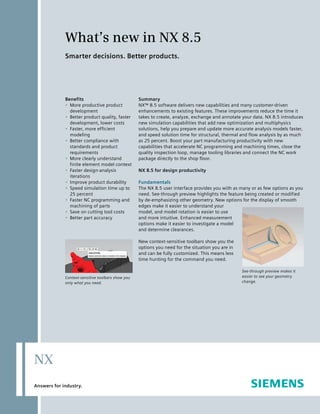
• Speed simulation time up to The NX 8.5 user interface provides you with as many or as few options as you
25 percent need. See-through preview highlights the feature being created or modified
• Faster NC programming and by de-emphasizing other geometry. New options for the display of smooth
machining of parts edges make it easier to understand your
• Save on cutting tool costs model, and model rotation is easier to use
• Better part accuracy and more intuitive. Enhanced measurement
options make it easier to investigate a model
and determine clearances.
New context-sensitive toolbars show you the
options you need for the situation you are in
and can be fully customized. This means less
time hunting for the command you need.
See-through preview makes it
Context-sensitive toolbars show you easier to see your geometry
only what you need. change.
NX
Answers for industry.
2. NX
What’s new in NX 8.5
Sketching Creating helical shapes such as springs or synchronous technology makes it easier to
Sketching in NX 8.5 has been streamlined. threads has been streamlined with new do “what if” design studies so you can
The coordinate system display in sketches commands which give you full control over explore all options and optimize your
has been simplified to make it clearer, and the properties of the helix. The resulting design.
sketch coordinate systems now have shapes are fully parametric and easier to
unique names to make them easier to modify than in previous versions.
select. You also have increased flexibility
when placing constraints, streamlining the
sketching process and reducing
development time.
Feature-based modeling
NX 8.5 delivers many usability
enhancements and new capabilities in
feature-based modeling. You can use open
profiles to create features, which auto
matically extend to the surrounding The face on the right has been labeled as a blend,
Helix creation is easier and more powerful. the one on the left has not.
geometry to create a closed feature. You
can now emboss a body with another
body, which is useful for creating dies or You can now add draft to a model using an
ensuring sufficient clearance between intersecting surface as the parting line. Freeform modeling
two parts. While this has been possible in the past, Freeform modeling in NX 8.5 has improved
the new functionality makes this action geometry creation, analysis and
There is a new way to create unions significantly faster and more efficient, with visualization features. Some commands
between two solid or sheet bodies. You 40 percent fewer features and only a third have been enhanced with new law types,
can select which regions you want to keep as many commands as the old method. giving you more tools to create the
or remove, allowing you to create your complex geometry you need. You can
desired geometry with about 30 percent Synchronous modeling enhance the visual display of your curve
fewer commands and 25 percent fewer NX 8.5 is the fifth release of NX with geometry by highlighting end points in
features. synchronous technology, and it continues several different ways. New surface and
to be enhanced and refined with new radius analysis tools help you ensure that
functionality. The existing commands are your geometry meets all necessary
now more capable and more intuitive to requirements. You can now fit a curve or a
use. You can now label faces as blends, surface to existing geometry such as facet
adding intelligence to history-free data bodies or points, which is useful for
and making it easier to get the results you reverse engineering.
want when you use synchronous modeling
to modify the geometry. New options give Data exchange
you greater control of your geometry as NX 8.5 builds on the open philosophy that
you modify it, meaning you are more likely guides Siemens PLM Software with tools to
to get the result you want the first time. work seamlessly with other systems,
Synchronous technology can now alert you protecting your design investment. With
when the changes you are attempting will the improved JT™ Export interface, it’s
You can select which part of a body you want
cause potential errors so that you can easier to control how your information is
to keep.
adapt accordingly and spend less time exported. You can save your configuration
repairing your data. The flexibility of to a file, saving time on future jobs. NX
3. NX
now reads more data from JT files, making solid model into a sheet metal part. With Visualization
the resulting NX file easier to understand this and other tools you can quickly NX 8.5 delivers improved visualization
and diagnose, which means you spend generate a robust, re-usable sheet metal tools that make it easier to understand
more time using your data and less time part from a standard solid model, reducing your models and generate aesthetically
trying to decipher it. A new wizard makes design time. correct renderings of them. A new
it easier to export data to the DXF or DWG background environment maps a
formats by streamlining the process and panoramic image onto a hemispherical
improving control over export options with dome, so as you pan around your model, it
an improved user interface. appears to be in realistic environment from
any angle, making visualization more
Routed systems design realistic and useful.
Routing in NX 8.5 makes it faster and
easier to create the geometry you need.
New capabilities allow you to mirror
routing objects to create symmetric
routing networks, saving time and
ensuring consistency. There are new Beads and dimples can now be added after bends.
options for creating and navigating runs
which make it easier and faster to ensure
compliance. It’s easer to find and replace Re-use
components with the same specifications, The NX Reuse Library, a common Visualization tools enable you to make attractive,
saving time and ensuring that require repository for all of your re-usable realistic images.
ments are met. geometry, has been enhanced for NX 8.5.
You now have the option of changing
Sheet metal design deformable parameters on a part when NX 8.5 for tooling design productivity
Sheet metal design has been throroghly you drag it from the Reuse Library, giving
enhanced in NX 8.5. You can now create you more control. When you add a Tooling design in NX 8.5 has been
dimple features before or after bends, or component to an assembly, you now have enhanced to optimize the overall mold and
put bends across existing features, and the option of viewing the component in a die design process and to improve
everything adapts correctly. NX pattern preview window to verify that it meets productivity by eliminating many manual
feature functionality has been extended to your needs before you place it. You also modeling steps.
sheet metal in 8.5, saving time when have the option to add multiple
creating multiple features. You now have occurrences of a component at the same Mold design
more options to help you create bend time. This is especially efficient for Parting surface design methodologies have
regions, making it easier to create standard parts that are used in many been improved to make the design process
compliant geometry in fewer steps. There places at once, like fasteners. more efficient. Creating and modifying
is now a wizard with cleanup and cooling channels is easier and more
conversion options to help you convert a Validation intuitive. Injection flow analysis functions
Check-Mate has been enhanced with new are now integrated into NX, permitting the
checkers that make it easier to investigate
your data and find issues before they cause
problems down the road. This makes you
more productive and ensures quality
models.
4. NX
user to perform more flow analysis inside Drafting weld symbols, including the ability to
NX . The standard parts management tool Drafting in NX 8.5 has been comprehen change the weld standard without having
has been improved to provide consistent sively enhanced in response to customer to reset the whole drafting standard in
user interaction by using the NX Reuse input. You can now create lightweight your NX session. The new function lets you
Library framework. Many new capabilities drawing views which improve performance control the size of your weld symbols more
in the electrode design process have been and reduce system resource usage. The easily. All of these changes are designed to
introduced to improve user productivity. drafting user interface has also been make you work faster and smarter when
simplified to clean up the interface and creating standards-compliant drawings.
Progressive die design make it easier to find the commands
A variety of improvements have been you need. Product and manufacturing information
made to support the more complex un- Product and manufacturing information
forming design workflows. Process support The view creation wizard has been (PMI), which embeds critical manufac
for parts with zero bend radius, bends with enhanced with new commands and turing and other information directly in
complex features such as Gusset, ribs, etc. options designed to optimize performance your 3D geometry, has been enhanced for
are now possible. Improved engineering with large assembly drawings. A new NX 8.5. The PMI user interface has been
die design (transfer and compound dies) option gives you the ability to permanently simplified and some commands have been
process supports many aspects of die align a view with other views, giving you renamed and moved to make them more
design more efficiently. greater control. intuitive to use. You now have greater
control over which PMI is displayed in
Stamping die design which places, helping to clean up and
NX 8.5 delivers new capabilities to perform manage your PMI. When trying to find the
more accurate trim angle checks for PMI associated with selected geometry,
complex parts. Support is also added for you now have the choice of viewing it in a
the complex draw die punch design permanent or temporary view. When
process that eliminates many manual extracting geometry from a body, you now
modeling processes. Plus new blank have the option of extracting PMI data
nesting capabilities perform the nesting along with it, reducing rework and helping
operations in an integrated environment. create smarter models.
Lightweight views save system resources.
You now have the option of having your
associative custom symbols update
automatically when the master you
created them from changes, helping
ensure that your symbols remain up to
date. New options give you greater control
over the linking and positioning of custom
symbols. You also have more control over
PMI is easier to understand and manage in NX 8.5.
5. NX
NX DraftingPlus NX 8.5 for simulation productivity understand where you might need to edit
NX DraftingPlus delivers enhanced 2D node locations for connections to the rest
design capability inside NX, and on its Whether developing race car components of the assembly.
third release, continues to add function for next week’s race, or the structure for
ality. You can now create Drawing the next-generation submarine that will
Booklets, which are multiple drawing files launch five years later, all development
combined into a structure that allows you teams face time constraints that are costly
to group together the drawings needed to when designs fail and schedules aren’t
define an assembly or study. Since the files met. NX for Simulation is a modern
in the booklet are managed as a single simulation environment that can help
unit, it’s easier to manage them; and the development teams engineer their
impact on system resources is reduced, products right the first time. With the 8.5
making the whole system faster. release, NX CAE introduces over 240 new
capabilities in areas such as simulation
modeling, structural, thermal, flow,
motion, multiphysics and optimization
Assembly
analyses.
An assembly FEM of a disk brake assembly. 1: The
Part A Part B Part C Part... Simulation modeling assembly FEM is both the displayed and the work
FE model in context NX CAE 8.5 expands part. 2: The disk is the work part. 3: The brake pad
Drawing is the work part. 4: The caliper is the work part.
(intro sheets)
Drawing A Drawing B Drawing C Drawing...
upon its unique distributed CAE
environment for building analysis model
Drawing booklet
assemblies by allowing you to edit a single
FE component model in the context of the The new FE model in context capability
Drawing bookets help you organize your drawings. overall assembly. In NX CAE 8.5, you can supports many new workflows, including
now set the work part independently of the following:
the displayed part, which allows you to see • With an assembly FEM displayed, make a
It is now possible to easily move drawing and reference the rest of the FE assembly component FEM the work part to create
objects from one view to another while while editing just the FE component or edit meshes, clean up or modify
maintaining their associativity and proper model. In previous releases, if you wanted polygon geometry, or modifiy physical
scale, orientation and style. You can now to generate a mesh or edit an existing and material properties.
smash a drawing view, meaning the mesh, you would first need to change the • With an assembly FEM displayed, make a
objects in that view are no longer displayed part to the FEM file containing subassembly FEM the work part to
associated with the view itself. This gives the geometry. So you would have only resolve label conflicts or edit connection
you more flexibility in placing your objects seen the FE component displayed on the meshes.
in a 2D design environment. screen, which could make it difficult to
6. NX
• With a simulation displayed, make the • Fewer mesh mating conditions and • A new ability to create face pairs based
component FEM the work part to modify stitch edge recipes are recreated and on the ratio of thickness to face size is
meshes or polygon geometry in the replayed. particularly helpful for models with
context of applied loads and boundary • Fewer meshes are deleted and recreated. highly variable thickness values.
conditions.
• With a FEM displayed, make the These changes speed the update process,
idealized part the work part to create or reduce potential manual rework and can
modify geometry in the context of the save you significant time when working
mesh. with large models.
FE model in context significantly speeds Mid-surface productivity enhancements
the modeling process because each of A number of enhancements have been Illustration of “rolling ball” algorithm where the
these workflows help engineers make the made to the mid-surfacing capabilities in software uses the diameter of a ball at a given
right modeling decisions in the right NX CAE 8.5. These changes can provide a location as the thickness of the part at that
location.
context of the problem to be solved. better result on the first pass, and
ultimately allow you to mid-surface your
Faster FE model updates NX CAE 8.5 part up to five times faster. Some of the
includes improvements that speed the new enhancements to the mid-surface Solver-specific element quality checks
overall update process for the FE model command include: The element quality command now can
when the design changes. Specifically, • The progressive pairing option uses a evaluate the quality of elements in your
these improvements are designed to new “rolling ball” thickness calculation model based upon the specific quality
minimize the amount of polygon geometry algorithm which provides more granular criteria employed by the solver you are
that is affected when there are changes to thickness information throughout a using. This means NX CAE can highlight
the underlying CAD geometry. body. This new algorithm calculates element quality issues before you export
more accurate thickness data for both your input data file and run the solver,
Now, during the polygon geometry update constant and variable thickness parts. which saves you time and eliminates the
process: This results in more accurate face pairs frustration of finding quality issues at solve
• Fewer polygon faces are deleted and and you spend less time editing the data time. Solver-specific quality checks are
recreated. after mid-surface generation. supported for the following solver
• Manual modifications that you make to • Automatic pairing now available for environments:
the polygon geometry are now tangent-continuous parts helps you • NX Nastran®
preserved. reduce manual work on surfaces that are • MSC Nastran
tangent within a specified angle. • Abaqus
7. NX
• Ansys (Note: The Ansys solver-specific design geometry and other parameters.
checks in NX are consistent with the This is useful for tradeoff studies and to
quality checks in the standard Ansys determine optimum operating conditions
solver. They are not consistent with the for a product. For instance you may need
quality checks used by the Ansys to minimize the temperature of a critical
Workbench platform.) component within an electronic device
• LS-Dyna through variation of airflow patterns. One
way to reduce the temperature may be to
Engineering optimization optimize the airflow rate into the device,
NX Shape Optimization NX Shape which you can then set as the design
Optimization is a new NX CAE product Left: Original design with high stress concentra variable. NX CAE will then automatically
introduced in this release. NX Shape tion. Right: New design after shape optimization. adjust the flowrate, update the model and
Optimization helps engineers suggest solve, and evaluate the resulting
specific detailed improvements to an temperature at the component. NX CAE
existing design when only minor changes then automatically iterates this process
and improvements are permitted due to until the desired objective is achieved –
design constraints. In these cases, leaving you with the optimal flowrate and
engineers are typically looking to minimize temperature in a fraction of time it would
stress concentrations, or to maximize take using conventional means.
selected natural frequencies, which are
factors that can extend product life and
durability. To achieve the objective, each
design node is displaced with the objective
of reducing the local stresses. In the high-
stressed area, the design nodes are
displaced outward and the structure
grows; in the low-stressed area, the design
nodes are displaced inward and the
structure shrinks. The resulting node Overlay of new design and old design to show how
dimensions have changed.
locations can be communicated to the
design team in the form of an STL file,
which allows designers to visually
understand how to update the geometry. Geometry optimization in NX Thermal
and NX Flow NX CAE 8.5 introduces Minimizing critical component temperature by
geometry optimization within the NX optimizing flowrate.
Thermal and NX Flow products. Geometry
optimization lets you drive the design
toward an optimal solution by varying
8. NX
Structural analysis edges of axisymmetric elements. Edge-to- Thermal and flow analysis
Edge-to-edge glue and contact support edge linear contact can be used in Multithreading to achieve faster
for NX Nastran NX Nastran is a leader in solutions for linear statics, normal modes, thermal computations Multithreading
structural analysis solutions and is at the buckling and modal frequency and takes advantage of multicore and multi-
forefront of developing new connection transient response. processor hardware to speed up the
types that allow engineers to build their thermal computations. The new
models faster. NX Nastran 8.5 introduces Bolt preloads on solid elements for NX multithreading option in NX Thermal is
new glue and contact connections which Nastran NX Nastran 8.5 adds a new most useful for radiation-dominated
are also supported within the NX CAE 8.5 capability supported by NX CAE 8.5 to models. For transient runs, depending on
release. allow more detailed representation of output intervals, run time can be reduced
bolts, including contact between hole and by up to about 25 percent (using 4 cores).
New edge-to-edge gluing is a simple and bolt, which gives you more accurate
effective method to join dissimilar shell results. New fully coupled scheme for parallel
meshes. Glue connections, between the flow solver NX CAE 8.5 introduces a fully
edges of shell elements in the same plane, coupled scheme for the parallel flow solver
simplify the modeling process for the in NX Flow, which helps to solve large
engineer without compromising accuracy models faster. This fully coupled pressure-
of the structural analysis. velocity scheme is now used by default
and is better suited for solving steady-state
models or transient models using larger
timesteps. In the previous release, the
fractional step scheme was the only
Model bolt preloading on solid elements such as
scheme used by the parallel flow solver,
for the bolts mounting this manifold assembly. but is more suitable for transient models
with small timesteps.
Import Fibersim HDF5 files in NX
Laminate Composites Fibersim™ software Multiphysics
is now a member of the Siemens PLM Durability analysis based on flexible
product family, and so NX CAE is able to body motion simulation results You can
strengthen its integration with Fibersim. In now easily perform a durability analysis on
Edge-to-edge glue allows easy connection between
two dissimilar shell meshes along an edge.
NX CAE 8.5, you can directly import a component that was simulated as a
Fibersim ply-based layups from a Fibersim flexible body in a motion analysis. In NX,
HDF5 (*.h5) file into NX Laminate you can seamlessly move from CAD
Composites. In previous releases, you assembly to a motion study using a flexible
Similarly, NX CAE 8.5 supports the new could only import layups from a Fibersim body, and then use the results of the
edge-to-edge contact capabilities in NX XML file. Importing the HDF5 file gives you
Nastran 8.5 to define contact conditions more information for each ply than is
between selected polygon or element available in the XML file, such as:
• The starting point of the draping
• The direction of the draping
• The orientation angle
9. NX
motion study to kick off a durability Motion analysis NX 8.5 for manufacturing productivity
process on the component in question. Suppress/unsuppress motion objects
Based on the durability results, you could A new feature in NX Motion Simulation NX 8.5 boosts part manufacturing
even use the new NX Shape Optimization allows you to suppress individual motion productivity in the machinery,
module introduced in this release to objects and their dependent objects from turbomachinery, aerospace, medical, and
smooth out areas of concern in the being included in the active solution. For mold and die industries. Save time
geometry that would help extend example, you can suppress a link to programming and machining parts with
product life. remove it from the solution. That link’s new machining operations, more tool path
dependent joints and any other dependent control and easier ways to automate
objects – such as springs, markers, programming. Close the quality loop by
bushings, etc. – will also be suppressed. creating CMM inspection programs and
This saves time so that you can quickly analyzing results all directly within NX.
simulate design alternatives without Save on tooling costs and use the right
having to physically delete or recreate data from NC programming through to
objects in your motion simulation. If you machining with new tool library and CAM
then unsuppress one of the dependent data management capabilities.
objects, that object’s parent object will
also be unsuppressed. Machining productivity
NX CAM delivers the next level of NC
programming productivity with specialized
industry-specific capabilities.
NX CAM for machinery Volume-based
2.5D milling provides a very fast and
intuitive method of programming
prismatic parts. Simply select faces such as
walls and floors within on the 3D part
model to define the machined volumes. An
instant visual preview provides fast and
easy validation of the planned machining
operation. Programming can be 5 to 10
times faster. The system continuously
keeps track of uncut material and
minimizes air-cutting, reducing machining
time up to 10 percent.
Durability results based on a flexible body motion Suppress motion objects from motion simulation
simulation of motorcycle suspension bracket. model for quick debugging or evaluation of
alternative ideas.
10. NX
Multi-stage machining processes also track incremental rough/finish operations Mold and die Valley restmilling is
the in-process workpiece for greater between thin blades to maintain rigidity enhanced with new hybrid Z-level and
efficiency. Updated blank models are and improve finish quality. projected patterns that identify, sort and
automatically maintained for each station. prioritize the valleys to find the best
cutting motions. By combining steep and
Advances in feature-based machining nonsteep cutting approaches into a single
automate the sorting of machining pattern, you can easily clean out valleys
operations across multiple setups for with various orientations and achieve a
faster, easier programming. smooth finish.
New finish patterns allow incremental finishing
for thin blades.
Aerospace and medical Swarf or flank
milling with the new contact point control
reduces passes and produces a better
surface finish on complex parts that
require 5-axis strategies that cut with the Cutting directions are optimized for the best finish.
side of the endmill. By positioning the tool
Volume-based 2.5D milling speeds programming tip past the contact point, more material
for machinery. can be removed per pass leaving smaller Tool library The enhanced NX CAM
cusps and extending tool life. tooling library supports a broader
definition of tools that includes tooling
Turbomachinery milling New roughing devices and holders. It also includes
operation options improve machining context information for faster machine
efficiency for turbines and multibladed simulation setups such as pocket
parts. By adding depths to slotting assignments, mounting points and visual
motions, roughing operations can be previews.
assigned higher feed rates or deeper
depths. Additional finishing options The new Manufacturing Resource Library
provide swarf (flank) milling and also allow (MRL) is used to manage tooling vendor
catalogs and preferred tool assemblies, as
well as your custom resources. The MRL
stores and classifies its content in
5-axis flank milling options make smaller cusps.
11. NX
Teamcenter, with a full range of search CMM measurements are read back into NX Data management
functions and graphical displays so you as .mea or .dml files. They are compared to CAM Data Management helps to eliminate
can easily find and access your tools. From the measured datums, including the the delays and costs that come with bad
NX CAM, you can search the library, find associated tolerances according to ANSI data. The introduction of the
the tools you need, and pull in accurate 3D Y14.5, ASME Y14.5 or ISO 1011 standards. Manufacturing Resource Library (MRL) and
models of the selected cutting tools right Measurements are displayed in the the Manufacturing Resource Library
into your CAM programming session. operation navigator as a list and linked to Connect for NX products make big
the graphical display for each measure advances in building and making available
ment. Best-fit analysis and verification help complete and accurate tool data.
illuminate the possible causes of tolerance
failure and assist in decision making that Manufacturing Resource Library The
will improve component quality. new Manufacturing Resource Library (MRL)
is used to manage tooling vendor catalogs
NX CMM inspection programming CMM and preferred tool assemblies, as well as
inspection programmers work directly in your custom resources. The MRL stores and
the NX 3D environment and use the PMI classifies its content in Teamcenter,
information, GD&T applied right to the Siemens PLM Software’s comprehensive
solid, to generate programs quickly. NX 8.5 system for managing product lifecycle
Powerful new tool library capabilities available for delivers time saving updates, such as new management (PLM) data and processes,
NX 8.5. transitions methods that find key with a full range of search functions and
interferences and automatically resolve graphical displays so you can easily find
them. Scans are previewed with probe and access your tools. From NX CAM, you
CMM inspection programming and orientations to make sure the desired can search the library, find the tools you
results analysis results are achieved. More complex scans need, and pull accurate 3D models of the
Maximize the efficiency of your complete can span multiple features. selected cutting tools right into your CAM
quality inspection process with the programming session.
enhanced offline programming and new
inspection results analysis capabilities
in NX.
NX CMM data analysis Users can quickly
see and evaluate their “as-built” measure
ments in the graphical NX environment,
right next to the “as designed” models that
drive the CMM inspection programs.
Putting the measurement results into
context helps manufacturers find the most Tool definitions include solid models ready for NC
simulation.
effective approaches to achieve quality 5 axis scanning with NX 8.5 CMM Inspection
improvements. Programming.