
Recommended
More Related Content
Similar to Project_1
Similar to Project_1 (20)
Recently uploaded
Recently uploaded (20)
Project_1
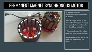
- 1. PERMANENT MAGNET SYNCHRONOUS MOTOR -It is an electronically commutated motor powered by DC Supply -This DC supply is used by the means of switching power supply to drive each phase of the motor by a closed loop controller. - The controller provides pulses of current to the motor winding . -These pulses further control the speed and the torque of the motor.
- 2. PARAMETER MECHANICAL COMMUTATOR ELECTRONIC COMMUTATOR Type of Commutation Brushed commutation because of the mechanical contact between the brush and the commutator Electronic Commutation using the power semiconductor devices like the MOSFET,transistor etc Position of Commutator Commutator are arranged on the rotor Commutator are arranged on the stator Speed Range Low High Maintenance High Low Control Difficult to control Easy to control Life Shorter Life Longer Life
- 3. Construction of a PMBLDC Motor:
- 4. Operating Principle/Operation: ● Self-start motors don’t require any external force for starting. ● As power is supplied the armature winding draws current and flux is produced by the permanent magnets. ● The armature conductors experience a force by the Fleming’s left hand rule. ● This force being reactive in nature develops a torque for rotor rotation. ● If the produced torque is greater than the opposing frictional and load-torque,then the motor starts to rotate.
- 5. ● As the speed increases there exists a relative angular velocity between the permanent field and the armature conductors. ● This relative speed produces as emf in the armature conductors. ● Due to the lenz's law this back emf opposes its cause,that leads to the reduction in the armature current and the developed torque. ● The rotator attains the steady state speed when the developed torque gets exactly equal to the opposing frictional and load torque. ● On increase in the load torque, the rotor speed starts decreasing and back emf generated in the armature winding also starts decreasing. ● And since,the supply voltage remains constant the supply is increased ● The increase in the armature current increase the torque in the motor ● Motor attains a new equilibrium position when the motor torque is equal to the new load torque.
- 6. Classification of PMBLDC Motors: One-phase One-Pulse One-Phase two-pulse Two-phase two-pulse Three-phase three-pulse Three-phase six-pulse 1)This uses only one semiconductor switch 2)Has only one armature winding 3)Rotor position sensor gets turned on and off on being influenced by the N and S pole respectively 4)Torque is only developed for half cycle 1)Has one armature winding 2)Two-static switches used 3)It requires a 3-phase DC supply 4)Requires a position sensor, two switching position sensor and 2 switching devices S1 and S2. 5)S1 is tuned on and off on the influence of the N and S pole and the reverse happens in the case of S2 1)It has 2 armature windings each displaced by 180. 2)Two semiconductor switches are used. 3)It requires 2 independent Phase windings 1)It has 3-phase windings displaced by an angle of 120 electrical apart. 2)It has 3 switching devices. 3)3 position sensors are required. 1)It has three-phase windings. 2)It requires 6 semiconductor switches. ADVANATGES: 1)The utilization of switch and winding is 50% 2)Inertia is such that the rotor rotates contionously ADVANTAGES 1)Winding Utilization is better 2)A more uniform torque is devloped ADVANTAGE: It produces a better torque waveform Multi-phase Multipuse 1)It has embedded permanent magnet rotor 2)The stationary armature has parallel and independent phase windindgs
- 7. Control of PMBLDC Motors:
- 8. PMBL 120 Degrees Square-wave commutated DC-Motor: ● Three-phase bridge inverter composed of six-switching devices is used. ● High-side device turned on in one phase and low-side device is in another phase. ● Both high & Low side devices are turned off in the remaining phase. ● This commutation technique always conducts electric current through 2 windings at any one-time ● The phase voltage remaining to a motor’s neutral point always becomes Vdc/2.
- 9. PMBL 180 degrees Square-Wave Commutated DC-Motor: ● 3-phase bridge inverters composed of six-switching devices is used. ● At once, only either the upper side or the lower side of the same arm are turned on. ● Value of the phase voltage here is Vdc/3 or 2Vdc/3. ● Current here flows from the positive to the negative end of the DC bus. ● It produces a current ,4/3 times and torque 35% greater than commutation in 120 degrees ,if operated on the same voltage.
- 10. MICROCONTROLLER BASED PMBLDC MOTOR: ● BLDC motor supplied with a power converter having 6 static devices ● Tachometer mounted on shaft to obtain the speed feedback signal ● Hall-sensors used to provide position signal ● Stator current identified by Current sensor ● Amplitude identified by Optically Isolated Amplifier ● Output signals are multiplexed and converted into digital form by ADC. ● During normal operation,Input-output terminals sent to command and the line current,rotor position and speed are sensed and fed to the CPU. FUNCTIONS OF A MICROPROCESSOR: ● Receives current signal,position signal,speed signal and current references ● Processes the input signals and gives the appropriate triggering signals to the switches. ● After the Process, Issues control to base/gate drive circuit where the signals are amplified.
- 11. TORQUE EQUATION OF A PMBLDC MOTOR:
- 12. EMF EQUATION OF A PMBLDC MOTOR:
- 13. APPLICATIONS OF PMBLDC MOTORS Computer Hard Drive, DVD/CD Player ELECTRIC VEHICLES INDUSTRIAL ROBOTS WASHING MACHINE COMPRESSORS/DRYERS FANS/PUMPS/BLOWERS
- 14. THANK YOU