
Recommended
More Related Content
What's hot
What's hot (20)
Similar to Part technical cleanliness/Millipore
Similar to Part technical cleanliness/Millipore (20)
Recently uploaded
Recently uploaded (20)
Part technical cleanliness/Millipore
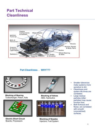
- 1. 1 Part Technical Cleanliness XX.XXXX Blocking of Bearing Turbocharger, Piston, Axle Blocking of Valves ABS, Hydraulics Part Cleanliness… WHY??? Blocking of Nozzles Injectors, Fuel System Electric Short Circuit Boards, Processors • Smaller tolerances make systems more sensitive to dirt. • Cleanliness and system life times are correlated. • Large residue particles (killer particles) may cause function loss. • Both Exhaust and Noise, are correlated with smooth (unscratched) surfaces.
- 2. 2 Component Cleanliness of Fluid Systems in Automotive Complying with ISO Standards Abstract: As the presence of particulate contamination in the lubricant is the major cause of failures and short component life of fluid systems, companies in a variety of industries are focusing attention in achieving and maintaining system cleanliness. The presence of machining and assembly debris in the fluid system at start-up and during the initial running phase will cause a substantial increase in the wear rates of the system, further generating large particles, with the consequential loss in performance and component life. It will also increase the probability of sudden and catastrophic failure of the system. To achieve clean components requires appropriate manufacturing, cleaning and measurement processes. Accurate assessment of the effectiveness of components and parts cleanliness is related to given contaminant extraction methods, analysis and data reporting. ISO standards are continually being developed to control procedures and implement a consistent cleanliness evaluation process. This article explains the processes in these standards and how similar procedures have been adapted to suit the requirements of the above industries. It also gives guidance and recommendations on the implementation of these standards so that the best use can be made of them. 1. Introduction The need for component cleanliness was first identified in the 1960s when the aircraft industry started using hydraulic flight systems. The last 10 years has seen more and more industrial sectors implement component cleanliness programs as they realize the technical and commercial benefits. Foreword: The fluid power industry was the major developer of ISO standards through ISOTC131/SC6 until 2002 when the automotive industry embarked on a project to develop their own standards through ISOTC22/SC5. Although the processes used would be very similar to those developed by TC131/SC6, the automotive industry considered that their requirements were sufficiently different to warrant new standards. For example, the automotive industry focus is on the incidence of small numbers of large particles (>1000 μm - so called ‘killer particles’) residual after production as they could have serious safety consequences, whereas these particles should be filtered out of fluid power systems during production. This split development has led to small differences in both terminology and procedures. For instance, the process of removing particles from components is called ‘extraction’ in ISO16232. This document summarizes the standard practices related to contaminant extraction, collection, analysis and data reporting for cleanliness evaluation of manufactured parts and components, specifically being applied to the fluid systems (lube, fuel and hydraulics) in automotive and fluid power markets. 2. Contaminant Extraction Methods 2.1 Extraction selection with geometry The selection of the most suitable extraction method(s) is guided by the followed principles: • Extraction method must be selected for the geometry of the component so that the extraction liquid can reach the controlled surfaces.
- 3. 3 • Extraction method must be directed to only remove particles from the controlled surfaces. • Component geometry must allow the particle to be transported away by the extraction method. • Extraction method must be validated. ISO18413 provides recommendations for selection of contaminant extraction methods: - Pump/Motor - End-use simulation method. - Valve Cylinder - End-use simulation method. - Manifolds/System - End-use simulation method. - Gear/Shaft/Plates - Pressure rinse or ultrasonic. - Spool/Pistons - Pressure rinse or ultrasonic. - Reservoir - Pressure rinse or agitation. - Hose/Pipe - Agitation or ultrasonic. To obtain repeatable results, the process attributes must be consistent. 2.2 Agitation extraction method (Slosh test) The contaminants are extracted by partially filling the component with a known volume of test liquid (between 30 to 50% of the component volume), sealing its openings, and agitating or ‘sloshing’ it in order to detach the particles from the controlled surfaces and suspend them in the test liquid for subsequent analysis. The efficacy of the agitation method depends on type of agitation, duration of agitation and choice of test liquid. This method is only suitable for hollow components like hoses or pipes whose size is such that they can be readily and consistently agitated. Applicable standards: ISO16232 Part 2; ISO18413 Clause 5.3 2.3 Pressure rinse extraction method The contaminants are extracted from the controlled surfaces of the component by pressure rinsing with a jet of filtered test liquid which removes the particles from the surfaces and carries them away for subsequent analysis. The pressure rinse liquid dispenser is a device for providing clean test liquid at a suitable pressure and a flow rate capable of extracting the particles in an effective manner. The efficacy of pressure rinsing depends on pressure, flow rate, distance, angle, shape and size of the nozzle, rinsing time and liquid volume per unit area. Applicable standards: ISO16232 Part 3; ISO18413 Clause 5.4 2.4 Ultrasonic vibration extraction method The contaminant is removed by subjecting the item to ultrasonic vibration. The principal characteristics of the ultrasonic equipment are power, frequency and bath size. In general, by applying transducers to the floor or wall surfaces 3. Extractions for cylindrical pipe of hydraulic, lube and fuel components This section outlines the extraction methods to assess the cleanliness of the wetted inner side of cylindrical or pipe type of hydraulic, lube, fuel components and subassemblies. 3.1 Extractions of the contaminant from passages or holes of component The functional test method, according to ISO16232 and ISO18413, is able to properly and effectively detach the particles that are residual in narrow flush passages like drain or return lines in a manifold block or casings. 3.2 Extractions of the contaminant from inside of hydraulic tube and hose Flushing rig complying with ISO16232 Part 5 is best to validate cleanliness of hoses and pipes and this needs a flow rate to give turbulence in the pipe with a Reynolds Number (Re) of >4000 i.e. well into the turbulent regime. And a variable delivery pump is desirable to suit component size. The viscosity used in these test rigs is usually higher than usual extraction liquids because of the minimum viscosity required by the circulating pump. The rig should also include on-line particle counting so that the progress of flushing can be continuously monitored and terminated when a RCL is achieved. This approach can achieve considerable savings in costs over more ‘conventional’ methods of collection. It is recommended that at least 10 mL extraction liquid/cm2 of wetted surface area is used for pressure rinsing hoses and pipes. If the calculated amount of extraction fluid is less than 2 litres, then 2 litre shall be used or if it exceeds 20 litre, 20 litre shall be used, unless otherwise specified. 4. Protocol and Validation for Contaminant Extraction 4.1 Package during transportation If particles are detached during transportation of the test components and/or from packaging, these have to be included in the cleanliness test. They are collected using appropriate extraction method(s). During handling and storage of test components, it shall be safeguarded that no contaminants are deposited on or removed from controlled surfaces. To prevent loss of particles during transport it may be necessary to seal openings in the test components with either tape or a suitable plug. Applicable standards: ISO16232 Part 2, 3, 4 & 5 4.2 Blank test • A blank test is performed to verify that the environment, operating conditions, and equipment used in the extraction procedure do not contribute a
- 4. 4 significant amount of contamination to the component being analysed. To ensure process consistency, a blank test should be performed at regular intervals using identical test parameters. • For the determination of system blank values, identical conditions as experienced during testing of the component are applied but with the component omitted (see 3.3). • If the blank level exceeds 10% of the cleanliness of the component (presumed or measured), then either the process or environment is too dirty and re-cleaning is necessary, or the contamination level of the component is to low and it is necessary to increase the number of test components analysed in order to collect more contaminants and thus fulfil the 10% limit. 4.3 Validation of contamination extraction process It is essential that the contamination extraction procedure is validated, so that its effectiveness is confirmed. Extraction Step Figure 1. Validating the extraction process. The process is: •Determine the most suitable extraction method and the operating parameters. •Perform two extractions and for each of two samples to establish either the total mass of contaminants or total number of particles. Note that ISO16232 requires the extraction of three samples. For particle numbers, this should include the total numbers of particles larger than •the smallest particle sizes specified in the inspection document. •Divide the result of last sample by the sum of all the results obtained. •If the value obtained is less than 10% of this sum, the end point is reached, and the extraction is complete. The cleanliness level of the component is the sum of the extractions. •If the value obtained is >10%, further extraction is necessary. If six extractions have been performed without reaching the 10% value, then the extraction parameters are not suitable and will have to be modified. ➢ The component is made cleaner. 5. Analysis Methods 5.1 General A variety of standard, contaminant analysis methods and data reporting formats are available to produce the required part or component cleanliness data. Both ISO16232 and ISO18413 describe three basic contaminant analysis methods: gravimetric particle size, distribution and chemical composition. Largest particle size is included in particle size evaluation. The major difference separating ISO16232 and other standards is the requirement to analyze all of the extraction liquid so that all particles in the extraction are analyzed and the larger (‘killer’) particles, typically at much lower concentrations, are not missed. Because of this need, the microscopic procedures of ISO16232 are completely automated using image analysis. 5.2 Gravimetric analysis method Extraction, filtration, drying, and weighing Precision components must be free of contaminants to work properly. Parts that are made with unclean components can fail prematurely. Technical cleanliness is the process of measuring the level of contamination from these particles to help ensure high-quality finished products. In the first of this six-part blog series, we will take a close look at the first step of the technical cleanliness workflow—preparation (extraction, filtration, drying, and weighing). First, let’s look at where preparation fits into the overall technical cleanliness inspection process: • Preparation o Extraction o Filtration o Drying and weighing • Inspection o Image acquisition o Particle detection o Particle size measurement and classification o Particle count extrapolation and normalization o Contamination level calculation o Cleanliness code definition o Maximum approval check o Separation of reflective and nonreflective particles o Fibre identification o Results review o Reporting ➢ Extraction The components to be tested are placed in an extraction cabinet in a clean room, and any contaminant particles or 0 10 20 30 40 50 60 70 80 90 100 110 1 2 3 4 5 6 CleaninessValues(Ci) Number of Samples DECLINING CURVE Decay CriterionBlank Level
- 5. 5 residues are removed via flood, squirt, rinse, or ultrasonic bath. For the vast number of functionally relevant components in automobiles, extraction with a liquid is suitable. The rinsing liquid must be compatible with the component as well as the filtration device. Note that the extraction cabinet must be cleaned regularly to avoid becoming a source of contamination. For this reason, the empty cabinet is flushed several times. The washing rinse is then filtered and examined for particles. The amount of residue becomes constant after 3 to 4 washing cycles, which results in a background value for the given configuration (rinse, cabinet, and filter). It is sufficient to weigh the filter membranes to obtain this blank value. ➢ Filtration The washing rinse is filtered through a membrane, and the extracted particles are collected on the filter. This filter is clamped in a holder that is part of the extraction cabinet. If the washing rinse is an oil, it’s filtered directly. A defined quantity (about 50 ml) of oil is drawn through a vacuum filter holder. The particles remain behind on the filter. It’s important to note that a filter will not usually be covered completely with residue particles (the border of the filter is covered by a seal that results in a reduced flow-through area). A filter membrane clamped and in use with an extraction cabinet Filter sizes vary from 25 mm to 90 mm in diameter. The typical filter size and quasi-standard for technical cleanliness is 47 mm. Filter membrane materials include: • Cellulose: Excellent compatibility with aqueous solutions • Polyester: Uniform image background; easy to set threshold for particle detection • Glass fiber: Ideal for solutions with high levels of suspended solids or high viscosity • Nylon mesh: Very good resistance to almost all solvents; needs a white support layer as it is transparent ➢ Drying and Weighing: The filter membrane is dried in preparation for further analysis. The rinse fluid or oil can be removed using an exicator (a desiccator), a drying oven, or dedicated equipment. The dried filter membrane (with all impurities on it) is then weighed using an analytical balance with an integrated windshield. The gravimetric result gives the first value for the residue particles, but the size, shape, and other particle parameters are still unknown. The weighted filter membrane is next mounted on a filter holder, ready for the next phase of the technical cleanliness inspection process—image acquisition. 5.3 Particle counting by microscope The inspection process includes the following steps: • Image Acquisition and Stage Movement: The dried membrane filter is mounted on a motorized microscope stage so that the images needed for inspection can be acquired. • Particle Detection: Membrane filter images are examined for particles, which appear as dark areas against a bright background. • Particle Size Measurement: Detected particles are measured according to different parameters, including Maximum Ferret and Equivalent Circle diameter. • Particle Size Classification: Once particles have been measured, they are grouped into different size classes. The two major size classes are differential (defined by a minimum and maximum size) and cumulative (defined only by a minimum particle size). • Particle Count Extrapolation: A defined area on the membrane filter is scanned and checked for particles. These areas may include filter size (the total area of the filter), flow-through area (the filter area covered with particles), maximum scan area (the maximum possible area to be scanned for inspection), and inspection area (the actual scan area defined by the user). • Particle Count Normalization: The extrapolated particle count is normalized to the comparison value, enabling the comparison of multiple measurements. Normalization methods include washed area (particle count is normalized on a 1000 cm2 area), washed volume (particle count is normalized on a 100 cm3 area), washed parts (particle count is normalized on a single sample
- 6. 6 part), and filtered fluid (particle count is normalized on a filtered fluid of 1 ml or 100 ml). • Contamination Level Calculation: This level of classification is determined not by particle size but by the total number of particles in a defined contamination class (classes are defined for most international standards). • Cleanliness Code Definition: Some standards reduce the representation of measured data to a brief description. This Cleanliness Code is defined by the standard and is composed of particle size classes and contamination levels. • Maximum Approval Check: Checking for a maximum approval value is an optional step. If a maximum value is required, it is specified in the inspection configuration and may be an absolute number of particles or a maximum Cleanliness Code. • Separation of Reflective and Non-Reflective Particles: The distinction between metallic and non-metallic particles is made by determining whether particles reflect light or not (extremely important as metallic particles stand to cause much greater harm than non-metallic particles). • Fiber Identification: Fibbers detected on the membrane filter often have a different origin (i.e., work clothes or rags) than the other particles found on the filter. Fibers thus need to be recognized and analysed or disregarded depending on the standard being used for assessing the cleanliness examination. • Results Review: The following operations are possible as part of this review: the deletion of items incorrectly identified as particles; the splitting of particles located close together and incorrectly identified as a single large particle; the merging of particle segments located close together and incorrectly identified as separate particles; the correction of incorrect particle labels (i.e., metallic vs. non-metallic). • Report Creation: A technical cleanliness inspection report may include the description of certain particle acquisition parameters, particle classification tables, particle area coverage details, and images of the largest particles. 6. Data Presentation and Reporting There are major differences in the way that data is reported in the various standards, thus: • ISO16232 reports interval counts (differential counts). • ISO18413 reports cumulative counts. All three ISO standards abbreviate the particle count data into component cleanliness coding systems as described below. These systems are based on a geometric power series with a constant to describe the range in number from very clean to very dirty in a convenient way. Note that the numbers of particles quoted are rounded up or down to two significant figures. Also, the codes can only be compared if the particle count data is presented in exactly the same way. 7. Conclusions and Recommendations These standards are used for auditing the cleanliness of components before their assembly into a system. The cleanliness level of components shall be managed by the specification established by two parties who are the supplier and end-user. • The following are recommended to ensure efficacy of the cleanliness evaluation process: • When implementing a cleanliness audit of components, the contaminant extraction method should be reviewed to ensure their efficacy and compliance to ISO16232. • Blank tests should be performed on all equipment used for extracting and analysing particles from components to verify or to validate the cleanliness of the equipment and environment. • If the blank level exceeds 10% of the measured or presumed component value, it is necessary to either investigate the cleanliness of the various procedures or if it is acceptable, to increase the number of test components analysed in order to collect more particles and thus fulfil the 10% limit • The extraction method should be selected for the geometry component and be validated. The pressure of test liquid should be adjusted to obtain a jet of sufficient power to remove and transport the particles from the controlled surface without degrading or dissolving the surface material of the component. The selection of the nozzle is equally important and may have to be changed to suit the location e.g. a needle- shaped jet is used for drillings and narrow passages and a fan-shaped nozzle is used for flat surfaces. 8. Reference [1] ISO16232, Road Vehicles - Cleanliness of components of fluid circuits. [2] ISO18413, Hydraulic Fluid Power - Cleanliness of parts and components - Inspection document and principles related to contaminant collection analysis [3] ISO4405, Hydraulic Fluid Power - Fluid Contamination - Determination of particulate contamination by the counting method using an optical microscope. [4] ISO11500: 2008, Hydraulic Fluid Power - Determination of the particulate contamination level of a liquid sample by automatic particle counting using the light- extinction principle. 9.Contact For more information Please contact-Suraj Jathar. Phone Number :9595205868.