
Recommended
More Related Content
More from Ryan Kerry Jy
More from Ryan Kerry Jy (20)
Recently uploaded
Recently uploaded (20)
Building Structures Project 1
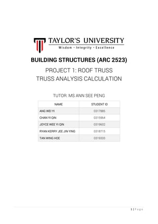
- 1. 1 | P a g e BUILDING STRUCTURES (ARC 2523) PROJECT 1: ROOF TRUSS TRUSS ANALYSIS CALCULATION TUTOR: MS ANN SEE PENG NAME STUDENT ID ANG WEI YI 0317885 CHAN YI QIN 0315964 JOYCE WEE YI QIN 0319602 RYAN KERRY JEE JIN YING 0318715 TAN WING HOE 0319333
- 2. 2 | P a g e STEP 1: Analyse the Reaction Force Roller Joint has one force acting on Y-axis; Pin Joint has two forces acting on both Y-axis and X-axis. Diagram above assumes the direction of the force for calculation. Force Equilibrium: Total Moment = 0 150(1) - 50(3) + 100(1.25) - REy(4) = 0 REy = 31.25kN Total Fx = 0 100 + 100 - REx = 0 REx = 200kN Total Fy = 0 -150 - 150 + 50 + REy + RAy = 0 RAy = 218.75kN Therefore, forces of each joint: 218.75kN 31.25kN 200kN CASE STUDY 1 | RYAN KERRY JEE JIN YING 0318715
- 3. 3 | P a g e STEP 2: Analyse the Internal Forces (i) Analyse all the joints (ii) Assume all the internal forces are tension JOINT K: JOINT A: JOINT J: JOINT B: tan 𝜃 = 1.25 1 𝜃 = 51.34° FAJx = FAJcos 𝜃 FAJy = FAJsin 𝜃 Total Fx = 0 FAB + FAJx = 0 FAB - 88.04 (cos51.34°) = 0 FAB = 55kN (Tension) Total Fy = 0 FKA + Ray + FAJy = 0 -150 + 218.75 + FAJy = 0 FAJsin 𝜃 = -68.75Kn FAJ = -88.04kN = 88.04kN (Compression) Total Fy = 0 -150 - FKA = 0 FKA = -150kN = 150kN (Compression) Total Fx = 0 FKJ =0 𝜃 = 51.34° FAJx = FAJcos 𝜃 FAJy = FAJsin 𝜃 Total Fx = 0 FKJ + FJH + FAJx = 0 FJH + 88.04 (cos51.34°) = 0 FJH = -54.998kN = 55kN (Compression) Total Fy = 0 -150 - FJB + FAJy = 0 FJB = -150 + 88.04 (sin51.34°) = -81.25kN = 81.25kN (Compression) 𝜃 = 51.34° FBHx = FBHcos 𝜃 FBHy = FBHsin 𝜃 Total Fy = 0 -FJB + FBHy = 0 FBH (sin51.34°) = 81.25 FBH = 104.05kN (Tension) Total Fx = 0 -FAB + FBC + FBHx = 0 -55 + FBC + 104.05 (cos51.34°) = 0 FBC = -10kN = 10kN (Compression)
- 4. 4 | P a g e JOINT H: JOINT C: JOINT G: JOINT D: 𝜃 = 51.34° FBHx = FBHcos 𝜃 FBHy = FBHsin 𝜃 Total Fx = 0 FJH + FHG - FBHx = 0 55 + FHG - 104.05 (cos51.34°) = 0 FHG = 10kN (Tension) Total Fy = 0 -FHC - FBHy = 0 -FHC - 104.05 (sin51.34°) = 0 FHC = -81.25kN = 81.25kN (Compression) 𝜃 = 51.34° FCGx = FCGcos 𝜃 FCGy = FCGsin 𝜃 Total Fy = 0 -FHC + FCGy = 0 -81.25 + FCG (sin51.34°) = 0 FCG = 104.05kN (Tension) Total Fx = 0 FBC + FCD + FCGx = 0 10 + FCD + 104.05 (cos51.34°) = 0 FCD = 75kN (Compression) 𝜃 = 51.34° FCGx = FCGcos 𝜃 FCGy = FCGsin 𝜃 Total Fy = 0 50 - FGD - FCGy = 0 FGD = 50 - 104.05 (sin51.34°) = -31.25kN = 31.25kN (Compression) Total Fx = 0 -FHG + FGF - FCGx = 0 -10 + FGF - 104.05 (cos51.34°) = 0 FGF = 75kN (Tension) 𝜃 = 51.34° FDFx = FDFcos 𝜃 FDFy = FDFsin 𝜃 Total Fy = 0 -FGD + FDFy = 0 -31.25 + FDF (sin51.34°) = 0 FDF = 40.02kN (Tension) Total Fx = 0 FCD + FDE + FDFx = 0 75 + FDE + 40.02 (cos51.34°) = 0 FDE = -100kN = 100kN(Compression)
- 5. 5 | P a g e JOINT F: Diagram: 𝜃 = 51.34° FDFx = FDFcos 𝜃 FDFy = FDFsin 𝜃 Total Fy = 0 -FFE - FDFy = 0 FFE = -FDFy = -40.02 (sin51.34°) = -31.25kN = 31.25kN (Compression) Total Fx = 0 -FGF + 100 - FDFx = 0 -75 + 100 - 40.02 (cos51.34°) = 0 (Balance)
- 6. 6 | P a g e STEP 1: Analyse the Reaction Force Roller Joint has one force acting on Y-axis; Pin Joint has two forces acting on both Y-axis and X-axis. Diagram above assumes the direction of the force for calculation. Force Equilibrium: Total Moment = 0 150(1) - 50(3) + 100(1.25) - REy(4) = 0 REy = 31.25kN Total Fx = 0 100 + 100 - REx = 0 REx = 200kN Total Fy = 0 -150 - 150 + 50 + REy + RAy = 0 RAy = 218.75kN Therefore, forces of each joint: 218.75kN 31.25kN 200kN CASE STUDY 2 | JOYCE WEE YI QIN 0319602
- 7. 7 | P a g e STEP 2: Analyse the Internal Forces (i) Analyse all the joints (ii) Assume all the internal forces are tension JOINT A: JOINT K: JOINT J: JOINT B: tan 𝜃 = 1.25 1 𝜃 = 51.34° FKBx = FKBcos 𝜃 FKBy = FKBsin 𝜃 Total Fy = 0 -150 + FKA - FKBy = 0 FKBy = -150 + FKA FKB (sin51.34°) = -150 + 218.75 FKB = 88.04kN (Tension) Total Fx = 0 FKJ + FKBx = 0 FKJ = -88.04 (cos51.34°) = -55kN = 55kN (Compression) Total Fy = 0 FKA + 218.75 = 0 FKA = -218.75kN = 218.75kN (Compression) Total Fx = 0 FAB = 0 𝜃 = 51.34° FKBx = FKBcos 𝜃 FKBy = FKBsin 𝜃 Total Fy = 0 -FJB + FKBy + FBHy = 0 -150 + 88.04 (sin51.34°) + FBH (sin51.34°) = 0 FBH = 104.05kN (Tension) Total Fx = 0 FBC - FKBx + FBHx = 0 FBC - 88.04 (cos51.34°) + 104.05 (cos51.34°) = 0 FBC = -10kN = 10kN (Compression) Total Fx = 0 FKJ + FJH = 0 FJH = -55kN = 55kN (Compression) Total Fy = 0 -150 - FJB = 0 FJB = -150kN = 150kN (Compression) 𝜃 = 51.34° FBHx = FBHcos 𝜃 FBHy = FBHsin 𝜃
- 8. 8 | P a g e JOINT H: JOINT C: JOINT G: JOINT D: 𝜃 = 51.34° FHBx = FHBcos 𝜃 FHBy = FHBsin 𝜃 Total Fy = 0 -FHC - FHBy - FHDy = 0 -104.05 (sin51.34°) = FHD (cos51.34°) FHD = -104.05kN = 104.05kN (Compression) Total Fx = 0 FJH + FHG - FHBx - FHDx = 0 55 + FHG - 104.05 (cos51.34°) - 104.05 (cos51.34°) = 0 FHG = 75kN (Tension) 𝜃 = 51.34° FHDx = FHDcos 𝜃 FHDy = FHDsin 𝜃 Total Fx = 0 FBC + FCD = 0 FCD = -10 = 10kN (Compression) Total Fy = 0 FHC = 0 Total Fx = 0 -FHG + FGF = 0 FGF = FHG = 75kN (Tension) Total Fy = 0 50 + (-FGD) = 0 FGD = 50kN (Tension) 𝜃 = 51.34° FHDx = FHDcos 𝜃 FHDy = FHDsin 𝜃 Total Fy = 0 FGD - FHDy + FDFy = 0 50 - 104.05 (sin51.34°) + FDF (sin51.34°) = 0 FDF = 40kN (Tension) Total Fx = 0 FCD + FDE + FHDx + FDFx = 0 10 + FDE + 104.05 (cos51.34°) + 40 (cos51.34°) = 0 FDE = -100kN = 100kN (Compression) 𝜃 = 51.34° FDFx = FHDcos 𝜃 FDFy = FHDsin 𝜃
- 9. 9 | P a g e JOINT F: Diagram: 𝜃 = 51.34° FDFx = FDFcos 𝜃 FDFy = FDFsin 𝜃 Total Fy = 0 -FFE - FDFy = 0 FFE = -FDFy = -40 (sin51.34°) = -31.23kN = 31.23kN (Compression) Total Fx = 0 -FGF + 100 - FDFx = 0 -75 + 100 - 40 (cos51.34°) = 0 (Balance)
- 10. 10 | P a g e STEP 1: Analyse the Reaction Force Roller Joint has one force acting on Y-axis; Pin Joint has two forces acting on both Y-axis and X-axis. Diagram above assumes the direction of the force for calculation. Force Equilibrium: Total Moment = 0 150(1) - 50(3) + 100(1.25) - REy(4) = 0 REy = 31.25kN Total Fx = 0 100 + 100 - REx = 0 REx = 200kN Total Fy = 0 -150 - 150 + 50 + REy + RAy = 0 RAy = 218.75kN Therefore, forces of each joint: 218.75kN 31.25kN 200kN CASE STUDY 3 | ANG WEI YI 0317885
- 11. 11 | P a g e STEP 2: Analyse the Internal Forces (i) Analyse all the joints (ii) Assume all the internal forces are tension JOINT A: JOINT K: JOINT J: JOINT B: 𝜃 = 51.34° FKBx = FKBcos 𝜃 FKBy = FKBsin 𝜃 Total Fy = 0 -150 + FKA - FKBy = 0 FKBy = -150 + FKA FKB (sin51.34°) = -150 + 218.75 FKB = 88.04kN (Tension) Total Fx = 0 FKJ + FKBx = 0 FKJ = -88.04 (cos51.34°) = -55kN = 55kN (Compression) Total Fy = 0 FKA + 218.75 = 0 FKA = -218.75kN = 218.75kN (Compression) Total Fx = 0 FAB = 0 𝜃 = 51.34° FJCx = FKCcos 𝜃 FJCy = FJCsin 𝜃 Total Fx = 0 FKJ + FJH - FJCx = 0 55 + FJH - 104.05 (cos51.34°) = 0 FJH = 10kN (Tension) Total Fy = 0 -150 + FJB - FJCy = 0 FJC (sin51.34°) = -150 + 68.75 FJC = -104.05kN = 104.05kN (Tension) 𝜃 = 51.34° FKBx = FKBcos 𝜃 FKBy = FKBsin 𝜃 Total Fy = 0 FJB + FKBy = 0 FJB = -88.04 (sin51.34°) = -68.75kN = 68.75kN (Compression) Total Fx = 0 -FAB + FBC - FKBx = 0 FBC = FKB (cos51.34°) = 88.04 (cos51.34°) = 55kN (Tension)
- 12. 12 | P a g e JOINT H: JOINT C: JOINT G: JOINT D: Total Fx = 0 -FJH + FHG = 0 FHG = 10kN (Tension) Total Fy = 0 FHC = 0 𝜃 = 51.34° FJCx = FJCcos 𝜃 FJCy = FJCsin 𝜃 Total Fy = 0 FHC - FJCy + FCGy = 0 FCGy = FJCy FCG (sin51.34°) = 104.05 (sin51.34°) FCG = 104.05kN (Tension) Total Fx = 0 -FBC + FCD + FJCx + FCGx = 0 -55 + FCD + 104.05 (cos51.34°) + 104.05 (cos51.34°) = 0 FCD = -75kN = 75kN (Compression) 𝜃 = 51.34° FCGx = FCGcos 𝜃 FCGy = FCGsin 𝜃 𝜃 = 51.34° FCGx = FCGcos 𝜃 FCGy = FCGsin 𝜃 Total Fy = 0 50 - FGD - FCGy = 0 FGD = 50 - 104.05 (sin51.34°) = -31.25kN = 31.25kN (Compression) Total Fx = 0 -FHG + FGF - FCGx = 0 -10 + FGF - 104.05 (cos51.34°) = 0 FGF = 75kN (Tension) 𝜃 = 51.34° FDFx = FDFcos 𝜃 FDFy = FDFsin 𝜃 Total Fy = 0 -FGD + FDFy = 0 -31.25 + FDF (sin51.34°) = 0 FDF = 40.02kN (Tension) Total Fx = 0 FCD + FDE + FDFx = 0 75 + FDE + 40.02 (cos51.34°) = 0 FDE = -100kN = 100kN(Compression)
- 13. 13 | P a g e JOINT F: Diagram: 𝜃 = 51.34° FDFx = FDFcos 𝜃 FDFy = FDFsin 𝜃 Total Fy = 0 -FFE - FDFy = 0 FFE = -FDFy = -40.02 (sin51.34°) = -31.25kN = 31.25kN (Compression) Total Fx = 0 -FGF + 100 - FDFx = 0 -75 + 100 - 40.02 (cos51.34°) = 0 (Balance)
- 14. 14 | P a g e STEP 1: Analyse the Reaction Force Pin Joint has two forces acting on both Y-axis and X-axis; Roller Joint has one force acting on Y-axis only. Diagram above assumes the direction of the force for calculation. Force Equilibrium: Total Moment = 0 150(1) - 50(3) + 100(1.25) - REy(4) = 0 REy = 31.25kN Total Fx = 0 100 + 100 - RAx = 0 RAx = 200kN Total Fy = 0 -150 - 150 + 50 + RAy + REy = 0 RAy = 218.75kN Therefore, forces of each joint: 31.25kN 200kN 218.75kN CASE STUDY 4 | CHAN YI QIN 0315964
- 15. 15 | P a g e STEP 2: Analyse the Internal Forces (i) Analyse all the joints (ii) Assume all the internal forces are tension JOINT K: JOINT A: JOINT B: JOINT J: tan 𝜃 = 1.25 1 𝜃 = 51.34° FAJx = FAJcos 𝜃 FAJy = FAJsin 𝜃 Total Fy = 0 -FKA + 218.75 + FAJy = 0 -150 + 218.75 + FAJ (sin51.34°) = 0 FAJ = -88.04kN = 88.04kN (Compression) Total Fx = 0 -200 + FAB - FAJx = 0 FAB = 200 + FAJx = 200 + 88.04 (cos51.34°) = 255kN (Tension) 𝜃 = 51.34° FAJx = FAJcos 𝜃 FAJy = FAJsin 𝜃 Total Fy = 0 -150 + FAJy -FJCy = 0 FJCy = -150 + FAJy FJC (sin51.34°) = -150 + 88.04 (cos51.34°) FJC = -104.05kN = 104.05kN (Compression) Total Fx = 0 FJH + FAJx - FJCx = 0 FJH + 88.04 (cos51.34°) - 104.05 (cos51.34°) = 0 FJH = 10kN (Tension) 𝜃 = 51.34° FJCx = FJCcos 𝜃 FJCy = FJCsin 𝜃 Total Fy = 0 -150 - FKA = 0 FKA = -150kN = 150kN (Compression) Total Fx = 0 FKJ =0 Total Fx = 0 -FAB + FBC = 0 FBC = 255kN (Tension) Total Fy = 0 FJB = 0
- 16. 16 | P a g e JOINT H: JOINT C: JOINT G: JOINT F: Total Fx = 0 -FJH + FHG = 0 FHG = FJH = 10kN (Tension) Total Fy = 0 FHC = 0 𝜃 = 51.34° FJCx = FJCcos 𝜃 FJCy = FJCsin 𝜃 Total Fy = 0 FHC - FJCy + FCG (sin51.34°) = 0 -104.05 (sin51.34°) + FCG (sin51.34°) = 0 FCG = 104.05kN (Tension) Total Fx = 0 -FBC + FCD + FJCx + FCGx = 0 -255 + FCD + 104.05 (cos51.34°) + 104.05 (cos51.34°) = 0 FCD = 125Kn (Tension) 𝜃 = 51.34° FCGx = FCGcos 𝜃 FCGy = FCGsin 𝜃 𝜃 = 51.34° FCGx = FCGcos 𝜃 FCGy = FCGsin 𝜃 Total Fy = 0 50 - FGD - FCGy - FGEy = 0 50 - 104.05 (sin51.34°) - FGE (sin51.34°) = 0 FGE = -40kN = 40kN (Compression) Total Fx = 0 FHG + FGF - FCGx + FGEx = 0 120 + FGF - 104.05 (cos51.34°) + 40 (cos51.34°) = 0 FGF = -80kN = 80kN (Compression) 𝜃 = 51.34° FGEx = FGEcos 𝜃 FGEy = FGEsin 𝜃 Total Fx = 0 -FGF + 100 = 0 -100 + 100 = 0 (Balance) Total Fy = 0 FFE = 0
- 17. 17 | P a g e Diagram:
- 18. 18 | P a g e STEP 1: Analyse the Reaction Force Pin Joint has two forces acting on both Y-axis and X-axis; Roller Joint has one force acting on Y-axis only. Diagram above assumes the direction of the force for calculation. Force Equilibrium: Total Moment = 0 150(1) - 50(3) + 100(1.25) - REy(4) = 0 REy = 31.25kN Total Fx = 0 100 + 100 - RAx = 0 RAx = 200kN Total Fy = 0 -150 - 150 + 50 + RAy + REy = 0 RAy = 218.75kN Therefore, forces of each joint: 31.25kN 200kN 218.75kN CASE STUDY 5 | TAN WING HOE 0319333
- 19. 19 | P a g e STEP 2: Analyse the Internal Forces (i) Analyse all the joints (ii) Assume all the internal forces are tension JOINT K: JOINT A: JOINT J: JOINT B: tan 𝜃 = 1.25 1 𝜃 = 51.34° FAJx = FAJcos 𝜃 FAJy = FAJsin 𝜃 Total Fy = 0 -FKA + 218.75 + FAJy = 0 -150 + 218.75 + FAJ (sin51.34°) = 0 FAJ = -88.04kN = 88.04kN (Compression) Total Fx = 0 -200 + FAB - FAJx = 0 FAB = 200 + FAJx = 200 + 88.04 (cos51.34°) = 255kN (Tension) 𝜃 = 51.34° FAJx = FAJcos 𝜃 FAJy = FAJsin 𝜃 Total Fy = 0 -150 - FJB + FAJy = 0 FJB = -150 + 88.04 (sin51.34°) = -81.25kN = 81.25kN (Compression) Total Fx = 0 FJH + FAJx = 0 FJH = -FAJx = - 88.04 (cos51.34°) = -55kN = 55kN (Compression) Total Fy = 0 -150 - FKA = 0 FKA = -150kN = 150kN (Compression) Total Fx = 0 FKJ =0 FAJx = FAJcos 𝜃 FAJy = FAJsin 𝜃 Total Fy = 0 -FJB + FBHy = 0 FBH (sin51.34°) = 81.25 FBH = 104.05kN (Tension) Total Fx = 0 -FAB + FBC + FBHx = 0 FBC = FAB - FBHx = 255 - 104.05 (cos51.34°) = 190kN (Tension)
- 20. 20 | P a g e JOINT H: JOINT D: JOINT G: JOINT F: 𝜃 = 51.34° FHBx = FHBcos 𝜃 FHBy = FHBsin 𝜃 Total Fy = 0 -FHC - FHBy - FHDy = 0 FHDy = -FHBy FHD (sin51.34°) = -104.05 (sin51.34°) FHD = -104.05 = 104.05 (Compression) Total Fx = 0 FJH + FHG - FHBx + FHDx = 0 55 + FHG - 104.05 (cos51.34°) - 104.05 (cos51.34°) = 0 FHG = 75kN (Tension) 𝜃 = 51.34° FHDx = FHDcos 𝜃 FHDy = FHDsin 𝜃 FHDx = FHDcos 𝜃 FHDy = FHDsin 𝜃 Total Fy = 0 FGD - FHDy = 0 FGD = FHDy = 104.05 (sin51.34°) = 81.25kN (Tension) Total Fx = 0 -FCD + FDE + FHDx = 0 -190 + FDE + 104.05 (cos51.34°) = 0 FDE = 125kN (Tension) FGEx = FGEcos 𝜃 FGEy = FGEsin 𝜃 Total Fy = 0 50 - FGD - FGEy = 0 FGEy = 50 - FGD FGE (sin51.34°) = 50 - 81.25 FGE = -40kN = 40kN (Compression) Total Fx = 0 -FHG + FGF - FGEx = 0 -75 + FGF - 40 (cos51.34°) = 0 FGF = 100kN (Tension) Total Fx = 0 -FGF + 100 = 0 -100 + 100 = 0 (Balance) Total Fy = 0 FFE = 0
- 21. 21 | P a g e Diagram:
- 22. 22 | P a g e Conclusion Case study 1 is chosen to be the most efficient truss among all 5 trusses, it has the most effective truss arrangement for the load system. Reasons: 1. It has only one zero force acting on the horizontal truss KJ, hence, with that, the other trusses are still withstanding their forces to uphold the load. 2. Forces are distributed evenly among all members in the truss. Therefore, case study 1 is more stable as compared to other case studies having more than one zero forces, whereas some members have to withstand extremely heavy load which will weaken the entire load system.