1. SRMS-5 Conference , Chicago July 30- Aug.2, 2006. SRMS5- 270
Appendage of a Two-Degree-of-Freedom Detector
with a Conventional Kappa Goniometer
R. J. Morien, P. F. Lyman
University of Wisconsin, Milwaukee, WI, U.S.A.
Introduction
A flexible new diffractometer arrangement is described. The
geometry combines the openness and accessibility to the sample
of the kappa configuration with the ability to move the point
detector out of the traditional fixed scattering plane. This extra
degree of freedom greatly facilitates sample positioning for
investigation of surfaces and interfaces.
Methods and Materials
The detector will be attached to a two-degree-of-freedom circle,
which itself will coincide with the vertical axis of an Enraf
Nonius kappa goniometer as shown in Fig. 1. This will create a
(3s+2d) diffractometer, since the sample will have three and the
detector will have two degrees of freedom, respectively. In
addition to the ring being free to rotate about kappa’s vertical
axis, the detector arm is free to rotate about a horizontal axis as
shown in figure 2.
Furthermore, besides the introduction of this fifth circle, the
original servomotors are being replaced with stepper motors and
appropriate gear reductions. These components allow for more
accurate and precise sample placement and detection. Preloaded
gear trains will reduce the backlash present in the original
design.
Fig. 1. The 5-circle kappa x-ray diffractometer. This view
represents home position where all angles are set to zero and
the primary x-ray beam propagates towards the ring center.
Results
Implementation of a two-degree-of-freedom detector coinciding
with kappa’s primary axis will facilitate detection of out-of-
surface-plane scattering vectors, thereby making grazing
incident and/or exit angles possible while holding the sample
normal in the horizontal plane. This will further reduce the
intensity required of the primary x-ray source and free up all
restrictions to the reciprocal lattice space.
Discussion
Angle calculations of the rotational matrices for each axis along
with procedure for instrument alignment is currently being
investigated and will be documented to allow routine
computerized access to arbitrary points in reciprocal space.
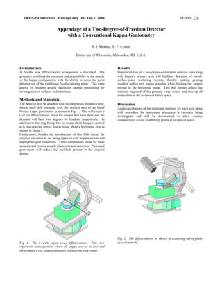
Fig. 2. The diffractometer as shown in scattering out-of-plane
detection mode.