13 down vote One reason we have a tendency to clock flip flops s.pdf
report_2
1. Lab #10 Finite State Machine
Page 1
Abstract
The objective of this lab was to create a finite state machine designed to vend red bull
beverages. The FSM (finite state machine) would keep track of quarters, nickels and dimes
inserted, and would vend a beverage once 75 cents was reached and the vend button was
switched. The customer also had the option of having their coins returned to them at any time by
pressing the coin return switch. A LED would light when the FSM was vending a beverage or
returning coins. An active low reset when depressed would return the value of money back to
zero, and set the next state to idle. The machine had its processes clocked manually but can be
set up to be clocked at a recommended speed of 1 Hz.
The design was tested in a Modelsim test bench. The test bench was written to analyze
waveforms at all important events. These events included the moment reset is depressed, money
increments, transition to enough money state, transition from enough to excess, the vending of a
beverage and coin return. These events are discussed in detail in the results and discussion
portion of the report.
2. Lab #10 Finite State Machine
Page 2
Lab Requirements Summary
The hierarchal design of this lab consisted of two separate entities, the State Machine and
the binary to BCD decoder for the 7 segment displays. The decoder was used in a past
laboratory for much the same purpose: for receiving an 8-bit binary number and turning it into
two separate 7-bit outputs. The design did this by finding the value of the number’s ten’s place
value in binary and outputting that value as a 7-segment display encoded constant. The decoder
would then subtract that value from the entire quantity and the remainder would be decoded to its
7-segment display constant and output to its respective display.
The Finite State Machine design consisted of three separate processes, the synchronous,
combinatorial and output processes. The synchronous process was designed to keep the
transition between states in sync with the clock. It also consisted of an asynchronous active low
reset that would return the FSM to its idle state (wait1). The combinatorial process told the
machine what conditions had to present in order to transition to a particular state. The process
was designed using if statements embedded inside case statements for each individual state.
State Type was the name of the enumerated type which consisted of current_state and
next_state. State type was set to be any one of the eight states (wait1, quarter, nickel, dime,
enough, excess, vend, change). The
next state was dependent on the
inputs of the current state; this is
considered a Moore State Machine.
The combinatorial process told the
FSM what would be the next state
and when that transition would take
place. The synchronous process
used this information to make the
transition at every clock pulse.
Technically the synchronous
process does a state change every
pulse, though that change may be to
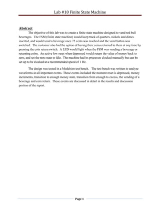
the same as the current state. The
state transition diagram (left) shows
variables that need to be present in
order to instigate a change of state
and to which state.
The output process
controlled the output signals for the
next state. This process was
Image 1: State Transition Diagram
3. Lab #10 Finite State Machine
Page 3
synchronized under the clock and had an asynchronous reset. The reset’s purpose was to set the
outputs to their null values and set the value of money back to zero. The outputs were
synchronized to the clock in order to ensure they changed at the same time as the state.
The FSM starts in the state wait1, if no changes are made to inputs then it can remain in
this state indefinitely. Inserting a coin will transition the machine to the state with the name of
its respective coin (quarter, dime or nickel). These states transition back to wait at the next clock
pulse if there is less than 75 cents counted by the signal: money. If the signal money is equal to
or less than 75 cents at any of these states the machine will transition to the enough state
(meaning enough money is present in the machine for the customer to purchase a beverage). If
the vend button is depressed at this state the machine will move into the vend state and the vend
LED will alight. I the vend state if there is any extra money left over the next transition is to the
change state and the change_back LED will alight. If the money was equal to 75 cents at the
time of the transition from enough to vend the FSM will return to the wait1 state. During the
states wait1, enough or excess the customer can depress the coin_return button and go into the
change state. This will cause the change_back LED to alight and the money count to revert ot
zero. The excess state is reached by inserting a coin once in the enough state. This causes the
FSM to give change back until the value of money is 75 cents. This will also cause the
change_back LED to alight.
Results and Discussion
The results of the lab were determined to be accurate by comparing the waveform outputs
of a test bench to the requirements set forth in the lab. The test bench was used to analyze six
state transitions. The first analyzed was the inserting of coins into the machine. The waveform
below shows 3 coins, a quarter, nickel and dime being inserted. Every rising edge clock pulse
Image 2: Wait1 to Insert Coins State Transition
Where the respective coin input was high received a change to the state of the coin (the quarter,
dime or nickel state). The hex1 and hex0 are signals keeping track of the total amount of change
present (in cents), both outputs go to their own 7-segment display. The translation of the outputs
from their 7-segment display encoding to decimal is equal to the amount of change present in the
machine at that time. The image above shows the value going from: 05 to 15 to 40; this matches
the input of money: nickel plus dime plus quarter.
4. Lab #10 Finite State Machine
Page 4
The next transition analyzed was from the state dime to enough. The change present in
the FSM as shown by hex1 and hex0 (below image) is: 40 to 65 to 75. This corresponds to the
money input of a quarter then a dime.
Image 3: Transition from Dime to Enough
Once the FSM was in the dime state the count of money was equal to 75 cents. This caused the
combinatorial process to choose enough as the next state, this state was achieved by the
synchronous process at the next clock pulse. You can see this by looking at the bottom two
signals: current_state and next_state. Those signals will tell the present state of the FSM and
what the combinatorial process has chosen as the next state.
The next transition analyzed (image below) was from the enough state to excess state.
This was achieved by inserting another dime into the machine. This transition was the next to
take place after the above image’s transition. Once in the “enough state,” once another coin is
Image 4: Transition from Enough to Excess
Inserted into the machine the next state will be excess. The purpose of this state is to ensure the
customer doesn’t overpay for a red bull. Any money over 75 cents is returned to the customer,
the change_led is active (as shown in the image) and the count of money is 75 cents.
5. Lab #10 Finite State Machine
Page 5
The fourth transition analyzed for the lab was from enough to vend. The enough state lets the
machine know enough money is present and to standby to sell a soda (or return the change).
Image 5: Transition from Enough to Vend
Once the customer presses the vend button (get_soda signal in image above) the FSM transitions
to the vend state. In this state the money signal has 75 cents subtracted from it and the vend light
goes active. In the above image exactly 75 cents was in the machine therefore, the next state is
wait1. If there was any left-over change in the machine the next state would be change, the
change light would go active and the money signal would return to zero. As shown in the below
image.
Image 6: Transition from Vend to Change
The final transitory state examined in the test bench was from wait1 to change. The
below image represents the customer pressing the coin_return button and the money signal going
to zero. The 7-segement display outputs shows the change from 65 cents to 0 cents.
Image 7: Transition from Wait1 to Change
6. Lab #10 Finite State Machine
Page 6
The image below is the compilation report with the state machine encoding on auto.
Image 8: Auto State Machine Encoding Compilation Report
18 registers were used in synthesizing the design means the program most likely compiled using
One-Hot Encoding. In this type of state machine encoding there is one register for every flip-
flop. This type of encoding also does not need a decoder which can lessen the complexity of the
design by simplifying addresses. The below image shows the Gray State Machine Encoding.
Image 9: Gray State Machine Encoding Compilation Report
The amount of registers used is only 13 as compared to the 18 of the latter encoding method. In
this type of encoding there is a unique address for each flip-flop used. Starting from 0 and
increasing in one binary increment for each different flip-flop address.
7. Lab #10 Finite State Machine
Page 7
Conclusion
The Moore Finite State machine designed for this lab represented the basic outline of
what a vending machine is designed to do. The machine accurately kept track of the amount of
money, and activated outputs during vending and coin return. These outputs also emulated the
activation of the mechanical apparatus that release the soda and change, although in a much more
simplistic way. The Moore machine was designed to transition to different states based solely
on the current state and its inputs; this in comparison with a Mealy machine which not only relies
on the current state but also on the current inputs.
9. Lab #10 Finite State Machine
Page 9
Image 5: Counter Flag Design
Image 6: Initializing Enable Design
10. Lab #10 Finite State Machine
Page
10
Image 7: Game Controls Design
Image 8: BCD to 7-Segment Display Decoder Design
11. Lab #10 Finite State Machine
Page
11
Appendix B: Source Code
Hierarchal Program Source Code
-- arch.vhd
-- CPET-242 Digital System Design
-- Richard Whitney 4/1/2014
-- This is the hierarchal program for the reaction time game.
Library ieee;
USE ieee.std_logic_1164.all;
Entity arch IS
Port (clock, reset_low, freeze_time : IN std_logic;
set_time
: IN std_logic_vector (7 downto 0);
led_indicator : OUT
std_logic;
second_high, second_low,
milsecond_high, milsecond_low : OUT std_logic_vector(6 downto 0));
End arch;
Architecture behave OF arch IS
Signal flagg : std_logic;
Signal sec_high : std_logic_vector (3 downto 0);
Signal sec_low : std_logic_vector (3 downto 0);
Signal milsec_high : std_logic_vector (3 downto 0);
Signal milsec_low : std_logic_vector (3 downto 0);
Signal init : std_logic;
Signal sec_count : std_logic;
Component sec_counter IS
Port (clk, reset_n : IN std_logic;
second_flag : OUT std_logic);
End Component;
Component counter IS
Port (clk, reset_n : IN std_logic;
second_flag : OUT std_logic);
END Component;
Component game_ctrls IS
Port (flag, clk, reset_n,
key3, enable : IN std_logic;
led_r0 : OUT std_logic;
s1, s0,
m1, m0 : OUT std_logic_vector
(3 downto 0));
End Component;
Component init_en IS
Port (flag, clk, reset_n : IN std_logic;
12. Lab #10 Finite State Machine
Page
12
setter : IN std_logic_vector (7
downto 0);
enable : OUT std_logic);
End Component;
Component bcdtoseg IS
Port (bcd : IN std_logic_vector(3 downto 0);
seg : OUT std_logic_vector(6 downto 0));
End Component;
Begin
eins_flag : sec_counter
Port Map (clk => clock,
reset_n => reset_low,
second_flag => sec_count);
counter_flag : counter
Port Map (clk => clock,
reset_n => reset_low,
second_flag => flagg);
intitialize : init_en
Port Map (clk => clock,
reset_n => reset_low,
flag => sec_count,
setter => set_time,
enable => init);
game_counter : game_ctrls
Port Map ( clk => clock,
led_r0 => led_indicator,
reset_n => reset_low,
flag => flagg,
key3 => freeze_time,
s1 => sec_high,
s0 => sec_low,
m1 => milsec_high,
m0 => milsec_low,
enable => init);
sec_place_high : bcdtoseg
Port Map (bcd => sec_high,
seg => second_high);
sec_place_low : bcdtoseg
Port Map (bcd => sec_low,
seg => second_low);
mil_place_high : bcdtoseg
Port Map (bcd => milsec_high,
seg => milsecond_high);
mil_place_low : bcdtoseg
Port Map (bcd => milsec_low,
seg => milsecond_low);
End behave;
13. Lab #10 Finite State Machine
Page
13
Second Counter Source Code
-- counter.vhd
-- CPET-242 Digital System Design
-- Richard Whitney 3/19/2014
-- Create a VHDL module (entity and architecture) with the following specifications:
--1. It will have two inputs; clk and reset_n and 1 output; second_flag
--2. It should contain two processes
--a. The first process will act as a 1 second timer, resetting itself every second
--b. The second process will use the count from the first process to create a flag (
-- second_flag) every time 1 second has passed. This flag will be the width of a clock pulse.
Library ieee;
USE ieee.std_logic_1164.all;
use IEEE.NUMERIC_STD.ALL;
USE ieee.std_logic_unsigned.all;
Entity sec_counter IS
Port (clk, reset_n : IN std_logic;
second_flag : OUT std_logic);
END sec_counter;
Architecture county OF sec_counter IS
Signal counter : std_logic_vector (27 downto 0); -- counter
signal for second_flag
Constant maxcount : std_logic_vector (27 downto 0) := x"0000002"; -- 50,000,000 Clk cycle count
(1sec)=2FAF080
Begin
Process (clk)
Begin
IF (rising_edge(clk)) Then -- Synchronous counter using
if statement
IF (reset_n = '0') Then -- active low reset
counter <= (others => '0'); -- reset returns internal
counter to
Elsif (counter = maxcount) Then -- maxcount set as constant
counter <= (others => '0'); -- return counter to zero
when maxcount has been reached.
Else
counter <= counter + 1; -- if maxcount has not
been reached increment counter
End IF;
End IF;
End Process;
Process (counter)
Begin
If (counter = maxcount) Then -- whenever counter reaches the maxcount
second_flag <= '1'; -- the second_flag output goes high.
Else
second_flag <= '0';
End IF;
End Process;
End county;
Counter Flag Source Code
-- counter.vhd
14. Lab #10 Finite State Machine
Page
14
-- CPET-242 Digital System Design
-- Richard Whitney 3/19/2014
-- Create a VHDL module (entity and architecture) with the following specifications:
--1. It will have two inputs; clk and reset_n and 1 output; second_flag
--2. It should contain two processes
--a. The first process will act as a 1 second timer, resetting itself every second
--b. The second process will use the count from the first process to create a flag (
-- second_flag) every time 1 second has passed. This flag will be the width of a clock pulse.
Library ieee;
USE ieee.std_logic_1164.all;
use IEEE.NUMERIC_STD.ALL;
USE ieee.std_logic_unsigned.all;
Entity counter IS
Port (clk, reset_n : IN std_logic;
second_flag : OUT std_logic);
END counter;
Architecture county OF counter IS
Signal counter : std_logic_vector (19 downto 0); -- counter
signal for second_flag
Constant maxcount : std_logic_vector (19 downto 0) := x"00002"; -- 500,000 Clk cycle count (10
msec)=7A120
Begin
Process (clk)
Begin
IF (rising_edge(clk)) Then -- Synchronous counter using
if statement
IF (reset_n = '0') Then -- active low reset
counter <= (others => '0'); -- reset returns internal
counter to
Elsif (counter = maxcount) Then -- maxcount set as constant
counter <= (others => '0'); -- return counter to zero
when maxcount has been reached.
Else
counter <= counter + 1; -- if maxcount has not
been reached increment counter
End IF;
End IF;
End Process;
Process (counter)
Begin
If (counter = maxcount) Then -- whenever counter reaches the maxcount
second_flag <= '1'; -- the second_flag output goes high.
Else
second_flag <= '0';
End IF;
End Process;
End county;
Initializing Enable Source Code
-- init_en.vhd
-- Richard Whitney 3/28/14
-- Digital System Design CPET-242
-- This program will count to a time set by a 7 bit input. The program will increment
15. Lab #10 Finite State Machine
Page
15
-- its counter based on a flag from a separate counter program. Once the counter
-- reaches its set time it will set an enable output high.
Library ieee;
USE ieee.std_logic_1164.all;
use IEEE.NUMERIC_STD.ALL;
USE ieee.std_logic_unsigned.all;
USE IEEE.std_logic_arith.all;
Entity init_en IS
Port (flag, clk, reset_n : IN std_logic;
setter : IN std_logic_vector (7
downto 0);
enable : OUT std_logic);
End init_en;
Architecture behave OF init_en IS
Signal int_buff : std_logic;
Signal int : std_logic_vector (7 downto 0);
Signal enable_buff : std_logic;
Signal setter_buff : std_logic_vector (7 downto 0);
Begin
setter_buff <= setter;
Process (clk)
Begin
IF (rising_edge(clk)) Then -- while
rising edge clock and enabling signal (int_buff)
IF (reset_n = '0') Then --
counter will increment until it reaches the time set
int_buff <= '1'; -- by 7
bit input. Each increment happens on a flag that
int <= "00000000"; --can
be varied in time in another program.
enable_buff <= '0'; -- Once
the set time has been reached the counter
ElsiF (flag = '1' and int_buff = '1') Then -- will stop and set an
enable bit high.
IF (int = setter_buff) Then -- Counter can
start again at next reset.
enable_buff <= '1';
int_buff <= '0';
Else
int <= int + 1;
End IF;
End IF;
End IF;
End Process;
enable <= enable_buff;
End behave;
Game Controls Source Code
-- game_ctrls.vhd
16. Lab #10 Finite State Machine
Page
16
-- Richard Whitney 3/28/14
-- Digital System Design CPET-242
-- This design will start a counter and activate an LED once an enable bit input is high.
-- The program will increment its counter (which counts in seconds and milliseconds) every
-- flag from a separate program. The time will freeze once an active low input (key3) is
-- depressed. The program outputs BCD in four separate outputs.
Library ieee;
USE ieee.std_logic_1164.all;
use IEEE.NUMERIC_STD.ALL;
USE ieee.std_logic_unsigned.all;
Entity game_ctrls IS
Port ( flag, clk, reset_n,
key3, enable : IN std_logic;
led_r0 : OUT std_logic;
s1, s0,
m1, m0 : OUT std_logic_vector
(3 downto 0));
End game_ctrls;
Architecture behave OF game_ctrls IS
Signal sec1 : std_logic_vector (3 downto 0); -- Internal buffer signals
Signal sec0 : std_logic_vector (3 downto 0); -- for each clock partition
Signal mil1 : std_logic_vector (3 downto 0);
Signal mil0 : std_logic_vector (3 downto 0);
Signal enable_buff : std_logic;
Signal led_buff : std_logic;
Signal stop_time : std_logic;
Begin
enable_buff <= enable;
Process (clk)
Begin
IF (rising_edge(clk)) Then -- Counter with all
components synchronous.
IF (reset_n = '0') Then --
sec1 <= (others => '0'); -- Active low reset
resets clock to zero
sec0 <= (others => '0'); -- and components
mil1 <= (others => '0'); --
mil0 <= (others => '0');
led_buff <= '0';
stop_time <= '1';
Elsif (flag = '1' and enable_buff = '1' and stop_time = '1') Then
led_buff <= '1';
IF (mil0 = "0001") Then -- if one's
place of second timer is 9
mil0 <= "0000"; -- then
make it 0
mil1 <= mil1 + 1; -- and
increment ten's place of second timer
IF (mil1 = "0001") Then -- if ten's
place of second timer is 5
mil1 <= "0000"; -- then
make it 0
sec0 <= sec0 + 1; -- and
increment one's place of minute timer
17. Lab #10 Finite State Machine
Page
17
IF (sec0 = "1001") Then -- if one's place of
minute timer is 9
sec0 <= "0000"; -- then
make it 0
sec1 <= sec1 + 1; -- and
increment ten's place of minute timer
IF (sec1 = "1001") Then -- if
ten's place of minute timer is 5
sec1 <= "0000";
-- then make it 0
End IF;
End IF;
End IF;
Else
mil0 <= mil0 + 1;
End IF;
Elsif (key3 = '0') Then -- key3 will freeze timer and turn off led
stop_time <= '0'; -- stop time bit goes off and counter stops
counting (freezes)
led_buff <= '0'; -- led indicating reaction timer started
goes off
End IF;
End IF;
End Process;
s1 <= sec1; -- set the outputs to their
s0 <= sec0; -- respective buffer signals.
m1 <= mil1;
m0 <= mil0;
led_r0 <= led_buff;
End behave;
BCD to 7 Segment Display Decoder Source Code
-- bcdtoseg.vhd
-- Richard Whitney 3/28/14
-- Digital System Design CPET-242
-- This program will take a 4 bit input BCD signal and
-- decode it to it's 7 segment display 7 bit output.
Library ieee;
USE ieee.std_logic_1164.all;
Entity bcdtoseg IS
Port (bcd : IN std_logic_vector(3 downto 0);
seg : OUT std_logic_vector(6 downto 0));
End bcdtoseg;
Architecture behave OF bcdtoseg IS
Constant Zero : std_logic_vector (6 downto 0) := "1000000"; -- assigns a constant
value to
Constant One : std_logic_vector (6 downto 0) := "1111001"; -- every possible
output to the
Constant Two : std_logic_vector (6 downto 0) := "0100100"; -- 7 segment display.
Constant Three : std_logic_vector (6 downto 0) := "0110000";
Constant Four : std_logic_vector (6 downto 0) := "0011001";
Constant Five : std_logic_vector (6 downto 0) := "0010010";
18. Lab #10 Finite State Machine
Page
18
Constant Six : std_logic_vector (6 downto 0) := "0000010";
Constant Seven : std_logic_vector (6 downto 0) := "1111000";
Constant Eight : std_logic_vector (6 downto 0) := "0000000";
Constant Nine : std_logic_vector (6 downto 0) := "0010000";
Constant Blank : std_logic_vector (6 downto 0) := "1111111";
Begin
Process (bcd)
Begin
Case bcd IS
When "0000" => seg <= zero; -- Decode the 4 bit input
When "0001" => seg <= one; -- and assign it its
When "0010" => seg <= two; -- respective 7 seg display output.
When "0011" => seg <= three;
When "0100" => seg <= four;
When "0101" => seg <= five;
When "0110" => seg <= six;
When "0111" => seg <= seven;
When "1000" => seg <= eight;
When "1001" => seg <= nine;
When Others => seg <= blank;
End Case;
End Process;
End behave;
Reaction Timer Test Bench Source Code
--*****************************************************************************
--*************************** VHDL Source Code ******************************
--********* Copyright 2010, Rochester Institute of Technology ***************
--*****************************************************************************
--
-- DESIGNER NAME: Jeanne Christman
--
-- LAB NAME: Reaction Timer
--
-- FILE NAME: Reaction_tb.vhd
--
-------------------------------------------------------------------------------
--
-- DESCRIPTION
--
-- This test bench will provide input to test the reaction timer
--
-------------------------------------------------------------------------------
--
-- REVISION HISTORY
--
-- _______________________________________________________________________
-- | DATE | USER | Ver | Description |
-- |==========+======+=====+================================================
-- | | | |
-- | 11/23/05 | BAL | 1.0 | Created
-- | 10/14/11 | JWC | 2.0 | Modified for my lab
-- | | | |
--
--*****************************************************************************
--*****************************************************************************
19. Lab #10 Finite State Machine
Page
19
LIBRARY ieee;
USE ieee.std_logic_1164.ALL;
USE ieee.std_logic_arith.ALL; -- need for conv_std_logic_vector
USE ieee.std_logic_unsigned.ALL; -- need for "+"
ENTITY Reaction_tb IS
END Reaction_tb;
ARCHITECTURE test OF Reaction_tb IS
-- Component Declaration for the Unit Under Test (UUT)
-- if you use a package with the component defined then you do not need this
COMPONENT arch is
PORT (
clock : IN std_logic;
reset_low : IN std_logic;
freeze_time : IN std_logic;
set_time : IN std_logic_vector(7 DOWNTO 0);
--
led_indicator : OUT std_logic;
milsecond_low : OUT std_logic_vector(6 DOWNTO 0);
milsecond_high : OUT std_logic_vector(6 DOWNTO 0);
second_low : OUT std_logic_vector(6 DOWNTO 0);
second_high : OUT std_logic_vector(6 DOWNTO 0)
);
END COMPONENT;
-- define signals for component ports
SIGNAL clock_50 : std_logic := '0';
SIGNAL sys_reset_n : std_logic := '0';
SIGNAL key3 : std_logic := '1';
SIGNAL delay_load_time : std_logic_vector(7 DOWNTO 0) := x"00";
-- Outputs
SIGNAL led_r0 : std_logic;
SIGNAL hex0 : std_logic_vector(6 DOWNTO 0);
SIGNAL hex1 : std_logic_vector(6 DOWNTO 0);
SIGNAL hex2 : std_logic_vector(6 DOWNTO 0);
SIGNAL hex3 : std_logic_vector(6 DOWNTO 0);
-- signals for test bench control
SIGNAL sim_done : boolean := false;
SIGNAL PERIOD_c : time := 20 ns; -- 50MHz
BEGIN -- test
-- component instantiation
UUT : arch
PORT MAP (
clock => clock_50,
reset_low => sys_reset_n,
freeze_time => key3,
set_time => delay_load_time,
--
led_indicator => led_r0,
milsecond_low => hex0,
milsecond_high => hex1,
second_low => hex2,
second_high => hex3
);
20. Lab #10 Finite State Machine
Page
20
-- This creates an clock_50 that will shut off at the end of the Simulation
-- this makes a clock_50 that you can shut off when you are done.
clock_50 <= NOT clock_50 AFTER PERIOD_C/2 WHEN (NOT sim_done) ELSE '0';
---------------------------------------------------------------------------
-- NAME: Stimulus
--
-- DESCRIPTION:
-- This process will apply stimulus to the UUT.
---------------------------------------------------------------------------
stimulus : PROCESS
BEGIN
-- de-assert all input except the reset which is asserted
sys_reset_n <= '0';
key3 <= '1';
delay_load_time <= x"02";
-- now lets sync the stimulus to the clock_50
-- move stimulus 1ns after clock edge
WAIT UNTIL clock_50 = '1';
WAIT FOR 1 ns;
WAIT FOR PERIOD_c*2;
-- de-assert reset
sys_reset_n <= '1';
WAIT FOR PERIOD_c*2;
-- wait for led to turn on
WAIT UNTIL led_r0 = '1';
-- led is now on wait 40 clocks and then assert key3
-- then wait another 100 clocks
WAIT FOR PERIOD_c*1000;
key3 <= '0';
WAIT FOR PERIOD_c*100;
-- reset system and try again
sys_reset_n <= '0';
key3 <= '1';
delay_load_time <= x"05";
WAIT FOR PERIOD_c*2;
-- de-assert reset and wait for led to turn on
sys_reset_n <= '1';
WAIT UNTIL led_r0 = '1';
-- led is now on wait 40 clocks and then assert key3
-- then wait 100 clocks before shutting down simulation
WAIT FOR PERIOD_c*1000;
key3 <= '0';
WAIT FOR PERIOD_c*100;
sim_done <= true;
WAIT FOR PERIOD_c*1
-----------------------------------------------------------------------
-- This Last WAIT statement needs to be here to prevent the PROCESS
-- sequence from re starting.
-----------------------------------------------------------------------
WAIT;
21. Lab #10 Finite State Machine
Page
21
END PROCESS stimulus;
END test;
Appendix C: Timing Diagrams/Waveforms
Image 9: Reset_n First Set to ‘0’
Image 10: Timer Increments From 9 to 10
Image 11: key3 Depressed, LED goes off, Timer Freezes
Image 12: Initializing Timer set to 5 sec, reset_n = '0'
Image 13: Initializing Timer goes to 5 and LED goes on, Game Timer Starts
Counting
Image 14: key3 Depressed, LED goes off, Game Timer froze at 83sec + 10msec