
Recommended
More Related Content
What's hot
What's hot (17)
Similar to Integrated wheelhub technicalpaper-eurobrake2019
Similar to Integrated wheelhub technicalpaper-eurobrake2019 (20)
Recently uploaded
Recently uploaded (20)
Integrated wheelhub technicalpaper-eurobrake2019
- 1. EB2019-MDS-023 DEVELOPMENT OF A WHEEL HUB INTEGRATED BRAKE DISC 1 de la Cruz, Marcelino; 1 Leibl, Raphael*; 1 Raedt, Hans-Willi; 2 Strauß, Wilfried 1 Hirschvogel Automotive Group, Germany; 2 Fritz Winter Eisengießerei GmbH & Co. KG, Germany KEYWORDS – wheel hub, integration, brake disc, lightweight, sportive design ABSTRACT Hirschvogel Automotive Group, together with its cooperation partners from industry, is re- thinking the conventional design of a brake system consisting of friction ring, brake shell, wheel hub and wheel bearing. The current approach is to connect the friction ring directly to the wheel hub by a pot shape. Compared to conventional braking systems, our innovative system is able to transfer higher external loads and save mass at the same time. In addition, it is ensured that the friction ring mounted on the wheel hub can be removed at any time without impairing the dynamic driving characteristics. In order to be able to connect the friction ring directly to the hub, radial arms evenly distrib- uted over the circumference are forged onto the wheel hub. The focus of the development is not only the concept of the radius arms, but also a detachable connection between friction ring and wheel hub. In the design phase, initial brake load scenarios are simulated with simulation tools such as FEM software. The results of these simulations show both in the area of the connection and in the radius arms that the mechanical and temperature-related loads occurring during operation can be endured by the system. The newly developed system features a lower weight compared to conventional brake disc with pot connection to the wheel hub. It will generate lower cost compared to more modern multi-piece brake disc / wheel hub connections. There will be less joining surfaces between wheel rim and wheel hub. The new system will need less assembly space in axial direction. Finally, the filigree structure will provide a sporty, transparent, dynamic look. INTRODUCTION In times of increasing demands with regard to environmental pollution, lightweight design continues to be an elementary goal in the development of new vehicle generations. Nowa- days, more and more developments in the field of drive technology are being pursued, but es- tablished components can also be further developed and sometimes completely disrupted (1). Products from the chassis area are particularly suitable for such innovations, as they represent the unsprung masses (2).
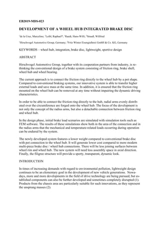
- 2. Figure 1 - left: weight balance of entire vehicle; right: weight balance chassis Optimizing the mass of such components has a positive effect on comfort, but also signifi- cantly reduces fuel and energy consumption in addition to the overall emissions (3). These re- quirements form the basis for the concept of a wheel hub with integrated brake disc. By cooperation of three automotive suppliers, experience in the field of chassis components was combined with brake disc knowledge to create an optimum overall system. STATE OF THE ART In order to understand the development of the new concept, an overview of the relevant com- ponents in the corner module is essential. In the area of the wheel hub, a trend can be ob- served in which an increased integration of single components is taking place and the supply of finished system solutions is preferred by OEMs. An example of this is the development of wheel hub generations shown in Fig. 2. Figure 2 - examples for wheel bearings; left: Generation 1; middle: Generation 2; right: Generation 3 (4)
- 3. The wheel bearing generation 1 represents the simplest system. The rolling bearing is there- fore pressed into the steering knuckle and then the wheel hub into the rolling bearing. Usually the rolling bearing is mounted directly by the OEM. In contrast to the wheel bearing generation 1, the rolling bearing in generation 2 is located in- side the wheel hub. The inner ring of the rolling bearing is mounted onto a stub axle. This process is partly taken over by the OEM. In generation 3, the wheel bearing is connected directly to the wheel hub. The rolling ele- ments of the bearing roll over a part of the wheel hub. The assembly of both components can only be carried out by the bearing manufacturer. In this case the OEM receives a joint system consisting of bearing and wheel hub in finished condition. In the area of brake discs, there is an increasing trend towards lightweight solutions. Such so- lutions are increasingly being adapted to the individual requirements of OEMs. Figure 3 – different types of braking discs; left: standard disc, right: floating disc (5) The designs of existing rotor systems can generally be divided into two categories. Here a dis- tinction is made between a floating and a fixed connection of rotor and brake cup (see Fig. 3). The floating connection is characterized by the decoupling of the rotor from the brake cup. This ensures the temperature-related loads to be separated between the rotor and the cup. Such systems are mainly used in highly motorized vehicles and motor sports. To be more precise, this system allows for radial movement, but circumferential or axial floating is really mini- mal. A fixed connection between the rotor and the brake cup is a cost-effective solution. The brake cup is firmly connected to the rotor. In contrast to the floating alternative, the temperature-re- lated loads are transferred from the rotor to the cup directly. These systems represent the larger quantity of the overall brake discs installed in vehicles (4). In both systems, the brake cup lies on the wheel hub and leads to a material doubling in this area. In addition, when the worn rotor is replaced, the intact brake cup is always disposed un- necessarily.
- 4. The joint development between Fritz Winter Eisengießerei GmbH & Co. KG, NTN-SNR Roulements and the Hirschvogel Automotive Group is presenting an approach that addresses the problems indicated and combines current developments in the area of the wheel hub and brake disc. CONCEPT The basic concept is defining a direct connection between wheel hub and rotor without the brake cup at all. For this a completely new evolution stage of the conventional wheel hub is needed. The following Fig. 4 shows the overall concept: Figure 4 - overall concept Two essential steps must be taken to integrate the rotor with the wheel hub. A certain number of spokes are added to the wheel hub to accommodate the rotor. In return, the rotor loses its previous brake pot shape. The connection between wheel hub and rotor can be with radial movement or fixed according to the requirements. Wheel hub Compared to today's wheel hubs, the newly designed wheel hub not only transmits the brak- ing torque but also plays an additional role: it directly connects to the rotor. The existing brake pot in previous brake components is no longer used in this innovative new develop- ment. For the integration of the rotor, the wheel hub can be extended by any number of spokes on the circumference of the rim mounting surface. These are designed in a way to accommodate the rotor while also guarantee the transmission of torque and force during the braking process.
- 5. Figure 5 - wheel hub; right: stressed wheel hub while braking Simulation tools such as FEM are used to design the connecting elements in order to ensure an optimum distribution of the mass as a function of the occurring stresses. The additional mass on the newly developed wheel hub due to the necessary connecting ele- ments increases the mass compared to conventional wheel hubs. However, there is a signifi- cant mass reduction in total for wheel hubs and brake disc. Rotor The added spokes on the wheel hub make the existing brake cup superfluous. The rotor is at- tached directly to the end of these spokes. With conventional brake systems that also take a brake cup into account, there is a material doubling in the area of the rim mounting (Fig. 6). This doubling can be avoided by supplementing the wheel hub spokes, which results in a fur- ther mass advantage for the overall system. Figure 6 – left: rotor of the new system; right: side view comparison of conventional and new system in the area of the material doubling
- 6. In conventional braking systems, the mechanical load is distributed over a large number of connecting elements between the friction ring and the brake pot during braking. In the new design presented here, this load must be borne by the small number of spokes. For this reason, it is essential during the design phase to make the right choice of material and to optimize the geometry with regard to the loads. Only by this targeted procedure a reduction of the weight can be guaranteed depending on the basic conditions. A typical effect during the deceleration process and the associated temperature load is, for ex- ample, the shielding of the rotor (5). This causes an additional load at braking, which should be avoided in the best case. Such an effect can be largely suppressed by intelligent arrange- ment of the rotor on the wheel hub. This leads both to a reduction in the stress occurring and thus also to a reduction in the mass on the rotor. Connecting parts Figure 7 - connection parts The connection between the friction ring and the wheel hub is made using standard connect- ing elements (Fig. 7). The connection must be designed according to the requirements of the type of connection (floating or fixed) of the brake system. In the simplest cases, standard fit- ting bolts can be used for this, up to more complex systems consisting of a screw-spring-sheet metal combination. CONCLUSION As a result of the expansion of the wheel hub to include the function of the previous brake cup, significant improvements can be achieved in the Corner Module. While the mass of the wheel hub increases due to the additional spoke geometry, the total weight decreases due to the elimination of the brake cup. Thus, a mass advantage of up to 10% per wheel can be achieved in the system under current consideration. Any shielding effects resulting from high temperature loads can be minimized by an optimized connection between friction ring and wheel hub. The new design enables a change of only the wear area of the brake disc and saves valuable resources. In addition, the new wheel hub generation has a transparent and sportier look than conventional systems.
- 7. REFERENCES (1) Wurm T., Busse A., Raedt H. W., “The Lightweight Forging Initiative”, ATZ world- wide, 121(3), 16-21, 2019 (2) Füllgrabe F., “Neue Konzepte für Leichtbau-Bremsscheiben auf Basis metallischer Werkstoffe”, VDI Verlag, 2013 (3) VDA – Verband der Automobilindustrie, “Handeln für den Klimaschutz – CO2 Re- duktion in der Automobilindustrie”, 2009 (4) Schaeffler, “Radlager – Technik, Entwicklung und Produktübersicht”, 2017, source: https://www.schaeffler.com/remotemedien/media/_shared_media/08_me- dia_library/01_publications/automotiveaftermarket/brochure_1/down- load_4/saam_3/schaeffler-aftermarket-broschuere-fag-radlager-de-7640.pdf as of March 7, 2019 (5) Brembo, “GT – GTR Turismo, Technical Information”, 2014