Wireless greenhouse environment monitoring through sensors
Precision Cooling System
1. ___________________________________________
# rmpandey@rrcat.gov.in
DEVELOPMENT AND OPERATION OF 65KW CAPACITY PRECISION
COOLING SYSTEM FOR THE INDUS-2 RF CAVITIES
R.M.Pandey#, B.Prasad, G.R. Deshmukh, Ram Bahadur, Sanjay Gupta
Coolant Systems Lab, Accelerator, Raja Rammana Centre for Advanced Technology, Indore, India.
Abstract
The Indus-2 electron synchrotron accelerator RF cavity
body requires a dedicated De-ionised (DI) precision
water-cooling system. The performance of cavity is of
critical importance at accelerator machine. Any change in
temperature causes corresponding change in cavity body
size, indirectly changing its frequency and harmonics.
The proper operation of the accelerator machine requires
precise synchronization of the cavity frequency with
particle revolution.
Two cooling loops are being operated by Low
Conductivity Water (LCW) System to fulfil these
requirements. The RF Cavity HOM coupler and bracket
assembly are being cooled by the central LCW plant with
temperature stability of ±1.0O
C. The RF Cavity body is
provided with a precision cooling system with
temperature stability of ±0.1O
C at any set temperature
from 250
C to 800
C. The plate heat exchanger and three-
way control valve mechanism provides the precision
chilling loop and maintains the process water tank
temperature. The controlled heating system refines the
pipeline thermal losses. The fast-response direct-
immersion RTD temperature sensor provides feedback
signal to Proportional-Integral-Derivative (PID)
controller. Downtime of the precision cooling system for
any reason can result in downtime of entire accelerator,
hence improvement has been carried out. In this paper,
the development of precision cooling chillers system,
instrumentation, hydraulic manifold and improvement in
operational reliability is elaborated.
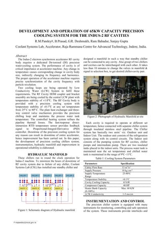
HYDRAULIC MANIFOLD
These chillers run in round the clock operation for
Indus-2 machine. To minimize the hours of downtime of
RF cavity system due to failure of any chiller, Coolant
Systems Lab (CSL) has installed one standby chiller and
Figure 1: Schematic diagram of Hydraulic manifold
designed a manifold in such a way that standby chiller
can be connected to any cavity. Also group of two chillers
and cavities can be interchanged with each other. It takes
less than 10 minutes to change the valves in manifold &
signal in selection box, to get desired chiller-cavity pair.
Figure 2: Photograph of Hydraulic Manifold at site
Each cavity is required to operate at different set
temperature, hence connected with separate chiller system
through insulated stainless steel pipeline. The Chiller
system has basically two units’ viz. Outdoor unit and
Indoor Unit. The outdoor unit consists of the refrigeration
system along with its control circuits. The Indoor unit
consists of the pumping system for RF cavities, chiller
pumps and intermediate pump. There are two insulated
tanks placed in the indoor units. The process water tank is
maintained near the set temperature and chilled water
tank is maintained in the range of 9ºC~11ºC.
Table 1: Cooling System Parameters
Parameters Specification
Cabity Flow Rate 13 m3
h-1
Supply Pressure 10 kg cm-2
Supply Temperature
Range
25-80o
C
Temperature Stability ±0.1o
C
Cavity Cooling Capacity 65 kW
Compressor Capacity 40 HP
Heater Bank Capacity
(0-100%)
Max. 60 KW
LCW Conductivity 1-5 ms/cm
INSTRUMENTATION AND CONTROL
The precision chiller system is equipped with many
instruments for monitoring, controlling and safe operation
of the system. These instruments provide interlocks and
2. status signals during operation of the system. The Unit is
provided with maximum safety and protective devices
including HRC Fuses, Single Phasing Preventer, MCB,
OLR, HP/LP switch, Flow switch, Oil Pressure switch,
electronic protector module, over temperature, dry
run, antifreeze protection etc.
Continuous monitoring of data and logging of them for
their analysis in future is a part of the instrumentation of
this system.
Figure 3: Precision Chiller Indoor Unit with DAQ
Data monitoring can be done remotely also via Ethernet
communication. It improved the daily monitoring of the
critical data and to see the trending. Fault conditions are
visible on computer as well as on local annunciation box
with audio. It improved the fault finding process.
Temperature control is achieved through PID controller
and fast response RTD sensor.
Figure 4: Signal Election Box for cavity selection
Cavity Signal Communication System
All the reference temperature signals from the cavities
are installed in a selector box with silver contact
multiplexing switch. Correct cavity temperature reference
signal is connected to the concerned chiller by using a
selector switch. No physical changeovers of sensors are
required during changing the chiller system with other
standby system. These are the improvements based on our
past experience and we have achieved a great reduction in
chiller shutdown time and ultimately RF cavity operation.
Controls and software
The chillers run unattended round the clock during
Indus-2 operation cycle, hence a DAQ system was
necessary to continuously monitor the system and log the
data. The DAQ system along with software for chiller
management System and alarming system has been
installed. There are safety interlocks, which trip particular
device or whole system if any critical problem appears.
It provides the data in the mimic screen format on the
real time basis. Actual process is shown on the computer
screen in the graphical format and various parameter
values are also shown on the instrument simulated on the
diagram called Cycle Diagram as shown in Fig. 5.
The DAQ System is built around National Instruments
compact RIO (cRIO-9022) controller and distributed I/O
products (24-bit resolution in the range from 4 to 20 mA)
with TCP/IP protocol over standard 100/1000 Ethernet
link. There are 21 analogue signals and 29 digital signals
used in the system.
Figure 5: Cycle Diagram mimic screen where online data
can be monitored of all chillers
All the alarm and trip signals appear on alarm
annunciation panel as well as on computer screen. This is
a server-client based system and remote monitoring is
possible from control room. We can also see history data
for the analysis and fault finding purpose.
Figure 5: Precision Chiller Units in Indus-2 RF area
Temperature Regulation
The plate heat exchanger and three-way control valve
mechanism provides the precision chilling loop and
maintain the process water tank temperature near the set
3. value. The controlled heating system refines the pipeline
thermal losses. The fast-response direct-immersion RTD
temperature sensor has been installed just at the inlet
header of cavity body, which provides feedback signal to
PID controller. The supply water temperature stability
(repeatability) of ±0.1O
C is achieved by the use of
precision and active control system with a tightly
constrained control loop.
Figure 6: Three ways valve performance with RF load
Three-way valve modulates the cooling provided by
primary water to process water inside water-to water Plate
Heat Exchanger (PHE) with reference to error between
set temperature and actual water temperature. The heater
performs fine control of cavity supply temperature and it
keeps on modulating at set temperature to maintain the
stability against thermal load fluctuation during operation.
PERFORMANCE AND RESULTS
The precision chiller system is in operation with Indus-2
RF cavity since 2003 and it is upgraded for DAQ with
standby capacity in 2012. It has provided the required
performance in round the clock operation of Accelerator
machine with high availability.
Figure 7: Chiller performance during Beam Injection,
Ramping & Operation of Indus-2
The temperature of the RF cavity supply water is
maintained within ± 0.1 O
C with respect to set point and
load variation as seen in Fig. 7. The system response
according to change in Beam Energy can also be seen
easily, which clearly talks about the system responsive
nature. When there is substantial change in cavity return
temperature, the variation gets transferred into the system
and tries to unbalance the system. The system counteracts
the changes subjected and maintains the stability.
SUMMARY
The precision cooling system is a cooling station with
heat exchanger between two closed water circuits. The
cavity water flux is always kept constant in any operating
condition. The desired temperature stability is achieved
by regulating the flux of chilled water flow through a heat
exchanger by means of three ways valve through PID
controller and firing of heater bank by thyrister controller.
The supply water temperature stability is achieved by the
use of precision and active control system. The system is
working satisfactorily in round the clock operation with
extreme reliability and ± 0.1 O
C stability at any set
temperature between 25O
C to 80O
C.
REFERENCES
[1] M. Pravin Kumar, Ram Mohan Pandey and Sanjay
Gupta, "Overview of INDUS-2 Cooling System"
InPAC-2003, RRCAT, Indore, February, 3-6, 2003
[2] Ashish Bohrey, M.Lad and P.R. Hannurkar, “Performance of
the frequency tuning system for Indus-2 RF Cavity", InPAC-
2009, RRCAT, Indore, February, 10-13, 2009.
ACKNOWLEDGMENT
Authors would like to thank Shri P.R. Hannurkar, Head
IOAPD Division Raja Ramanna Centre for Advanced
Technology, Indore, for providing continued support and
guidance.