Automatic carbon dioxide methane gas sensor based on the solubility of gases ...
2015 - Senscient Terra Nova - World Oil
1. World Oil®
/ MARCH 2015 61
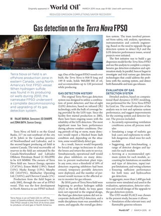
Terra Nova is an oil field 220 mi off the
coast of Newfoundland, discovered in 1984.
The FPSO vessel is the first of its kind used
to produce oil and gas in North America.
REDUCED EMISSION COMPLETIONS/VAPOR RECOVERY
GasdetectionontheTerraNovaFPSO
Terra Nova oil field is an
offshore production zone in
eastern Canada, using North
America’s first FPSO vessel.
When hydrogen sulfide
was found in its producing
oil wells during 2010, the
namesake FPSO underwent
a complete decommissioning
and upgrading of its gas
detection system.
ŝŝ RAJAT BARUA, Senscient, ED SHARPE
and ZONA BATH, Suncor Energy
Terra Nova oil field is on the Grand
Banks, 217 mi east-southeast of the city
of St. John’s in the Canadian province
of Newfoundland and Labrador, and is
the second-largest producing oil field in
eastern Canada. The total recoverable oil
reserves in the field are estimated by the
Canada-Newfoundland and Labrador
Offshore Petroleum Board (C-NLOPB)
to be 419 MMbbl. The owners of Terra
Nova field are: Suncor Energy, operator
(37.675%); Exxon Mobil (19%); Statoil
(15%); Husky Energy (13%); Murphy
Oil (10.475%); Mosbacher Operating
Ltd.(3.85%);andChevronCanada(1%).
Production from the field began in
early 2002, through the use of an FPSO
vessel. This was the first development
in North America to use FPSO technol-
ogy. One of the largest FPSO vessels ever
built, the Terra Nova is 958 ft long and
149 ft wide, holds 960,000 bbl of oil,
and accommodates up to 120 personnel
while producing.
GAS DETECTION HISTORY
The original Terra Nova gas detection
system was designed to utilize a combina-
tion of point detectors and line-of-sight
(LOS) detectors, based on infrared (IR)
technology, with the bulk of coverage be-
ing provided by the LOS type. Since the
facility first started production in 2002,
there have been ongoing issues with the
reliability of the LOS detectors. The most
significant issue has been performance
during adverse weather conditions. Dur-
ing periods of fog or snow, many detec-
tors would report a blocked beam fault
condition and, depending on the situa-
tion, some would falsely detect gas.
As a result, Suncor would frequently
be forced to assign technicians to clean
the lenses and return the units to service.
Simultaneously, operational staff would
also place inhibitors on many detec-
tors to prevent inadvertent plant trips.
In any zone, once a threshold of 50% of
detectors requiring inhibitors had been
crossed, temporary portable detectors
were deployed, and the number of per-
sonnel would increase in the affected ar-
eas to monitor for gas releases.
By 2010, parts of Terra Nova field were
beginning to produce hydrogen sulfide
(H2S) in the well fluids. As toxic gases
were not expected in the original design,
the fixed gas detection system did not in-
corporate dedicated H2S detection, and a
multi-disciplinary team was assembled to
assess, and upgrade, the overall gas detec-
tion system. The team involved person-
nel from safety, risk analysis, operations,
instrumentation and controls engineer-
ing. Based on the need to upgrade the gas
detection system to detect H2S and the
LOS detector performance issues, several
projects were initiated.
The first initiative was to build a gas
dispersion model for the Terra Nova FPSO
andusethisanalysistocompleteacompre-
hensive gas detection evaluation and opti-
mizationstudy.Inparallel,Suncorbeganto
investigate and trial various gas detection
technologies that could address the prob-
lems with the existing system, and detect
both flammable and toxic gas releases.
EVALUATION OF GAS
DETECTION SYSTEM
Detailed analysis, based on computa-
tional fluid dynamics (CFD) modeling,
was performed for the Terra Nova FPSO
by GexCon. The overall objective of the
analysis was to test and optimize system
performance, and suggest improvements
for the existing system and detector lay-
out. The process included:
• Accurately representing ventilation
conditions across all process mod-
ules
• Simulating a range of realistic gas
leak cases and explosions to estab-
lish dangerous cloud sizes for each
module
• Suggesting, and benchmarking, a
range of detector designs and lay-
outs for each module
• Arriving at a recommended opti-
mum system for each module, ac-
counting for limitations on number
and type of detectors, input/out-
put limitations, and voting schemes
• Ensuring sufficient performance
for both toxic and hydrocarbon
gas detection.
In aggregate, more than 1,400 gas leak
scenarios were simulated and used in the
evaluation, optimization, detector selec-
tion and overall design of the upgrade to
the gas detection system.
The CFD model FLACS was chosen
in the present study, because it allows:
• Simulation of the relevant toxic and
flammable gaseous releases
Originally appeared in World Oil
®
MARCH 2015 issue, pgs 61-68. Used with permission.
2. World Oil®
/ MARCH 2015 63
REDUCED EMISSION COMPLETIONS/VAPOR RECOVERY
• Modeling of the detailed geometry
within the facility
• Simulation of both natural and
forced ventilation within the facility
• Evaluation of gas concentration
measured by line and point detectors
• Evaluation of danger potential for
the dispersion cloud
• Ability to perform parametric sen-
sitivity and optimization studies.
The geometry of the Terra Nova
FPSO was based on a computer-aid-
ed design (CAD) model, as shown in
Fig. 1. The quantitative evaluation of
the GDS in the process modules was
based on testing the performance for a
large set of realistic gas leak scenarios.
This means that ventilation conditions
and gas leak properties had to be mod-
eled as accurately as possible. The local
ventilation conditions were critical in
understanding the formation and migra-
tion of flammable or toxic gas clouds.
The ventilation conditions were deter-
minedbythewindspeedanddirection;the
heading of the FPSO; large-scale effects
from modules and buildings, upwind and
downwindoftheareaofinterest;aswellas
smaller-scale effects from buildings, walls,
equipment and piping inside the area of
interest itself.
SELECTING THE RIGHT
TECHNOLOGY
Sinceitcommencedoperationin2002,
the Terra Nova FPSO has relied primarily
on LOS detection. Therefore, Suncor’s
preferred option was to determine if LOS
technology existed that could replace its
existing detectors and provide coverage
for both flammable and toxic gas leaks.
This would minimize structural modi-
fications required to mount new units,
avoid having to run new cables and trays,
thereby minimizing construction time
and cost. An extensive search eventually
led the Suncor team to lab test, field trial
and ultimately select the Enhanced Laser
Diode Spectroscopy (ELDS) technology.
This technology, developed by Senscient,
had the capability of combining toxic and
flammable gas detection in a single LOS
detector while significantly improving the
performance and reliability of the FPSO’s
overall gas detection system.
In February 2011, a trial ELDS unit
was acquired and subjected to qualifica-
tion testing at the Terra Nova onshore
distributed control system (DCS) simu-
lator. Over a period of two weeks, strin-
gent performance tests were conducted
on the device, under four conditions that
were known to generate problems for the
existing IR detectors:
• Simulated fog, using water mist
• Direct water spray on the device
lenses
• Plastic of various types placed in
the beam path
• Snow placed over the lens (approxi-
mately 1 in. thick).
The test results showed no issue with
performance for all four conditions.
Using a transmitter-receiver configura-
tion, ELDS systems detect and measure
gas concentrations at specific target gas
absorption wavelengths over distances of
up to 655 ft, Figs. 2 and 3. The transmit-
ter uses highly reliable, solid-state, laser
diode sources, similar to those used in
telecommunications applications to gen-
erate a laser beam. The receiver measures
absorbance changes when a combus-
tible or toxic gas passes through the laser
beam. One of the key techniques that
enables ELDS to detect a small fractional
absorbance, and eliminate a false alarm,
is harmonic fingerprinting. A harmonic
fingerprint is a specific set of harmonic
components introduced by target gas ab-
sorption, where the relative amplitudes
and phases of the components are known
and specific to the target gas absorption
line that is being scanned.
Using a small, retained sample of tar-
get gas inside the transmitter, the tem-
perature and wavelength modulation
currents applied to the transmitter’s laser
diodes are actively controlled to lock the
lasers, such that absorption by target gas
produces specific harmonic fingerprints.
The relative amplitudes and phases are so
unique that only absorption by the speci-
fied target gas produces a signal with the
desired harmonic fingerprint. Noise ab-
sorption by atmospheric gases, and co-
herent interference effects, never produce
signals with the harmonic fingerprint,
enabling an ELDS-based gas detector
to eliminate false alarms. In addition to
maintaining a harmonic fingerprint lock,
the gas reference cell enables remote, on-
command, electronic functional testing of
the gas detector, either locally or from the
control room under any condition.
In the test, the transmitter simulated
a predefined quantity of target gas by di-
recting the laser beam through the refer-
Fig. 1. A graphical illustration of the Terra
Nova FPSO indicating key areas and
modules.
Fig. 2. ELDS systems use a transmitter-receiver configuration to detect and measure gas
concentrations at specific target gas absorption wavelengths, over distances of up to 655 ft.
Fig. 3. ELDS systems installed in field operations.
3. World Oil®
/ MARCH 2015 65
REDUCED EMISSION COMPLETIONS/VAPOR RECOVERY
ence cell. ELDS units are programmed to
conduct a validity test every 24 hr. The
results of detector functionality testing
are gathered and logged automatically.
The presence of a gas reference cell is
an innovation that improves reliability
and reduces maintenance, which elimi-
nates the need for technicians to carry
cylinders of hazardous gases through the
FPSO to test gas detectors.
IMPLEMENTATION OF THE
RETROFIT AND UPGRADE
Once onshore testing was done, a
dual, methane-H2S ELDS detector was
installed in May 2011, replacing an is-
sue-prone IR LOS device. The distance
between the transmitter (Tx) and re-
ceiver (Rx) for this installation was ap-
proximately 112 ft. During a trial period
that lasted approximately 24 months,
the ELDS detector performed very well,
with zero spurious trips. The only issue
identified was a loose mounting bracket
that resulted in misalignment. Following
the successful offshore trial, a decision
was made by Suncor to replace all exist-
ing IR LOS gas detectors on the Terra
Nova FPSO with the ELDS technology.
In aggregate, 141 IR LOS detectors were
slated for replacement. A recommenda-
tion from the study by GexCon added
another 17 ELDS detectors to provide
for additional coverage. Therefore, the
overall retrofit and upgrade plan called
for the decommissioning of 141 IR LOS
detectors and the installation of 158
ELDS detectors.
Retrofitting the FPSO, while it was
on location, in full operation, required
significant planning. A thorough work
package was developed which provided
a plan for the decommissioning of the
existing IR detectors, installation of the
new ELDS detectors, and training of per-
sonnel. Change out of the LOS detectors
commencedin2013.AsofJuly2014,78of
158 ELDS detectors were installed, with
the remaining devices scheduled to be
changed through the remainder of 2014
and into 2015.
RESULTS AND DISCUSSION
The performance of the upgraded sys-
tem has been exceptional. Prior to the up-
grade, the FPSO experienced three to five
plant trips, more than 100,000 fault indica-
tions, and 20 to 25 unrevealed failures per
year. Statistics from the FPSO data histo-
rian, maintenance management system,
and lost production
tracking register
were analyzed to
quantify this perfor-
mance.
IMPACT ON
SAFETY
PERFORMANCE
A review of the
maintenance man-
agement system
showed that there
was an average 21
unrevealed gas de-
tector failures per
year from 2009 to
2013. The signal
that these IR de-
vices were sending
to the control sys-
tem indicated full health. However, they
failed to respond to a function check.
The ELDS detectors address this prob-
lem by completing a daily diagnostic
check and signaling a fault, if there is an
issue. As of Dec. 31, 2014, the FPSO had
not recorded a single unrevealed failure
with the laser-based gas detectors. Start-
up and shutdown of a facility introduce
risks that are not present when a plant is
in steady-state operations. By reducing
the number of spurious trips, the time
spent in start-up or shutdown modes is
reduced, thereby decreasing the risk to
the facility.
The laser-based sensors installed
on the FPSO have a minimum detec-
tion threshold that is much lower than
the older IR-based detectors. Instead of
a hydrocarbon detection threshold of
1 LELm/2.5 LELm (low/high alarm),
the laser-based detectors can be set to a
threshold of 0.2 LELm/1 LELm (low/
high alarm), without experiencing any
drifting and related spurious alarms. The
effect of this five-fold increase in sensitiv-
ity is that the detectable volume of any gas
cloud is larger. Figure 5 shows two plots
of the same simulated gas leak. The red
zone is flammable gas, whereas the yel-
low zone represents detectable volume
with a sensitivity of 10% LEL and 50%
LEL, respectively for the top and bottom
plots. Increasing the sensitivity of detec-
tors increases the detectable volume and
makes it more likely that any given detec-
tor will be exposed to detectable gas be-
fore the flammable volume reaches a dan-
gerous size, Fig. 4. Furthermore, the H2S
content on the FPSO means even small
leaks can be hazardous, thus, increased
sensitivity is an important tool to ensure
worker safety.
A comprehensive dispersion analysis
based on worst-case H2S concentrations in
the production stream was performed for
the entire FPSO. This study revealed that
hazardous levels of H2S could occur in the
port half of module M04, the area of the
process facility where regeneration of gly-
col and treatment of gas and produced wa-
tertakesplace.ForotherareasoftheFPSO,
results obtained from the gas dispersion
modeling demonstrated that the H2S con-
centrations were low, and, thus, detection
was adequately ensured via the optimized
hydrocarbon GDS. Consequently, a dedi-
cated H2S detection system was developed
and installed in the M04 module with
laser-based LOS devices. The installed sys-
tem satisfied the performance criteria for
H2S detection.
Fig. 4. Illustration of a gas release simulation resulting in a
hazardous flammable cloud scenario (1,250 m3) in the power
generation module (M09). Concentration contours from 50%
LEL (lower explosive limit) depicted in deep blue, to UEL (upper
explosive limit) depicted in dark red, are shown.
Fig. 5. Flammable and detectable volumes
for a simulated gas leak scenario for two
different detection thresholds.