2. M. Divya et al. / Journal of Materials Processing Technology 211 (2011) 2032–2038 2033
Table 1
Composition of ER410NiMo weld metal in wt%.
Elements C Cr Ni Mn Mo P S Si V Co Cu Sn Creq Nieq
Wt % 0.02 12.5 5.0 0.45 0.50 0.025 0.045 0.40 – – 0.32 – 13.6 5.8
Table 2
Welding parameters used for preparation of weld pads.
Current (A) Voltage (V) Heat input
(kJ/mm)
Shielding gas Preheat
temperature, ◦
C
Interpass
temperature, ◦
C
Post heating,◦
C PWHT
50–60 12 1.1 99.99% argon 250 200 250 (15 min) 650 ◦
C/2 h + 600 ◦
C/4 h
The objective of the present study is to choose first stage PWHT
temperature just above Ac1 temperature and second stage just
below Ac1 temperature. This was required because instability of
austenite increase with increase in temperature and very low tem-
perature below Ac1 is not adequate to temper the martensite. Very
poor toughness ∼13 J has been reported by Das et al. after 675 ◦C/2 h
and 615 ◦C/4 h heat treatment (Das et al., 2008). In spite of two stage
PWHT, presence of retained austenite in the weld metal influences
toughness of the weld metal. This aspect has not been addressed
adequately in any literature. Thus, a judicious selection of first stage
PWHT temperature just above the Ac1 temperature of the alloy and
time is required to derive the full benefits of reverted austenite
formed during the PWHT. The paper describes a study on welding
procedure qualification for welding 414 martensitic stainless steel
turbine shroud with ER 410NiMo filler wire and selection of appro-
priate PWHT temperatures to ensure good toughness of the weld
metal.
2. Experimental
Elemental composition of ER 410NiMo weld metal employed in
the present study is given in Table 1. In order to choose the appro-
priate temperatures of PWHT, Ac1 temperature of the weld metal
was determined experimentally. For this purpose filler wire was
deposited on a steel plate using GTAW process. This weld metal
deposit was first given a solutionizing heat treatment at 1000 ◦C/1 h
followed by air cooling. Subsequently, specimens extracted from it
were subjected to tempering in the temperature range 450–825 ◦C
for 1 h at each temperature. Subsequently, the hardness of the weld
metal was measured using Vickers hardness tester and values were
plotted as a function of tempering temperature. The temperature
that gives minimum hardness and above which hardness increases
with increase in tempering temperature is chosen as Ac1 tempera-
ture.
A weld pad was prepared using Gas Tungsten Arc Welding
(GTAW) process with12 mm thick AISI 410 stainless steel plate
and 410NiMo consumable using the welding parameters given in
Table 2 for evaluation of weld metal toughness. Another weld pad
was prepared using pieces from the original shroud piece that was
employed for repair welding and 410NiMo consumable. The weld-
ing process and parameters employed were same as those used
for the weld pad prepared for toughness evaluation. This weld pad
was used for tensile and bend tests during the procedure quali-
fication. After completion of the two stage PWHT, the weldments
were subjected to radiographic examination and found to be defect
free. Metallographic specimens were prepared from the welds after
first and 2nd stage heat treatments using standard grids of emery
papers for grinding and diamond slurry of 0.25 m for final pol-
ishing. Specimens were etched using Villela’s reagent and were
examined using optical and scanning electron microscope (SEM).
Energy dispersive spectra (EDS) were taken at different locations on
the specimens and variation in the composition was studied assum-
ing that weld metal is essentially a Fe–Cr–Ni alloy. Hardness of
the weld metal was measured using Vickers hardness tester. Weld
metal was examined for retained austenite using X ray diffraction
(XRD) technique which was carried out using a Fe-K␣ radiation for
the 2Â range 40◦–120◦ in step interval of 0.01◦.
Flat, sub size cross weld tensile specimens of dimension
100 × 10 × 3 mm, gauge length 25 mm and L0/
√
A0 = 4.5 and bend
test specimen of size 100 × 20 × 3 mm3 were fabricated from the
weld pad prepared in the laboratory using shroud piece and the
ER 410NiMo filler wire. The room temperature transverse tensile
and bend tests were carried out for the weldments as per ASTM
practice E8-04 (American Standards, 2009) and ASTM practice E
190-92 (American Standards, 2008) respectively after the PWHT.
The strain rate employed for the tensile test is 3.3 × 10⁻⁴ s−1. The
full size cross weld Charpy impact specimens were prepared from
the weld pad prepared from 12 mm thick 410 martensitic stainless
steel plates with the notch in the weld metal along the welding
direction. Charpy impact tests were conducted at room tempera-
ture and fracture surfaces of the specimens were examined using
scanning electron microscope (SEM).
After successful completion of the repair welding procedure, the
shroud piece subjected to mock up welding was used for metallog-
raphy and hardness measurements. Microstructure was examined
using optical microscope and SEM.
2.1. Results
2.1.1. Ac1 temperature for weld metal
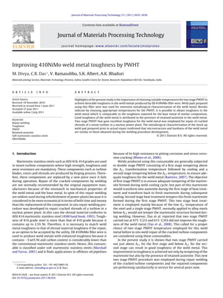
The variation of hardness of the weld metal with tempering
temperature for fixed duration of 1 h is shown in Fig. 1. Hard-
ness of the as welded sample was 450 VHN and it decreased to
Fig. 1. Hardness variation with tempering temperatures for 410NiMo filler wire.
3. 2034 M. Divya et al. / Journal of Materials Processing Technology 211 (2011) 2032–2038
Fig. 2. Microstructures of the samples tempered at (a) 600 ◦
C/1 h (b) 650 ◦
C/1 h
(c)700 ◦
C/1 h.
390 VHN on tempering at a temperature of 450 ◦C. Thereafter, it
decreases with increase in tempering temperature and a minimum
value for the weld metal is obtained for the tempering temperature
of 630 ◦C. Beyond this temperature, hardness increases again and
this increase is due to transformation of austenite formed during
heat treatment to fresh martensite on cooling, Fig. 2(a–c) shows the
microstructures of samples tempered at 600, 650 and 700 ◦C. The
microstructure of sample tempered at 600 ◦C shows fully tempered
martensite whereas the sample tempered at 650 and 700 ◦C shows
a mixture of tempered and freshly formed martensite. The amount
of fresh martensite present in the sample tempered at 650 ◦C is
less compared to that present in the sample tempered at 700 ◦C.
Tempering kinetics of the martensite formed after the solutionizing
heat treatment increases with temperature and maximum temper-
Fig. 3. Microstructure of 410NiMo weld metal after two stage PWHT.
ing occurs just below the Ac1 temperature (Qin et al., 2008). Hence,
630 ◦C, is close to the Ac1 transformation temperature for the weld
metal which suggest that the first stage PWHT temperature 650 ◦C
is above and second stage PWHT temperature 600 ◦C is below this
temperature.
2.1.2. Microstructure and microchemistry
Microstructure of the weld metal after the two stage PWHT is
shown in Fig. 3. The structure is typically tempered martensite and
the prior austenite boundaries are clearly discernable. A high mag-
nification SEM micrograph of the same weld is shown in Fig. 4.
Figure reveals an aligned second phase structure within the prior
austenite grains. This is different from what is generally observed in
classical tempered martensitic steel. Microstructure at still higher
magnification (shown in the inset of Fig. 4) shows microstructure
essentially consists of two separate phases. Microstructure of the
weld after first stage of heat treatment is shown in Fig. 5. This also
reveals aligned second phase structure as in Fig. 4, though there is
some difference in the morphology of the two phases.
SEM/EDS spot analysis was done on different locations on
the microstructure to determine if any elemental segregation is
present. As the width of the aligned phase is in submicron levels,
a clear evidence of alloy partitioning could not be obtained. How-
ever, this analysis, carried out arbitrarily on the bulk weld metal in
the as welded, after first and two stage heat treatments revealed
that scatter band for Ni content increased progressively from the
Fig. 4. SEM image of weld metal subjected to two stage PWHT
(650 ◦
C/2 h + 600 ◦
C/4 h).
4. M. Divya et al. / Journal of Materials Processing Technology 211 (2011) 2032–2038 2035
Table 3
EDS results of 410MiMo weld metal.
Elemental composition (wt%) Cr Ni
min max SD min max SD
As welded condition 13.0 13.6 0.3 4.7 4.9 0.1
After first stage PWHT (650 ◦
C/2 h) 12.2 13.6 0.7 4.3 5.7 0.7
After two stage PWHT (650 ◦
C/2 h + 600 ◦
C/4 h) 12.6 13.4 0.4 3.8 5.8 1
as-welded condition to that after two stage heat treatment. Results
of estimation of Cr and Ni content in the weld metal from 25 mea-
surements done arbitrarily on the bulk weld metal in each of the
heat treatment conditions is given in Table 3. In the as-welded con-
dition, the scatter band for variation of Ni content is only 0.1 wt.%
and it increased to 0.7 wt.% after the first stage heat treatment and
then to 1.0 wt.% after the two stage heat treatment. In contrast,
variation in the scatter band for Cr content was less with no def-
inite trend with heat treatment. Further, average composition of
both Cr and Ni remained more or less unchanged with heat treat-
ment condition. These results indirectly indicate there is some alloy
partitioning between the two phases during heat treatment.
2.1.3. X ray diffraction (XRD)
XRD of the weld metal after first stage and two stage heat treat-
ment was carried out to identify the phases and the result shown in
Fig. 6 clearly indicates that in addition to tempered martensite, the
weld metal contains retained austenite. The weld metal in the as
welded condition revealed only martensite but no retained austen-
ite. The volume fraction of retained austenite was calculated from
the X- ray diffraction pattern using Eq. (1) (Cullity, 1978), which
relate integrated intensity of austenite and ferrite peaks to the vol-
ume fraction of the respective phases.
I (hkl)
I˛
=
R (hkl)
R˛ (hkl)
×
V
V˛
(1)
I (hkl) and I˛ (hkl) are the integrated intensity from a given plane
(h k l) of austenite and martensite (or ferrite) phase respectively.
V and V˛ are the volume fractions of austenite and martensite
respectively, and R factor is calculated separately for austenite and
martensite phase as R (hkl) and R˛ (hkl) respectively and are given
for a specific peak by Eq. (2).
R =
1
v2
F
2
(p)(Lp) e−2m
(2)
R factor depends on Â, h k l and kind of substance. Its cal-
culation requires knowledge of crystal structures and lattice
Fig. 5. SEM image of weld metal subjected to first stage PWHT (650 ◦
C/2 h).
parameters of both the phases, where, v= volume of unit cell,
F = structure factor, p = multiplicity factor, Lp = Lorentz-polarization
factor, e−2m = temperature factor. The values for these parameters
used for the calculation of volume fraction of retained austenite are
listed in Tables 4a and 4b. The volume fraction of retained austenite
was estimated to be 27% and 17% after the first stage PWHT and two
stage PWHT, respectively assuming that only austenite and ferrite
(tempered martensite) phases are present in the weld metal.
From the XRD profiles, it is clear that, retained austenite is
present in the weld metal after first and two stage heat treatments.
2.1.4. Mechanical properties
The hardness of the weld metal in the as welded condition
was 450 VHN indicating that the microstructure is predominantly
martensite. After the first stage heat treatment, it is reduced to 340
VHN, and at this stage the microstructure is a mixture of martensite
and tempered martensite with some retained austenite. Hardness
of the weld metal after two stage heat treatment is only 250 VHN
showing significant tempering of the martensite after two heat
treatments.
Yield strength (YS) and ultimate tensile strength (UTS) obtained
from cross weld tensile samples were 655 MPa and 780 MPa,
respectively. With total elongation of 17.5%, the weldment exhib-
ited good ductility and location of failure was outside the HAZ close
to the unaffected base metal. Results of the impact test carried out
at ambient temperature (∼24 ◦C) showed that the weld metal after
two stage heat treatment possessed excellent toughness with a
Charpy impact test value of 179 J. This value is significantly higher
Fig. 6. XRD pattern obtained from the sample subjected to single stage and two
stage PWHT.
5. 2036 M. Divya et al. / Journal of Materials Processing Technology 211 (2011) 2032–2038
Table 4a
Parameters used for calculation of R␥-factor for calculation of volume fraction of retained austenite.
PWHT R␥ factor Volume of unit cell
(v) ×10−30
m3
Structure factor
(F)
Multiplicity
factor (p)
Lorentz
polarization factor
(Lp)
Temperature
factor (e−2m
)
650 ◦
C/2 h 191.87 42.5 4084.03 8 11.13 0.957
650 ◦
C/2 h + 600 ◦
C/4 h 83.515 49.02 3673.19 8 7.2 0.960
Table 4b
Parameters used for calculation of R␣-factor for calculation of volume fraction of retained austenite.
PWHT R␣ factor Volume of unit cell
(v) ×10−30
m3
Structure factor (F) Multiplicity factor
(p)
Lorentz polarization
factor (Lp)
Temperature factor
(e−2m
)
650 ◦
C/2 h 255.1 21.7 1000.01 12 10.617 0.955
650 ◦
C/2 h + 600 ◦
C/4 h 116.28 23.6 878 12 6.521 0.957
than the impact toughness values reported (150 J) for the weld met-
als of ER 410NiMo consumables. Fractographs of Charpy impact test
specimens taken from the stretch zone and middle of the sample
is shown in Fig. 7. The figures show that the fracture mode is quasi
cleavage in the stretch zone and ductile in the centre region. The
dimples in the ductile regions are oriented along the direction of
crack propagation.
Considering the fact that achieving good toughness comparable
to that of base metal is difficult in weld metal, possible reasons for
such a good toughness, better than that reported by Blimes et al. in
literature (Blimes et al., 2001), are being presented in the discussion
section.
Fig. 7. Fractographs of impact tested sample: (a) stretch zone and (b) middle zone.
3. Discussion
ER 410NiMo weld metal is normally classified as soft marten-
sitic stainless steel because of low carbon content. However, due
to fairly high Ni content in the alloy, the weld metal in the as-
welded condition can have some retained austenite. This is because
Ni significantly lowers the Ms temperature of the steel. Zaslavskaya
et al. (1973) have reported that in Cr–Ni steels, every one percent
addition in Ni content lowers the Ms temperature by 57 ◦C. Ms tem-
perature estimated from the chemical composition using empirical
equation given in Eq. (3) (Marshall and Farrar, 2001) is 194 ◦C. Con-
sidering the difference in Ms and Mf temperature is ∼200 ◦C (Béres
et al., 2001), Mf would be below 0 ◦C which suggest when weld
metal cools down to room temperature, which is typically ∼30 ◦C,
the martensitic transformation is not complete and the weld metal
contain some retained austenite (Marshall and Farrar, 2001).
Ms (◦
C) = 492 − 125 (wt%C) − 65.5 (wt%Mn) − 10(wt%Cr)
− 29(wt%Ni) (3)
From the tempering behavior of the weld metal shown in Fig. 1,
it is clear that the Ac1 temperature for the weld metal is close to
630 ◦C. Hence the temperatures selected for the first and second
heat treatments are just above and below this temperature. During
the hold time of this heat treatment fresh austenite will be formed
and the volume fraction of austenite will be dictated by thermody-
namic equilibrium of the phases at the heat treatment temperature.
As this temperature is just above Ac1 for this alloy, volume fraction
of austenite would not be very high. However, it is possible that
alloy partitioning between the austenite and the martensite, which
undergoes tempering, can take place during this heat treatment. Ni
which is an austenitic stabilizer can diffuse in to austenite and Cr, a
ferrite stabilizer can increase in tempered martensite. However, as
the volume fraction of austenite is significantly lower than that of
the tempered martensite, increase in Ni content in austenite would
be more than increase in Cr in ferrite. Further Cr will also form car-
bides. This argument is in agreement with Leem et al. (2001) who
reported that for a 13 Cr steel of similar composition decrease in
Ni content is accompanied by almost no variation in Cr content in
the austenite formed during hold time at temperatures above Ac1.
Increase in the scatter band for Ni content in the matrix from 0.1
to 0.7 wt.% is an indirect evidence of Ni enrichment in the austen-
ite. Ni enrichment in the austenite results in further decrease of Ms
and Mf temperatures. This means at the end of first stage of heat
treatment, the weld metal will have some retained austenite which
was absent in the as-welded condition, which was confirmed from
XRD result. XRD results clearly confirm the presence of retained
austenite in the weld metal after this heat treatment. The vol-
ume fraction of retained austenite after reversion heat treatment
6. M. Divya et al. / Journal of Materials Processing Technology 211 (2011) 2032–2038 2037
at room temperature is proportional to volume fraction of reversed
austenite formed at the heat treatment temperature and stability
of the austenite as described by Leem et al. (2001). Stability of the
austenite increases with increase in Ni content in austenite, which
in turn depends on the heat treatment temperature and volume
fraction of the reversed austenite formed. With increase in temper-
ature above the Ac1, the volume fraction of the reversed austenite
increases. However, it has been shown by Leem et al. that Ni con-
tent in the austenite would decrease which would in turn decrease
the stability of the austenite. Thus, it has been shown that there
is an optimum heat treatment temperature above the Ac1 that can
result in highest volume fraction retained austenite in the alloy.
It has to be noted that the fresh martensite formed during cool-
ing part of this heat treatment will have more Ni than the tempered
martensite, the major phase present in the weld metal. The Ac1
temperature of this Ni enriched fresh martensite as well as the
retained austenite would be lower than that of the bulk compo-
sition (∼630 ◦C). If this temperature is below 600 ◦C, then, the fresh
martensite formed during cooling after first stage heat treatment
would transform to austenite during the hold time of second stage
of PWHT carried out at 600 ◦C. Hence, at the end of the hold time
of the 2nd PWHT, there will be substantial volume fraction austen-
ite (both retained after the first heat treatment and fresh formed
by reversion of the martensite). As a result, at the end of this heat
treatment also some austenite will be retained. However, as the
heat treatment temperature is low and austenite formed by rever-
sion is also low, the volume fraction of retained austenite formed
after this heat treatment is lower than the first stage. This is in
agreement with results obtained from XRD.
Many authors have reported that presence of substantial volume
fraction of retained austenite in the 410NiMo weld metal has a sig-
nificant role in improving the toughness of the weld metal (Blimes
et al., 2001). Blimes et al. have reported that ductile austenite phase,
present as thin film along the interlath boundaries effectively slows
down the crack propagation and absorbs most of the energy by
transforming into martensite due to the plasticity at the crack tip
and thus contribute to the toughness of the weld metal. This is sim-
ilar to the mechanism of toughening reported in the case of TRIP
steels (Antolovich and Singh, 1971). Impact toughness reported is
after two stage heat treatment. Volume fraction of retained austen-
ite found to be lower after this two stage heat treatment than that
obtained after the single stage. However, two stage heat treatment
is necessary to temper the fresh martensite formed during the first
stage.
The above discussion clearly indicates that in addition to tem-
pering of the martensite during PWHT, retained austenite present
in the weld metal at the completion of two stage heat treatment
also contribute to the very good toughness obtained for the weld
metal. If that is so, one should be able to explain why the tough-
ness for the same weld metal subjected to two stage heat treatment
at 675 ◦C/2 h and 615 ◦C/4 h is poor. It has been shown by Leem
et al. (2001) that with increase in temperature above Ac1, the vol-
ume fraction of the retained austenite would decrease because the
stability of the austenite formed by reversion during heat treat-
ment decreases. This is because Ni content in the reverted austenite
decreases with increase the volume fraction of the austenite. As a
result, even though volume fraction of the reverted austenite would
be high, most of it would be transformed into martensite, thus
reducing the volume fraction of the retained austenite. It is also
argued that defect density increases exponentially with increase
in the heat treatment temperature and this can also accelerate the
transformation of the austenite to martensite. Hence, the effect of
increasing heat treatment temperature much beyond the Ac1 tem-
perature is to reduce the volume fraction of the retained austenite
at the end of the heat treatment. Eun Seo Park et al. (2004) have also
reported that volume fraction of retained austenite decreases with
Fig. 8. Schematic representation of turbine blade with shroud.
increase in tempering temperature beyond 650 ◦C. As observed in
the present study, the second stage heat treatment would further
bring down the volume fraction of the retained austenite. Hence,
the large improvement achieved in the toughness of the weld metal
in the present study from that reported earlier could be attributed
to difference in the choice of the heat temperatures in these two
cases.
It may be mentioned that toughness obtained in the 410NiMo
weld metal after this two stage PWHT is higher than the reported
by others (Blimes et al., 2006) even though the volume fraction of
retained austenite in the present study is lower than that reported
by them for the same material. Reasons for this are not clear. It could
be mentioned that in addition to volume fraction, morphology and
distribution of retained austenite may also be contributing to the
toughness. Further studies involving detailed microstructural char-
acterization of the weld metal would be required to understand the
role of retained austenite in improving the toughness of the weld
metal in more detail.
4. Implementation
Having demonstrated that toughness of the weld metal can
be matched with that of the shroud material of the turbine by
proper choice of welding consumable and two stage heat treat-
ment, in situ weld repair of the cracked shroud material was taken
up. The cracked portion of the shroud was removed by cutting and
new shroud piece was welded to the existing shroud by GTAW
process using ER 410NiMo filler wire. A mock up welding was car-
ried out prior to actual repair welding to replicate the constraints
present in the turbine component and to demonstrate that both
repair welding and subsequent PWHT can be carried out under such
constraints. The welding parameters and PWHT used for actual
repair and mock up procedures are the same as described in this
study. Fig. 8 shows a schematic representation of the turbine blade
with shroud and tenon head. The mock up weld was subjected to
microstructual examination and hardness measurement to confirm
that the properties of the repair weld is similar to those obtained
for the laboratory welds.
7. 2038 M. Divya et al. / Journal of Materials Processing Technology 211 (2011) 2032–2038
Fig. 9. Microstructure of 410NiMo weld metal taken form mock up weld metal using
(a) optical microscope and (b) SEM.
The optical and scanning electron microscopy images of the
weld metal microstructure of the mock up weld are shown in Fig. 9a
and b respectively. These images are comparable to that of the
laboratory welds shown in Figs. 3 and 4. The average weld metal
hardness taken from the mock up piece is 250VHN which is also
comparable to the hardness of the weld metal of the laboratory
welds. From these results one can reasonably assume that prop-
erties of the actual repair welds are similar to that of the welds
prepared in the laboratory and subjected to extensive characteri-
sation. Moreover, the turbine with repair welded shroud has been
performing satisfactorily since 2008.
5. Conclusions
1. Repair welding procedure using GTAW process and ER 410NiMo
filler wire with two stage PWHT was developed for repair of
cracked shrouds of turbine.
2. Temperature for the first stage of heat treatment was chosen just
above Ac1 and that of second stage heat treatment was chosen
below Ac1 to ensure adequate toughness for the weld metal.
3. The heat treatment, in addition to tempering of the martensite,
ensures sufficient volume fraction of retained austenite in the
weld metal and this too contribute significantly to the toughness
of the weld metal.
4. Repair welding procedure was successfully employed for repair
of the cracked shrouds of steam turbines and these repaired
components are performing satisfactorily since 2008.
Acknowledgements
The authors are thankful to V. Karthik, PIRD for carrying out
tensile tests and Dr. A. Moitra and Mr. S. Sathyanarayanan for car-
rying out impact tests. Help received from Mr. P. Sivaraman, Mr.
A.G. Sarangapani and Mr. A. Md. Muneer of CWD, IGCAR for car-
rying out the in situ repair welding are greatly acknowledged. The
authors are grateful to Dr. T. Jayakumar and Dr. Baldev Raj for their
support and encouragement of the work.
References
Antolovich, S.D., Singh, B., 1971. On the toughness increment associated with the
austenite to martensite phase transformation in TRIP steels. Metallurgical Trans-
actions 2, 2135–2141.
ASM Hand Book Welding Brazing and Soldering, vol. 6, ASM International, p. 432.
ASTM E190-92, Standard Test Method for Guided Bend Test for Ductility of Welds.
ASTM E8-04, Standard Test Methods for Tension Testing of Metallic Materials.
Béres, L., Balogh, A., Irmer, W., 2001. Welding of martensitic creep-resistant steels.
Welding Journal, 191s–195s.
Blimes, P.D., solari, Llorente, C.l., 2001. Characteristics and effects of austenite result-
ing from tempering of 13Cr–NiMo martensitic steel weld metals. Materials
Characterization 46, 285–296.
Blimes, P.D., Llorente, C.L., Saire Huaman, L., Gassa, L.M., Gervasi, C.A., 2006.
Microstructure and pitting corrosion of 13CrNiMo weld metals. Corrosion Sci-
ence 48, 3261–3270.
Cullity, B.D., 1978. Elements of X-ray Diffraction. Addison-Wesley Publishing Com-
pany, USA, pp. 105–145.
Das, C.R., Albert, S.K., Bhaduri, A.K., Srinivasan, G., Ramasubbu, V., 2008. Effect of
minor change in composition on toughness of weldmetal for repair of turbine
blades made up of martensitic stainless steels. Science and Technology of Weld-
ing and Joining 13, 159–166.
Dong soek Leem, Yong-Deuk Lee, Joong-Hwan Jun, Chong-Sool Choi, 2001. Amount
of retained austenite at room temperature after reverse transformation of mat-
tensite to austenite in an Fe–13Cr–7Ni–3Si martensitic stainless steel. Scripta
Materialia 45, 767–772.
Eun Seo Park, Dae Kyoung Yoo, Jee Hyun Sung, Chang Yong Kang, Jun Hee Lee,
Jang Hyun Sung, 2004. Formation of reversed austenite during tempering of
14Cr–7Ni–0.3Nb–0.7Mo–0.03C super martensitic stainless steel. Metals Mate-
rials International 10, 521–525.
Marshall, A.W., Farrar, J.C.M., 2001. Welding of ferritic and martensitic 11–14% Cr
steel. Welding In The World 45, 19–40.
Qin, B., Wang, Z.Y., Sun, Q.S., 2008. Effect of tempering temperature on properties of
Cr16Ni5Mo stainless steel. Materials Characterization 59, 1096–1100.
Ramirez, J.E., 2007. Weldability evaluation of supermartensitic stainless pipe steels.
Welding Journal 86, 126s–134s.
Zaslavskaya, L.V., Lashko, N.F., Belyakov, L.N., Andreeva, F.S., Kagan, E.S.,
1973. Redistribution of nickel and chromium during the ␣ → ␥ transfor-
mation in Cr–Ni stainless steels. Metal Science and Heat Treatment 15,
131–134.