
Recommended
More Related Content
Similar to LAB SHEET MECHANICS.pdf
Similar to LAB SHEET MECHANICS.pdf (16)
Recently uploaded
Recently uploaded (20)
LAB SHEET MECHANICS.pdf
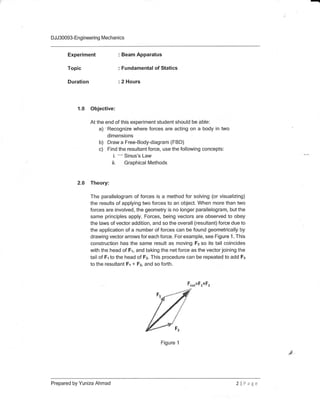
- 1. - DJJ30093-Engineering Mechanics Experiment : Beam Apparatus : Fundamental of Statics Topic Duration : 2 Hours 1.0 Objective At the end of this experiment student should be able: a) 'Recognize where forces are acting on a body in two dimensions b) Draw a Free-Body-diagram (FBD) c) Find the resultant force, use the following concepts: i. -- Sinus's Law ii. Graphical Methods 2.0 Theory: The parallelogram of forces is a method for solving (or visualizing) the results of applying two forces to an object. When more than two forces are involved, the geometry is no longer parallelogram, but the same principles apply. Forces, being vectors are observed to obey the laws of vector addition, and so the overall (resultant) force due to the application of a number of forces can be found geometrically by drawing vector arrows for each force. For example, see Figure 1 . This construction has the same result as moving F2 so its tail coincides with the head of Fr, and taking the net force as the vector joining the tail of Fr to the head of Fz. This procedure can be repeated to add Fa to the resultant F1 + Fz, and so forth. F,o.=f .+f, Fr Prepared by Yuniza Ahmad Figure 1 2lPage
- 2. - DJJ30093-Engineering Mechanics The law of sinus is useful for computing the lengths of the unknown sides in a triangle if two angles and one side are known. This is a common situation occurring in triangulation, a technique to determine unknown distances by measuring two angles and an accessible enclosed distance. Sin a Sin b Sin c Figure 2 3.0 Apparatus: B C 8. A C a) b) c) d) e) 4.0 Procedure: Beam Apparatus 5N and 10N weight slot Strings - 1.3m Protractor Meter Rule a) Assemble the apparatus as shown in Figure 3. b) Tie a 5N weight slot to middle of a 1.3m string. c) Use a protractor to measure the angles between the horizontal axis and string. Record < AC and < BC in Table 1. d) Using a suitable scale, draw a vector diagram to show the forces in action (Graphical methods) e) Repeat all the steps by using 10N weight. f) Write down your own conclusion from the results of this experiment. Prepared by Yuniza Ahmad 3lPage .;1
- 3. - DJJ30093-Engineeri ng Mechanics 5N r { String Weight slot Beam apparatus Figure 3 5.0 Data Collection Write the outcome of your observation from this experiment. Table 1 Data of Analysis: Table 2 Attachment Graph paper Calculation using Sinus's Law i) ii) G,6t / g-r 051/ f 5N G,b/rrf 6'b /10' 10N l 5N 10N Prepared by Yuniza Ahmad 4lPage LOAD
- 4. - DJJ30093-Engineering Mechanics Experiment : Beam Apparatus Topic : Force in Equilibrium Duration : 2 Hours 1.0 Objective: At the end of this experiment student should be able: a) To illustrate the conceptspf forces and their components b) Draw a Free-Body-diagram (FBD) c) Use data taken to prove an equilibrium of force 2.0 Theory: A particle is said to be in equilibrium if the particle is at rest (if originally at rest) or has a constant velocity (if originally in motion). However, the term'equilibriu m' or more precisely'static equilibrium' is normally used to describe an object at rest. ln order to maintain equilibrium, it is necessary to satisfy Newton's First Law of Motion. Newton's First Law of Motion requires that the resultant force acting on a pafticle to be equal to zero. This condition may be expressed AS IF=0. Where EF is the vector sum of all the forces acting on a pafticle. And the supporting forces also can be determined via balances of moments. Balance of moments around support A and B: IMA=0 RB(L)-FCX=0 RB=FC)(L FC RA R3 L Prepared by Yuniza Ahmad Figure 1 5lPage
- 5. - DJJ30093-Engi neering [Vlechanics 3.0 Apparatus: 4.0 Procedure: a) Beam Apparatus b) 10 N weight slot c) Steel bar a) Assemble the apparatus as shown in Figure 2. b) Tie a 10N weight slot to distance X from A. c) Take a value of force that EUpport using dynamometer Figure 2 I Prepared by Yuniza Ahmad SlPage f ,: L*ad F ! {t p ax
- 6. - DJJ30093-En gi neeri n g [4echanics Experiment Topic Duration : Simple Pendulum : Velocity and Acceleration : 2 Hours 1.0 Objective At the end of this experiment student should be able: a) Jo plot a T2- L graph using a simple pendulum. b) To find the effective length of the simple pendulum for a given time period using the graph. c) To calculate the acceleration due to gravity at a place. 2.0 Theory: An ideal simple pendulum consists of a heavy point mass (called bob) tied to one end of a per-fectly inextensible, flexible and weightless string. ln practice, we make it by tying a metallic spherical bob to a fine cotton stitching thread. Length of a Simple Pendulum The distance between the point of suspension of the pendulum and its Centre of Gravity (C.G.), which is the C.G. of the bob, is called the lengthof the simple pendulum. lt is represented using the alphabet ( L ). Time Period of a Simple Pendulum Time period is the time taken by the bob of the simple pendulum to make one complete oscillation. lt is represented by the letter T. Prepared by Yuniza Ahmad Bllrlr
- 7. - DJJ30093-Engineering Mechanics 5.0 Data Collection Write the outcome of your observation from this experiment. Table 1 Data of Analysis Table 2 Attachment i) Calculation loa ' L"rrt Ab 6o -lo s0 5 6 i, lo 10 cm il ln I 20 cm 3:0-cm f 2 Z 40 cm aI 4 0.1 0.2 0.3 0.4 Prepared by Yuniza Ahmad TlPage Data from Experiment Data from Theory RB (N)
- 8. - DJ J 30093- En g i neeri n g lVlecha ni cs Finding the acceleration due to gravity The time period of a simple pendulum depends on the length of the pendulum (l) and the acceleration due to gravity (g), which is expressed by the relation, L T*3 For small amplitude of oscillations, __t l r : rln'- ':*=[#J ,tt] u L i]1 . ie; u*4ml t- lf we know the value of L and T, we can calculate the acceleration due to gravity, g. The T2 against L graph We can plot a graph between T2 and L by taking T2 along the Y axis and L along the X axis. The graph is a straight line. t" From the graph, L AE. I ** i I FJ Prepared by Yuniza Ahmad 9lPage 1:
- 9. - DJJ30093-Engineering Mechanics 3.0 Apparatus 4.0 Procedure a) Piece of string b) Pendulum bob c) Pair of small flat pieces of wood or cork d) Reton stand with a clamp e) Stop watch 0 Meter rule g) Protractor h) Opticalpin i) Pair of scissors a) S&-up a simple pendulum as in Figure 1 Figure 1 b) Measure the length, / of the pendulum c) Swing the pendulum at less than 10o from the vertical in one plane and measure the time for 10 oscillations. Repeat the operation and calculate the average value. Then, determine the period of oscillation, Iof the pendulum. d) Repeat step (c) at least 3 times with different values of length, / of the pendulum. Record the values for / and f in Table 1. -r*r r/i: It Lt .li 't*iifi ,$,1*p wsteln Prepared by Yuniza Ahmad l0 llage Splil r*rk *{10* A E*t:
- 10. - DJJ30093-Engineering Mechanics 5.0 Data Gollection Data of Analysis Attachment i) Graph paper ii) Calculation Table 1 ,r,,q tq ,1u t-Gu 50 60 t6.sl la"q 16 .)o lL.q, t6 ,€o l(,,+e ll .f6 ll.+n 80 n ,66 t&.73 tk-7e 90 ts.g3 Prepared by Yuniza Ahmad 11 lPage 10 .lll.l.llllll,l:liltdSglh,l:,l,,..':tiillt: l,i iii ilil.i:ii:uutu,lltlttttQl lill,l:}',1:t:,,.; iil.:i)tlt:-i::iiiil:rrtltr::,rt:::airtliiiiriilllllrlit]1ii:iiilliiiriiia,::ir Ddta,,,_f iQm,,,Era,p.h.,.. Gravity, g (m/s2) 0.5 0.6 0.7 0.8 0.9
- 11. .- DJJ30093-Engi neering Mechanics Experiment Topic Duration : lncline Plane : Force and Motion : 2 Hours 1.0 Objective: At the end of this experiment student should be able To determine the coefficients of: a) static friction b) kinetic friction 2.0 Theory: Static friction mq Figure 1 Referring to Figure '1 , if force, P is increased; frictional force, F, also increase accordingly and the object will remain at rest. However, for a certain value of P, the object stafts to move. At this stage, the frictional force is known asthe limiting static frictional force, fs which are the maximum value of P. Kinetic friction lf the object is in motion, the frictional force is known as kinetic friction, fi.. The kinetic frictional force is less than the static frictional force. That explains why it is difficult to move an object which is initially at rest, but once it is in motion, less force is needed to maintain the motion. I : p.'o Prepared by Yuniza Ahmad rt F,K R 12 lPage Fr r
- 12. - DJJ30093-Engineering Mechanics Material Types and Coefficients 3.0 Apparatus a) lnclined plane b) A steel block c) Slotted mass with hooks d) String 4.0 Procedure a) Set up the apparatus as in Figure 2. Make sure that the string from the block is tied up horizontally to the pulley. Copper u = 0.20 Aluminium p =0.25 u =0.15 Steel u =0.30 Plastic (Polypropylene) Prepared by Yuniza Ahmad Figure 2 13 lPage
- 13. DJJ30093-Engineering lVlechanics b) Add the slotted weight onto the hook gradually until the block begins to slip. Record the total weight, [4/rin table 1. Repeat 3 times to get the average value of Wl c) Add different weight, Wo onto the block and repeat step (b). d) Repeat step (c) for at least 3 different values of Wu. e) Repeat step (b) but exert a little push to the block every time each mass added. Record the mass, 1,4/rin table 2 when the block moves slowly and steadily along the inclined plane. 0 Add different weight, Wa onto the block and repeat step (e) S) Repeat step (f) for at least 3 different values of Wo. 5.0 Data Collection Block of steel weight, Wu = 10 N Table 1: Total weight for Static Friction Table 2: Total weight for Kinetic Friction k5 0 .5 4,5 t, tr- b'J e"s 65 5 1.5 15 10 1.5 Prepared by Yuniza Ahmad 14 lP:;r wd (N) Wr (N) 2 3 Average Average 1 0 5 10
- 14. - DJJ30093-Engineering Mechanics a) Plot a graph of f"against R where fs= Wrand R = Wa+ Wn. Determine p", the coefficient of static friction from the graph b) Plot a graph of fLagainst R where fs= Wrand R = Wa+ Wo. Determine fl,, the coefficient of static friction from the graph Data of Analysis Attachment i. Graph paper ii. Calculation '10 15 20 Prepared by Yuniza Ahmad 15 lFage Static friction, ps Kinetic friction, ;.tr ,,Daielfiom,l t...::::t t' : .gf eih.,,: :,:,,,. Data from graph