
Recommended
More Related Content
What's hot
What's hot (20)
Viewers also liked
Viewers also liked (20)
Similar to Venturi Wet Dust Collector: High-Velocity Water Atomization for Efficient Particle Capture
Similar to Venturi Wet Dust Collector: High-Velocity Water Atomization for Efficient Particle Capture (20)
Venturi Wet Dust Collector: High-Velocity Water Atomization for Efficient Particle Capture
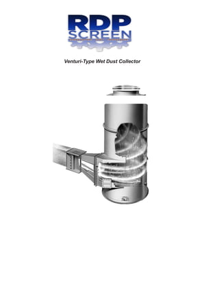
- 1. Venturi-Type Wet Dust Collector
- 2. Venturi-Type Wet Dust Collector Operating Principle The venture scrubber utilises kinetic energy to accomplish dust collection through the principle of impaction. The contaminated air stream is accelerated through a venturi shaped throat section reaching velocities between 9,000 and 24,000 feet per minute (100 to 280 miles per hour). Water introduced ahead of the throat is atomized by the high velocity air stream, and dust particles collide with and are captured in the millions of small droplets. In the long diverging section behind the throat, static pressure is regained as the velocity of the air stream is reduced. Sub-micron size particulate and water droplets coalesce during this interval providing additional collection. The water laden air stream enters the separator tangentially where droplets are removed by centrifugal force and impingement. Clean, droplet-free air passes through the separator outlet and slurry is continuously drained from the water eliminator section. Why the Venturi Shape? Wet scrubbers have been widely used for many years and depend on the mechanisms of inertial impaction, direct interception, and coalescence to collect dust or fume. They employ kinetic energy of the air stream to create the conditions required for air cleaning as follows: 1. Pressure, potential energy, is produced in the air stream by an air mover such as a centrifugal exhauster. 2. The potential energy is used to force the air stream through a constriction or orifice. This is the conversion of potential energy (static pressure) into kinetic energy (velocity). 3. Water is introduced at or ahead of the orifice by various methods and the high air velocity fragments or atomizes the water into millions of tiny droplets. 4. Since the water droplets have a low velocity relative to dust or fume particulate which has the same high velocity as the air stream, these particles collide with and are captured in the water droplets. orifice but less efficient conversion than the venturi. Due to its higher performance capabilities, the venturi-type collector has been categorized in its own classification rather than grouped with the orifice type. The venturi shape, provides the highest possible collection efficiency for a given power consumption, since the power expended is most effectively utilized. Sharp Edge Orifice vs. Venturi The venturi shape provides the most efficient conversion of potential energy (static pressure) into kinetic energy (velocity), and then allows maximum regain or reconversion of this high velocity back to static pressure as velocity diminishes in the diverging section. Many orifice-type collectors utilize a construction shape somewhere between that of the sharp edged orifice and the venturi, and demonstrate a more efficient energy conversion than the sharp edged A. Sharp edged orifice shown in cross section with air passing through it. The air stream obtains a cross section which is smaller than the orifice and is referred to as the “Vena Contracta.” Here, maximum velocity occurs. High shock losses are encountered as the air converges abruptly to enter the orifice. B. Venturi cross section (using venturi shape) shown with air passing through it. The venturi cross section follows the contour of the stream lines and the “Vena Contracta” occurs in throat area Angle diverging section allows maximum reconversion of velocity pressure to static pressure. Shock losses are minimized with shaped inlet.
- 3. Unique Water Injection System and Water Requirements A new concept for injection of water is used. The water is injected in the form of sheets rather than solid jets or sprays. This sheet is introduced forcefully, under pressure, to achieve optimum trajectory and complete throat coverage. There are no void areas through which the contaminated air can bypass. Water requirements for the venturi from 6 to 12 gal/1000 cu. ft. of air. Water can be recirculated if sufficient make-up to replace evaporation losses is added. The recirculating system must contain some means of clarification or at least be designed to limit the concentration of suspended solids. Normal pressure requirement is 40 psig at the supply manifold. Where recirculated water is anticipated to be quite dirty, larger jets with lower pressure requirements may be provided. Injection system for the venturi. Manual reamers are an optional accessory. The relatively large diameter of the jets and the use of reamers allow recirculation of water without concern for pluggage. View into the inlet, as the dirty incoming air would see it. This picture shows clearly the complete water coverage of the throat area. Typical “High Energy” Wet Collectors Damper Type Orifice/Baffle Type Sphere Type Annular Slot All of the above demonstrate high shock loss at the inlet as air converges without the benefit of a shaped entrance. Eddy currents exist within the air to water contact zone presenting voids and increased pressure loss. As a result of the abrupt enlargement of the air stream, extreme turbulence occurs behind the water contact region, thus eliminating the possibility of regain. The venturi shape of combines efficient conversion of pressure into velocity with maximum regain and complete coverage of the collection zone with low velocity water droplets. High energy consumption does not necessarily mean effective utilization and a comparable collection efficiency.
- 4. The v has been designed to provide the high degree of collection efficiency required for difficult air pollution problems. Considered to be one of the most sophisticated of wet collectors from a performance standpoint, it is still operationally simple, rugged, and dependable. • Deflector plates are provided ahead of the throat section which are easily replaceable. • Manual reamers can be provided for insurance against jet pluggage due to solids in recirculated water. • Other than the reamers there are no moving parts in the standard venture. A variable throat design is available if operating conditions should indicate the need for such an arrangement. • The vemturi has been fabricated of mild steel. selection of the proper materials if corrosive agents are present. The venturi is the heart of the collection system; but since its purpose is only to collect dust within the water droplets, it must be followed by an entrainment eliminator or separator. Air Flow Water Supply Connection Water Supply Manifold Deflector Plate (Removable) Complete Throat Coverage in Zone where air velocity is maximum Outlet to Water Eliminator
- 5. Cyclonic Separator The Separator uses the principle of cyclonic action to separate the dust laden water droplets from the air stream. The air enters the lower portion of the separator tangentially. Centrifugal force is employed to capture the water droplets on the sides of the separator’s cylindrical housing and the captured water droplets are eliminated through a drain in the bottom of the separator. The clean dry air stream is discharged out of the top portion of the Cyclonic Separator by either a side or a top outlet. The Cyclonic Separator offers maintenance free operation because of its simplicity of operation. There are no moving parts or small air passages to plug. An access door is provided on the air inlet for easy entry into the separator’s interior. Typical Arrangement with Cyclonic Separator Air from Process Cyclonic Separator Supply Water Slurry to Disposal Reclamation, or Clarification Exhauster Stack