SlideShare a Scribd company logo
1 of 15
Download to read offline
Proactive and Predictive Strategies For Setting Oil Analysis Alarms
And Limits
In the past, users of oil analysis have relied almost exclusively on the commercial laboratory to set
and enunciate data alarms. This has put an unrealistic burden on the labs to understand
information about user-equipment they have never seen. Likewise, the goals and objectives of the
user with respect to reliability and maintenance may not be fully understood. Usually, this leaves
the lab with no alternative other than to use standard default alarms. When these one-size-fits-all
alarms are used, many of the opportunities and objectives of a modern condition-based
maintenance program are missed.
In recent years, with the advent of sophisticated user-level oil analysis software, many site oil
analysis technologists are taking responsibility for setting alarms and limits independent of the lab.
The lab, in turn, is being asked to only deliver accurate and timely oil analysis results, leaving
interpretation and exception reporting to the user. With the user being familiar with the lubricants,
machines, historical problems, and general reliability goals, the most proper and effective limits can
then be set. However, a critical ingredient is a sufficient level of training in oil analysis by the user.
What are Oil Analysis Alarms and Limits?
When plant-level oil analysis software is employed, one of the main benefits is the funneling down
(or filtering) of the amount of data actually viewed and analyzed. This data reduction goal is
essential and relates to the tactical goal of exception reporting, that is, the viewing of only the data
that is out of compliance with acceptable trends or levels. All other data is held and managed in a
database for future reference and use. The limits, when properly set, give confidence that
conforming fluids are, in fact, okay and that non-conforming conditions have been caught
proactively.
FIGURE 1 Illustration of Upper and Lower Oil Analysis Limits
Because the goals and expectations vary considerably from one organization to another these
limits are best set by those charged with the responsibility of machine reliability and long fluid life.
They are also influenced by machine and application specific considerations. For instance, where
the gear box loads and duty cycle are low in one application, they may exceed rated levels in
another. The availability of spares and standby equipment may influence the decision with equal
magnitude. And, the age of the machine or lubricant may impact the placement of limits in certain
cases.
Basically, a limit or alarm is a strategically placed "trip wire" that alerts you to an abnormal
condition. Some data parameters have only upper limits such as particle counts or wear debris
levels. A few data parameters apply a few lower limits like TBN, additive elements, flash point, and
FTIR (additive). Other data parameters use both upper and lower limits. These might relate to
important chemical and physical properties of the lubricant such its viscosity (see Figure 1). The
computer trends the data and normally no alarm is reported as long as the limits are not exceeded.
When an exception exists the software is designed to alert and direct corrective action in response
to the deleterious result. To insure maximum benefit from oil analysis, careful thought needs to go
into the type of limit used and its setting.
Some Limits are More Proactive
Proactive limits are designed to alert users to abnormal machine conditions associated with root
causes of machine and lubricant degradation. They are keyed to the proactive maintenance
philosophy of setting targets (or standards) and managing the lubricant conditions to within the
targets. A strategic premise is that these conditions are controlled to levels that are improvements
over past levels and that these become goals. Best results occur when progress towards achieving
these goals are charted conspicuously by the maintenance organization. These types of limits are
referred to as "goal-based," see Figure 2.
FIGURE 2 Goal-Based Limits Are Set For Certain Data Parameters To Proactively Improve
Machine And Lubricant Reliability
In order to set a goal-based limit a level of machine reliability is identified. Again, this needs to be
an improvement over previous levels. If, for instance, we use particle count as the parameter then
we need to select a "target cleanliness" which is a marked improvement from before. The target
cleanliness becomes the limit. In the example, if previously contaminant levels were averaging
about ISO 18/15 for a hydraulic system, a limit set at 15/12 would be a goal-based improvement. A
life extension of three times (MTBF) would be expected based on controlled field studies. If, on the
other hand, we set a limit of 18/15 our effort is downgraded to the detection of major faults only.
Goal-based limits of this type can be applied to particle counts, moisture levels, glycol levels, fuel
dilution, TAN, and other common failure root cause conditions.
Another similar type of proactive limit relates to the progressive aging of the lubricant or hydraulic
fluid. From the moment the oil is first put into service its physical and chemical properties transition
away from the ideal (i.e., those of the new formulated oil). For some properties the transition may
be extremely slow but for others it can be abrupt and dynamic. Limits keyed to the symptoms of
lubricant deterioration are referred to as "aging limits," see Figure 3. They are designed to signal
the need for a well-timed condition-based oil change and are usually pegged to the depletion of
additives and the thermal/oxidative degradation of the base oil.
FIGURE 3 :Aging-Limits Are Keyed To Degrading Additive Base-Stock Properties
In order to properly set aging limits the new lubricant must be analyzed to reveal its physical and
chemical properties. This will become the oil's "base signature." Care must be taken to insure that
the new oil is analyzed using the same test procedures and instruments that will be used to
analyze the used oil. Under no circumstances should these "base signature" properties be simply
lifted off the lubricant's spec sheet as provided by the supplier. Instruments and test methods vary
substantially and new oils are approved if their properties fall within a tolerance range.
For instance, ISO viscosity grades vary plus/minus ten percent from a nominal center point (grade).
This means that a VG 68 lubricant would be "in grade" from 61 to 75 centistokes (cSt). This is too
much variance for 68 centistokes to serve as a proper baseline. However, if the actual viscosity of
a specific lubricant was measured and found to be 64 cSt then a precise baseline is now available
against which the used oil can be trended. Aging limits can be effectively applied to such
parameters as TAN, TBN, viscosity, RBOT, emission spectroscopy for additive elements, FTIR (for
oxidation, nitration, & sulphation), and dielectric constant.
Aging limits often follow trendable data patterns, i.e., they trend steadily in the direction of the limit.
The actual time to limit might be predicted by linear or non-linear regression; a feature in some oil
analysis software products. For instance, the following equation might be applied to estimate the
remaining useful life of a turbine oil using Rotating Bomb Oxidation Test (RBOT):
Lower aging limits are generally set for additive depletion, RBOT life, and TBN. Upper limits are set
for dielectric constant, TAN, and FTIR for oxidation, sulphation, and nitration trends. And both
upper and lower limits should be set for viscosity. The table in Figure 4 shows some example limits
for both goal-based and aging parameters.
FIGURE 4 Example of Goal-Based Limits
Other Limits are More Predictive
Predictive limits are set to signal the presence of machine faults or abnormal wear conditions.
They are aligned with the goals of predictive maintenance, i.e., the early detection of machine
failure symptoms as opposed to failure root causes (proactive maintenance). In oil analysis, a
proper predictive limit set to the correct parameter has many advantages over other predictive
maintenance technologies. Specifically, it offers reliable incipient fault detection, spanning a wide
range of machine failure modes. It is seer-like in that it has the ability to forecast a future event. As
compared to vibration analysis for instance, the time-based detection window using ferrous density
analysis has been demonstrated to exceed 15 times for common gear boxes failures.
Rate-of-change limits are generally identified as predictive. These are set to a property that is
being progressively introduced to the oil, such as wear debris. The add rate (change) might be
calculated per unit time, for instance ppm iron per 100 hours on oil. When the parameter's value is
plotting against time the rate-of-change (add rate) equates to the current slope of the curve. As an
alternative to representing rate-of-change, slope can be quantified by dividing rise by run for a fixed
period of time (see Figure 5). The linear trends also points to the approximate time interval
remaining before a level-type limit is exceeded. Unlike level limits however, rate-of-change limits
ignore the absolute value of a data parameter, emphasizing instead the speed (rate) at which the
level is changing.
This can be best illustrated by an example. Suppose for a given machine, such as an industrial
gear unit, iron is typically introduced to the oil at roughly 5 ppm per month. The first month after an
oil change the iron shows 5 ppm, the expected level. After the second month the iron shows 10
ppm, again this is expected (5 + 5). The same holds for the end of the third month when 15 ppm is
reported. The add rate of 5 ppm per month remains uninterrupted. However, by the end of the
fourth month the unexpected result of 50 ppm is obtained. The computer software shows this as a
critical. The reason is not due to the fact that 50 ppm in a gear lube signals abnormal wear. In fact
this is a rather common iron concentration in gear oils. However, the alarm is responding to the
rate at which the iron concentration changed in the last month of service (35 ppm instead of the
expected 5 ppm). Had rate-of-change limits not been applied this exception might not have been
reported.
FIGURE 5 Using Rate-of-Change Limits (rise/run) Must Be Calculated For The Trending Data
Parameter
The use of rate-of-change limits is well suited for wear debris analysis but can be used for other
parameters as well. Examples of where it is commonly applied include particle counts, elemental
wear metals, ferrous density analysis (DR, PQ 90, Wear Particle Analyzer, ferrous Contam-Alert),
TAN, and RBOT. It should be noted that multiple limit strategies can be used for single test
parameters, i.e., where rate-of-change limits are applied so too are level limits (aging, proactive,
and statistical).
Statistical Limits are Predictive as Well
For many years statistical limits have been used successfully in oil analysis. The practice requires
the availability of a certain amount of historical data on the target parameters (see Figure 6). A
population standard deviation is calculated. Upper limits are then set relating to the number of
standard deviations (sigmas) above the sample population average. Many analysts put a caution at
one or two sigmas and a critical at two or three sigmas. When one sigma is exceeded this means
that the value from the test result exceeds 68 percent of historical samples. A result that alarms at
two sigmas exceeds 95 percent of historical data. Three sigma exceedance corresponds to of 99.7
percent of the database.
Many commercial laboratories have large repositories of data spanning numerous machine types
and models. These data permit the relatively easy calculation of national averages and
corresponding population standard deviations (sigmas). In some cases the data can be
conveniently sorted according to industry and application. These same databases can be used to
assist in the setting of rate-of-change limits as well. Typical applications of statistical limits include
elemental analysis of wear metals, ferrous density analysis (DR, PQ 90, etc.), and other common
predictive oil analysis measures.
It is well known that many machines exhibit highly individual characteristics. They might trend high
or low when compared to national averages. Data from a machine that is a low reader might not
alarm early enough when national averages are used as the statistical base (false negative).
Likewise, when a high reader is encountered (potential false positive), it may be well advised to
adjust the statistical limit accordingly, or simply rely more heavily on rate-of-change limits.
FIGURE 6 Statistical Limits Are Keyed To Historical Oil Analysis Trends
Dealing With Data Noise
Data noise can mask or distort the target data parameter (and trend) often making it nearly invisible
to detection. And, when data noise exists it can inhibit the ideal placement of certain alarms and
limits. A machine that normally has a high level of wear particles in its lubricating oil is a good
example. These particles do not represent current wear activity but are an accumulation of
historical wear, possibly going back many months. This is a common situation when course filters
or no filters are in use. This high concentration of wear particles constitutes noise for an oil analysis
program.
FIGURE 7 Clean Fluids Help Provide Improved Fault Detection Sensitivity
While the target signal (data) is current wear levels, these particles may be extremely difficult if not
impossible to measure when they are mixed indiscriminately with historical wear debris. This
equates to low signal-to-noise ratio. Crudely stated the fault signal is getting lost in the sauce. This
situation is illustrated in Figure 7. When particle concentrations are controlled to an ISO 19/16 fault
detection is poor. By comparison, the ISO 13/10 fluid translates to high-resolution detection, i.e.,
high signal-to-noise ratio. A similar problem occurs with infrared spectroscopy when weak
absorption signals are lost due to inaccurate reference spectra and the presence of interfering
materials in oil.
Summary
With the current trend of users taking control of the their oil analysis programs there has been a
surge of interest in education. This has recently lead to an STLE (Society of Tribologist and
Lubrication Engineers) committee being formed to offer oil analysis certification levels. While oil
analysis education is often aimed at data interpretation it is no less important in the area of limit
setting. In fact, limit setting and data interpretation are co-mingled activities. When oil analysis
limits are properly set and the correct tests are performed at the right frequency, data interpretation
is easy and efficient.
The strategic use of goal-based and aging limits enables proactive maintenance to be carried out
at the highest level. Likewise, when rate-of-change and statistical limits are deployed, the benefits
of early fault detection are achieved. The combination of these limit-setting strategies affords the
broadest and most effective protection for the plant equipment and its lubrication assets.
Clean Oil Sampling
How to Sample Oil Without Opening the Bottle
Proper oil sampling does not have to be a difficult or unpleasant experience. In fact, when the best
sampling methods (and hardware) are employed the experience should be just the opposite. There
are many important lessons to learn when it comes to pulling a sample. Many run contrary to
intuition. Most of them have to do with insuring that what enters the bottle is both rich in information
and remains undisturbed by the sampling process itself. It is this later concern that is addressed by
this article.
Modern oil analysis programs typically include some tests that can be influenced by environmental
contaminants entering the oil (bottle) during the sampling process. Tests of greatest risk include
particle counting, elemental spectroscopy, and total acid number. In situations where there is
considerable dust in the environment at the time the sample is pulled, a concerted effort needs to
be made to insure that this dust does not contaminate the oil. Examples of high-risk
situations/environments include mine sites, construction sites, primary metals industries, foundries,
windy outdoor conditions, and sample points close to the ground.
Experiments on the influence of environmental dust on particle counts have shown a marked
effect. It is not unusual for an oil’s ISO code to increase 2-3 range numbers when a bottle is left
open just a few minutes. For instance, the actual oil sampled might be a rather clean ISO 13/10 but
after exposing the sample bottle to atmosphere it can show an ISO 16/13. The amount of dirt
needed to accomplish an ISO 16/13 is only about 1 ppm.
Recently, a new method called “clean oil sampling” has emerged that greatly simplifies the process
and minimizes the risk of dirt entering the bottle. It involves the use of common zip-lock sandwich
bags and sampling hardware such as vacuum pumps and probe devices. Below is an outline
description of this procedure:
Step One
Obtaining a good oil sample begins with a bottle of the correct size and cleanliness. The topic of
bottle cleanliness will be discussed in greater detail in a future issue of Practicing Oil Analysis.
However, it is understandable that the bottle must be at a known level of cleanliness and that this
level should be sufficiently high so as not to interfere with expected particle counts.
Some people relate this to a signal-to-noise ratio, i.e., the target cleanliness level of the oil (signal)
should be several times the expected particle contamination of the bottle (noise). For more
information on bottle cleanliness refer to ISO 3722.
StepTwo
Before going out into the plant with the sample bottles place the capped bottles
into very thin zip-lock sandwich bags; one per bag. Zip each of the bags such that air is sealed into
the bag along with the bottles. This should be done in a clean-air indoor environment in order to
avoid the risk of particles entering the bags along with the bottles. After all of the bottles have been
bagged, put these small bags (with the bottles) into a large zip-lock bag for transporting them to the
plant or field. Sampling hardware such as vacuum pumps and probe devices should be placed in
the large bag as well.
Step Three
After the sampling port or valve has been properly flushed (including the sampling pump or probe if
used) remove one of the bags holding a single sample bottle. Without opening the bag, twist the
bottle cap off and let the cap fall to the side within the bag. Then move the mouth of the bottle so
that it is away from the zip-lock seal. Do not unzip the bag.
Step Four
Thread the bottle into the cavity of the sampling device (vacuum pump or probe). The plastic tube
will puncture the bag during this process, however, try to avoid other tears or damage to the bag
(turn the bottle, not the probe or pump, while tightening). If a probe device is used, it is advisable to
break a small hole in the bag below the vent hole with a pocket knife. This permits air to escape
during sampling.
Step Five
The sample is then obtained in the usual fashion until the correct quantity of oil has entered the
bottle. Next, by gripping the bottle, unscrew it from the cavity of the pump or probe device. With the
bottle free and still in the bag, fish the cap from the bottom of the bag onto the mouth of the bottle
and tighten.
Step Six
With the bottle capped it is safe to unzip the bag and remove the bottle. Confirm that the bottle is
capped tightly. The bottle label should be attached and the bottle placed in the appropriate
container for transport to the lab. Do not reuse the zip-lock bags.
Benefits of Clean Oil Sampling
This simple procedure effectively permits samples to be obtained without exposing the fluid or the
bottle to the atmosphere or surface contamination. A clean sample can even be obtained with dirty
hands. There are no expensive materials to purchase and the technique can be applied to a large
number of sampling situations. For best results practice a few times with a spare bottle until the
technique is perfected.
What Particles Mean and Why They Need to
be Monitored and Controlled
With the widespread use of plant-level particle counters, maintenance organizations are
increasingly more sophisticated and skilled in the management and control of oil
cleanliness. This has led to the discovery of a host of new tactics and practices in
combining the particle counter with other important onsite oil analysis tools and methods;
many unheard of just a few years ago.
Contamination can be defined as any unwanted substance or
energy that enters or contacts the oil. Contaminants can come in a
great many forms, some are highly destructive to the oil, its
additives, and machine surfaces. It is often overlooked as a source
of failure because its impact is usually slow and imperceptible yet,
given time, the damage is analogous to eating the machine up from
the inside out. While it is not practical to attempt to totally eradicate
contamination from in-service lubricants, control of contaminant levels within acceptable limits is
accomplishable and vitally important.
Particles, moisture, soot, heat, air, glycol, fuel, detergents, and process fluids are all contaminants
commonly found in industrial lubricants and hydraulic fluids. However, it’s particle contamination
that is widely recognized as the most destructive to the oil and machine. This explains why the
particle counter is the most widely used instrument in oil analysis today. And, the central strategy to
its success in reducing maintenance costs and increasing machine reliability is proactive
maintenance.
Proactive Maintenance. While the benefits of detecting abnormal machine wear or an aging
lubricant condition are important and frequently achieved with oil analysis programs, they should
be regarded as low on the scale of importance compared to the more rewarding objective of failure
avoidance. This is achieved by treating the causes of failure, not simply the symptoms. And,is is
the foundation of the popular practice known as proactive maintenance. In fact, the only effective
way to obtain simple solutions to complex machine maintenance problems is through proactive
maintenance.
Whenever a proactive maintenance strategy is applied, three steps are necessary to insure that its
benefits are achieved. Since proactive maintenance, by definition, involves continuous monitoring
and controlling of machine failure root causes, the first step is simply to set a target, or standard,
associated with each root cause. In oil analysis, root causes of greatest importance relate to fluid
contamination (particles, moisture, heat, coolant, etc.).
However, the process of defining precise and challenging targets (e.g., high cleanliness) is only the
first step. Control of the fluid's conditions within these targets must then be achieved and
sustained. This is the second step and often includes an audit of how fluids become contaminated
and then systematically eliminating these entry points. Often better filtration and the use of
separators are required.
The third step is the vital action element of providing the feedback loop of an oil analysis program.
When exceptions occur (e.g., over target results) remedial actions can then be immediately
commissioned. Using the proactive maintenance strategy, contamination control becomes a
disciplined activity of monitoring and controlling high fluid cleanliness, not a crude activity of
trending dirt levels.
Finally, when the life extension benefits of proactive maintenance are flanked by the early warning
benefits of predictive maintenance, a comprehensive condition-based maintenance program
results. While proactive maintenance stresses root-cause control, predictive maintenance targets
the detection of incipient failure of both the fluid's properties and machine components like
bearings and gears. It is this unique, early detection of machine faults and abnormal wear that is
frequently referred to as the exclusive domain of oil analysis in the maintenance field.
Managing Particle Contamination. There is no single property of lubricating oil that challenges
the reliability of machinery more than suspended particles. It would not be an exaggeration to refer
to them as a microscopic wrecking crew. Small particles can ride in oil almost indefinitely and
because they are not as friable (easily crumbled) as their larger brothers, the destruction can be
continuous. Many studies have shown, with convincing evidence, the greater damage associated
with small particles. Still, most maintenance professionals have misconceptions about the size of
particles and the associated harm caused.
These misconceptions relate to the definition people apply to what is clean oil and what is dirty oil.
And, it is this definition that influences the setting of appropriate target cleanliness levels for
lubricating oils and hydraulic fluids. The process is not unlike a black box circuit. If we want a
change to the output (longer and more reliable machine life) then there must be a change to the
input (a lifestyle change, i.e., improved cleanliness). For instance, it’s not the monitoring of
cholesterol that saves us from heart decease, instead it's the things we do to lower the cholesterol.
Therefore the best target cleanliness level is one that is a marked improvement from historic levels.
While there are numerous different methods used to arrive at target cleanliness levels for oils in
different applications, most combine the importance of machine reliability with the general
contaminant sensitivity of the machine to set the target. The Reliability Penalty Factor and the
Contaminant Severity Factor are arrived at by a special scoring system that is included with the
Target Cleanliness Grid.
There are many expensive ways to achieve clean oil but experience has taught us the wisdom of
contaminant exclusion–treating the cause not just the symptom. By effectively excluding the entry
of contaminants and promptly removing contaminants when they do enter, the new cleanliness
targets are frequently achieved. Concerns that filtration costs will increase are not often realized
due to the greater overall control, especially from the standpoint of particle ingression.
Particle Counting—The "Invisible" Filter. Engineers learn that "controlled systems" are those
that have feedback loops. In proactive maintenance this is the monitoring step, i.e., particle
counting. If this is done on a frequent enough basis, not only is proactive maintenance achieved
but also a large assortment of common problems can be routinely detected. As such, particle
counting is an important "catch all" type test. Because of the obvious value, it is not uncommon to
find organizations testing the cleanliness of their oils as frequently as weekly.
The activity of routine particle counting has a surprising impact on achieving cleaner oils. When the
cleanliness of oil's are checked and verified on a frequent basis a phenomena known as the
"invisible filter" occurs, which is analogous to the saying, "what gets measured gets done."
Because a great deal of dirt and contamination that enters oils often come from the careless
practices of operators and craftsmen, the combined effect of monitoring with a modicum of training
can go a long way toward achieving cleanliness goals.
The following are common proactive and predictive maintenance uses of an onsite particle counter:
Proactive Maintenance:
1. Routinely verify that in-service oils are within targeted cleanliness levels.
2. Check the cleanliness of new oil deliveries.
3. Quickly identify failed or defective filters.
4. Confirm that seals and breathers are keeping contaminants out.
5. Confirm that systems are properly cleaned and flushed after repair.
6. Confirm that new machines are cleaned and flushed before use.
7. Identify the use of dirty top-up containers and poor maintenance practices.
8. Identify the timing for filter cart use.
Predictive Maintenance:
1. Identify early-stage abnormal machine wear with quick confirmation by repeating.
2. Identify the location/source of abnormal wear by multi-point isolating methods.
3. Verify the effectiveness of corrective maintenance and botched repair jobs.
4. Monitor machine break-in wear generation.
5. Identify abnormal rust and corrosion products in the oil.
6. Assist in confirming machines are balanced and aligned.
7. Permit more "on-condition" laboratory oil analysis.
8. Serve as an effective screen for wear debris analysis.
There are many different types of automatic particle counters used by oil analysis laboratories.
There are also a number of different portable particle counters on the market. The performance of
these instruments can vary considerably depending on the design and operating principle. Particle
counters employing laser or white light are widely used because of their ability to count particles
across a wide range of sizes. Pore-blockage type particle counters have a more narrow size range
sensitivity; however, they're also popular because of their ability to discriminate between hard
particles of other impurities in the oil. When good procedures and practices are followed, both
types of particle counters provide value and effectiveness in maintenance applications.
Figure 2 shows how particle count trends vary depending on the machine
application and the presence of an onboard filter. Because particle counters
monitor particles in the general size range controlled by filters, equilibrium is
usually achieved, i.e., particles entering the oil from ingression minus
particles exiting from filtration will leave behind a steady-state concentration.
When filters are properly specified and ingression is under control this
steady-state concentration will be well within the cleanliness target. Systems
with no continuous filtration, e.g., a splash-fed gearbox, the equilibrium is
not effectively established (there is no continuous particle removal). This
causes the particle concentration to be continuously rising. Still, contamination control can be
achieved by periodic use of portable filtration systems like a filter cart.
By combining the use of a particle counter with other onsite oil analysis tools, particle count trends
can be more effectively interpreted. Figure 3 shows how particle count trends from a circulating
industrial gearbox can be monitored and interpreted when ferrous density analysis is added as an
exception test.
Ferrous density analysis instruments are sold by several suppliers and include DR ferrograph,
Particle Quantifier, and Ferrous Particle Counter. Figure 4 shows how particle trends can be
compared to viscosity trends to reveal a host of crankcase lubrication problems.
Training—Key to Success. Like most activities in oil analysis and maintenance technology,
success in particle counting and contamination control requires education and skill development.
Unless maintenance professionals have an understanding of the purpose and goals of oil analysis
and are literate in the language of oil analysis, they cannot be expected to carry out its mission.
This is accomplished through a liberal amount of training and education. And, this should not
simply be concentrated on a single individual but should be spread about to all those that benefit
from and contribute to machine reliability. In fact, training and education should occur at several
different levels including craftsmen, operators, engineering, and management. Below are a few
subjects for which seminars and training classes are generally available:
Figure 2
Figure 3
Figure 4
1. Lubrication fundamentals and their use
2. Mechanical failure analysis
3. Proactive maintenance and root cause analysis
4. Troubleshooting hydraulic systems
5. Lubrication and maintenance of bearings and gear units
6. Oil analysis fundamentals
7. Oil analysis data interpretation
8. Filtration and contamination control
9. Wear particle analysis machine fault detection
Once these fundamentals are in place, oil analysis can move forward enthusiastically, beginning
with the development of its mission and goals. And, instead of indifference to oil analysis
exceptions, rapid-fire corrections are carried out and measures are taken to preempt their
reoccurrence. In time, unscheduled maintenance becomes rare and oil analysis exceptions are few
as the idealized machine operating environment becomes controlled.
Finally, as the many elements of oil analysis and proactive maintenance merge together into a
cohesive maintenance activity, the benefits should not be allowed to go unnoticed. Unlike many
applications of new technology, proactive maintenance seeks non-events as its goal and reward.
These non-events include oil that continues to be fit-for-service, machines that don't break down,
and inspections that don't need to be performed. This quiet existence is the product of a highly
disciplined activity but, at times, can be misunderstood by the casual observer as unneeded.
Therefore, the close association of the activities of proactive maintenance with the benefits of
proactive maintenance must be measured, monitored, and displayed for all to view.

More Related Content

Similar to oil-analysis-best-practices.pdf

01 Overview of Power transformers - Remedial Measures.ppt
01 Overview of Power transformers - Remedial Measures.ppt01 Overview of Power transformers - Remedial Measures.ppt
01 Overview of Power transformers - Remedial Measures.pptvikram desai
 
Maximo Oil and Gas 7.6.1 HSE: Change Module options
Maximo Oil and Gas 7.6.1 HSE: Change Module optionsMaximo Oil and Gas 7.6.1 HSE: Change Module options
Maximo Oil and Gas 7.6.1 HSE: Change Module optionsHelen Fisher
 
Representative Testing of Emissions and Fuel Consumption of Working Machines ...
Representative Testing of Emissions and Fuel Consumption of Working Machines ...Representative Testing of Emissions and Fuel Consumption of Working Machines ...
Representative Testing of Emissions and Fuel Consumption of Working Machines ...Reno Filla
 
Lubricated Air Compressors - Operating and Maintenance Procedures Required to...
Lubricated Air Compressors - Operating and Maintenance Procedures Required to...Lubricated Air Compressors - Operating and Maintenance Procedures Required to...
Lubricated Air Compressors - Operating and Maintenance Procedures Required to...Gerard B. Hawkins
 
Damage equivalent test methodologies journal bearings
Damage equivalent test methodologies   journal bearingsDamage equivalent test methodologies   journal bearings
Damage equivalent test methodologies journal bearingsThiruchitrambalam M
 
IRJET- Engine Oil Color Monitoring System
IRJET- Engine Oil Color Monitoring SystemIRJET- Engine Oil Color Monitoring System
IRJET- Engine Oil Color Monitoring SystemIRJET Journal
 
Diesel Lubricity Improver | Petroleum Logistics
Diesel Lubricity Improver | Petroleum LogisticsDiesel Lubricity Improver | Petroleum Logistics
Diesel Lubricity Improver | Petroleum LogisticsPetroleum Logistics
 
Tribology proper lubricant_selection Mr Tùng - 0987 988 407 | www.khodaumo.com
Tribology proper lubricant_selection Mr Tùng - 0987 988 407 | www.khodaumo.comTribology proper lubricant_selection Mr Tùng - 0987 988 407 | www.khodaumo.com
Tribology proper lubricant_selection Mr Tùng - 0987 988 407 | www.khodaumo.comĐỗ Bá Tùng
 
To study methodology and analysis of gearbox
To study methodology and analysis of gearboxTo study methodology and analysis of gearbox
To study methodology and analysis of gearboxRAJPUT ARVINDSINGH
 
How to use the GBHE Reactor Technology Guides
How to use the GBHE Reactor Technology GuidesHow to use the GBHE Reactor Technology Guides
How to use the GBHE Reactor Technology GuidesGerard B. Hawkins
 
The International Journal of Engineering and Science (IJES)
The International Journal of Engineering and Science (IJES)The International Journal of Engineering and Science (IJES)
The International Journal of Engineering and Science (IJES)theijes
 
Oil and gas reserves report under ps as in oil and gas industry
Oil and gas reserves report under ps as in oil and gas industryOil and gas reserves report under ps as in oil and gas industry
Oil and gas reserves report under ps as in oil and gas industryHamdy Rashed
 
XFT_Commercial_Introduction_White_Paper
XFT_Commercial_Introduction_White_PaperXFT_Commercial_Introduction_White_Paper
XFT_Commercial_Introduction_White_PaperGibson Mrewa
 
Optimization of Separator Train in Oil Industry
Optimization of Separator Train in Oil IndustryOptimization of Separator Train in Oil Industry
Optimization of Separator Train in Oil IndustryIRJET Journal
 
IRJET- Risks Prioritization using AHP Method -A Case Study
IRJET- Risks Prioritization using AHP Method -A Case StudyIRJET- Risks Prioritization using AHP Method -A Case Study
IRJET- Risks Prioritization using AHP Method -A Case StudyIRJET Journal
 

Similar to oil-analysis-best-practices.pdf (20)

01 Overview of Power transformers - Remedial Measures.ppt
01 Overview of Power transformers - Remedial Measures.ppt01 Overview of Power transformers - Remedial Measures.ppt
01 Overview of Power transformers - Remedial Measures.ppt
 
Maximo Oil and Gas 7.6.1 HSE: Change Module options
Maximo Oil and Gas 7.6.1 HSE: Change Module optionsMaximo Oil and Gas 7.6.1 HSE: Change Module options
Maximo Oil and Gas 7.6.1 HSE: Change Module options
 
Representative Testing of Emissions and Fuel Consumption of Working Machines ...
Representative Testing of Emissions and Fuel Consumption of Working Machines ...Representative Testing of Emissions and Fuel Consumption of Working Machines ...
Representative Testing of Emissions and Fuel Consumption of Working Machines ...
 
Lubricated Air Compressors - Operating and Maintenance Procedures Required to...
Lubricated Air Compressors - Operating and Maintenance Procedures Required to...Lubricated Air Compressors - Operating and Maintenance Procedures Required to...
Lubricated Air Compressors - Operating and Maintenance Procedures Required to...
 
Damage equivalent test methodologies journal bearings
Damage equivalent test methodologies   journal bearingsDamage equivalent test methodologies   journal bearings
Damage equivalent test methodologies journal bearings
 
IRJET- Engine Oil Color Monitoring System
IRJET- Engine Oil Color Monitoring SystemIRJET- Engine Oil Color Monitoring System
IRJET- Engine Oil Color Monitoring System
 
AlignOlefinOpsEPC
AlignOlefinOpsEPCAlignOlefinOpsEPC
AlignOlefinOpsEPC
 
Diesel Lubricity Improver | Petroleum Logistics
Diesel Lubricity Improver | Petroleum LogisticsDiesel Lubricity Improver | Petroleum Logistics
Diesel Lubricity Improver | Petroleum Logistics
 
Tribology proper lubricant_selection Mr Tùng - 0987 988 407 | www.khodaumo.com
Tribology proper lubricant_selection Mr Tùng - 0987 988 407 | www.khodaumo.comTribology proper lubricant_selection Mr Tùng - 0987 988 407 | www.khodaumo.com
Tribology proper lubricant_selection Mr Tùng - 0987 988 407 | www.khodaumo.com
 
To study methodology and analysis of gearbox
To study methodology and analysis of gearboxTo study methodology and analysis of gearbox
To study methodology and analysis of gearbox
 
How to use the GBHE Reactor Technology Guides
How to use the GBHE Reactor Technology GuidesHow to use the GBHE Reactor Technology Guides
How to use the GBHE Reactor Technology Guides
 
QuantifyQC HPMay92
QuantifyQC HPMay92QuantifyQC HPMay92
QuantifyQC HPMay92
 
The International Journal of Engineering and Science (IJES)
The International Journal of Engineering and Science (IJES)The International Journal of Engineering and Science (IJES)
The International Journal of Engineering and Science (IJES)
 
Oil and gas reserves report under ps as in oil and gas industry
Oil and gas reserves report under ps as in oil and gas industryOil and gas reserves report under ps as in oil and gas industry
Oil and gas reserves report under ps as in oil and gas industry
 
XFT_Commercial_Introduction_White_Paper
XFT_Commercial_Introduction_White_PaperXFT_Commercial_Introduction_White_Paper
XFT_Commercial_Introduction_White_Paper
 
Optimization of Separator Train in Oil Industry
Optimization of Separator Train in Oil IndustryOptimization of Separator Train in Oil Industry
Optimization of Separator Train in Oil Industry
 
IDEMITSU Engine oil
IDEMITSU Engine oilIDEMITSU Engine oil
IDEMITSU Engine oil
 
IRJET- Risks Prioritization using AHP Method -A Case Study
IRJET- Risks Prioritization using AHP Method -A Case StudyIRJET- Risks Prioritization using AHP Method -A Case Study
IRJET- Risks Prioritization using AHP Method -A Case Study
 
WMTC-137-2015.R3
WMTC-137-2015.R3WMTC-137-2015.R3
WMTC-137-2015.R3
 
HP0902WhyLoops
HP0902WhyLoopsHP0902WhyLoops
HP0902WhyLoops
 

More from PatrickFo1

Präsentatiom über Vibration-Analysis-Ppt.pdf
Präsentatiom über Vibration-Analysis-Ppt.pdfPräsentatiom über Vibration-Analysis-Ppt.pdf
Präsentatiom über Vibration-Analysis-Ppt.pdfPatrickFo1
 
fdocuments.net_lubrication-reliability-in-flour-milling-operations-2018-1-24-...
fdocuments.net_lubrication-reliability-in-flour-milling-operations-2018-1-24-...fdocuments.net_lubrication-reliability-in-flour-milling-operations-2018-1-24-...
fdocuments.net_lubrication-reliability-in-flour-milling-operations-2018-1-24-...PatrickFo1
 
7 Tips for Using Offline Filters.pdf
7 Tips for Using Offline Filters.pdf7 Tips for Using Offline Filters.pdf
7 Tips for Using Offline Filters.pdfPatrickFo1
 
grease-overview-amp-application-presentation.pdf
grease-overview-amp-application-presentation.pdfgrease-overview-amp-application-presentation.pdf
grease-overview-amp-application-presentation.pdfPatrickFo1
 
Contamination-Control-Web-presentation.pdf
Contamination-Control-Web-presentation.pdfContamination-Control-Web-presentation.pdf
Contamination-Control-Web-presentation.pdfPatrickFo1
 
Enluse- Schmierungsmanagement.pdf
Enluse- Schmierungsmanagement.pdfEnluse- Schmierungsmanagement.pdf
Enluse- Schmierungsmanagement.pdfPatrickFo1
 
EPRI Ultrasound Assisted Lubrication.ppt
EPRI Ultrasound Assisted Lubrication.pptEPRI Ultrasound Assisted Lubrication.ppt
EPRI Ultrasound Assisted Lubrication.pptPatrickFo1
 
199544021-How-to-conduct-Lubrication-Audit.ppt
199544021-How-to-conduct-Lubrication-Audit.ppt199544021-How-to-conduct-Lubrication-Audit.ppt
199544021-How-to-conduct-Lubrication-Audit.pptPatrickFo1
 
160789-ambulance-template-4x3.pptx
160789-ambulance-template-4x3.pptx160789-ambulance-template-4x3.pptx
160789-ambulance-template-4x3.pptxPatrickFo1
 
Session_7_-_Hitchcock.pdf
Session_7_-_Hitchcock.pdfSession_7_-_Hitchcock.pdf
Session_7_-_Hitchcock.pdfPatrickFo1
 
lubristation.pdf
lubristation.pdflubristation.pdf
lubristation.pdfPatrickFo1
 
EPRI Ultrasound Assisted Lubrication.ppt
EPRI Ultrasound Assisted Lubrication.pptEPRI Ultrasound Assisted Lubrication.ppt
EPRI Ultrasound Assisted Lubrication.pptPatrickFo1
 
basic-of-lubricants-lubrication.ppt
basic-of-lubricants-lubrication.pptbasic-of-lubricants-lubrication.ppt
basic-of-lubricants-lubrication.pptPatrickFo1
 

More from PatrickFo1 (14)

Präsentatiom über Vibration-Analysis-Ppt.pdf
Präsentatiom über Vibration-Analysis-Ppt.pdfPräsentatiom über Vibration-Analysis-Ppt.pdf
Präsentatiom über Vibration-Analysis-Ppt.pdf
 
fdocuments.net_lubrication-reliability-in-flour-milling-operations-2018-1-24-...
fdocuments.net_lubrication-reliability-in-flour-milling-operations-2018-1-24-...fdocuments.net_lubrication-reliability-in-flour-milling-operations-2018-1-24-...
fdocuments.net_lubrication-reliability-in-flour-milling-operations-2018-1-24-...
 
7 Tips for Using Offline Filters.pdf
7 Tips for Using Offline Filters.pdf7 Tips for Using Offline Filters.pdf
7 Tips for Using Offline Filters.pdf
 
grease-overview-amp-application-presentation.pdf
grease-overview-amp-application-presentation.pdfgrease-overview-amp-application-presentation.pdf
grease-overview-amp-application-presentation.pdf
 
Contamination-Control-Web-presentation.pdf
Contamination-Control-Web-presentation.pdfContamination-Control-Web-presentation.pdf
Contamination-Control-Web-presentation.pdf
 
Enluse- Schmierungsmanagement.pdf
Enluse- Schmierungsmanagement.pdfEnluse- Schmierungsmanagement.pdf
Enluse- Schmierungsmanagement.pdf
 
EPRI Ultrasound Assisted Lubrication.ppt
EPRI Ultrasound Assisted Lubrication.pptEPRI Ultrasound Assisted Lubrication.ppt
EPRI Ultrasound Assisted Lubrication.ppt
 
199544021-How-to-conduct-Lubrication-Audit.ppt
199544021-How-to-conduct-Lubrication-Audit.ppt199544021-How-to-conduct-Lubrication-Audit.ppt
199544021-How-to-conduct-Lubrication-Audit.ppt
 
10251287.ppt
10251287.ppt10251287.ppt
10251287.ppt
 
160789-ambulance-template-4x3.pptx
160789-ambulance-template-4x3.pptx160789-ambulance-template-4x3.pptx
160789-ambulance-template-4x3.pptx
 
Session_7_-_Hitchcock.pdf
Session_7_-_Hitchcock.pdfSession_7_-_Hitchcock.pdf
Session_7_-_Hitchcock.pdf
 
lubristation.pdf
lubristation.pdflubristation.pdf
lubristation.pdf
 
EPRI Ultrasound Assisted Lubrication.ppt
EPRI Ultrasound Assisted Lubrication.pptEPRI Ultrasound Assisted Lubrication.ppt
EPRI Ultrasound Assisted Lubrication.ppt
 
basic-of-lubricants-lubrication.ppt
basic-of-lubricants-lubrication.pptbasic-of-lubricants-lubrication.ppt
basic-of-lubricants-lubrication.ppt
 

Recently uploaded

Architect Hassan Khalil Portfolio for 2024
Architect Hassan Khalil Portfolio for 2024Architect Hassan Khalil Portfolio for 2024
Architect Hassan Khalil Portfolio for 2024hassan khalil
 
IVE Industry Focused Event - Defence Sector 2024
IVE Industry Focused Event - Defence Sector 2024IVE Industry Focused Event - Defence Sector 2024
IVE Industry Focused Event - Defence Sector 2024Mark Billinghurst
 
(MEERA) Dapodi Call Girls Just Call 7001035870 [ Cash on Delivery ] Pune Escorts
(MEERA) Dapodi Call Girls Just Call 7001035870 [ Cash on Delivery ] Pune Escorts(MEERA) Dapodi Call Girls Just Call 7001035870 [ Cash on Delivery ] Pune Escorts
(MEERA) Dapodi Call Girls Just Call 7001035870 [ Cash on Delivery ] Pune Escortsranjana rawat
 
chaitra-1.pptx fake news detection using machine learning
chaitra-1.pptx  fake news detection using machine learningchaitra-1.pptx  fake news detection using machine learning
chaitra-1.pptx fake news detection using machine learningmisbanausheenparvam
 
OSVC_Meta-Data based Simulation Automation to overcome Verification Challenge...
OSVC_Meta-Data based Simulation Automation to overcome Verification Challenge...OSVC_Meta-Data based Simulation Automation to overcome Verification Challenge...
OSVC_Meta-Data based Simulation Automation to overcome Verification Challenge...Soham Mondal
 
Sheet Pile Wall Design and Construction: A Practical Guide for Civil Engineer...
Sheet Pile Wall Design and Construction: A Practical Guide for Civil Engineer...Sheet Pile Wall Design and Construction: A Practical Guide for Civil Engineer...
Sheet Pile Wall Design and Construction: A Practical Guide for Civil Engineer...Dr.Costas Sachpazis
 
Gfe Mayur Vihar Call Girls Service WhatsApp -> 9999965857 Available 24x7 ^ De...
Gfe Mayur Vihar Call Girls Service WhatsApp -> 9999965857 Available 24x7 ^ De...Gfe Mayur Vihar Call Girls Service WhatsApp -> 9999965857 Available 24x7 ^ De...
Gfe Mayur Vihar Call Girls Service WhatsApp -> 9999965857 Available 24x7 ^ De...srsj9000
 
Biology for Computer Engineers Course Handout.pptx
Biology for Computer Engineers Course Handout.pptxBiology for Computer Engineers Course Handout.pptx
Biology for Computer Engineers Course Handout.pptxDeepakSakkari2
 
VIP Call Girls Service Hitech City Hyderabad Call +91-8250192130
VIP Call Girls Service Hitech City Hyderabad Call +91-8250192130VIP Call Girls Service Hitech City Hyderabad Call +91-8250192130
VIP Call Girls Service Hitech City Hyderabad Call +91-8250192130Suhani Kapoor
 
Study on Air-Water & Water-Water Heat Exchange in a Finned Tube Exchanger
Study on Air-Water & Water-Water Heat Exchange in a Finned Tube ExchangerStudy on Air-Water & Water-Water Heat Exchange in a Finned Tube Exchanger
Study on Air-Water & Water-Water Heat Exchange in a Finned Tube ExchangerAnamika Sarkar
 
Past, Present and Future of Generative AI
Past, Present and Future of Generative AIPast, Present and Future of Generative AI
Past, Present and Future of Generative AIabhishek36461
 
Artificial-Intelligence-in-Electronics (K).pptx
Artificial-Intelligence-in-Electronics (K).pptxArtificial-Intelligence-in-Electronics (K).pptx
Artificial-Intelligence-in-Electronics (K).pptxbritheesh05
 
GDSC ASEB Gen AI study jams presentation
GDSC ASEB Gen AI study jams presentationGDSC ASEB Gen AI study jams presentation
GDSC ASEB Gen AI study jams presentationGDSCAESB
 
College Call Girls Nashik Nehal 7001305949 Independent Escort Service Nashik
College Call Girls Nashik Nehal 7001305949 Independent Escort Service NashikCollege Call Girls Nashik Nehal 7001305949 Independent Escort Service Nashik
College Call Girls Nashik Nehal 7001305949 Independent Escort Service NashikCall Girls in Nagpur High Profile
 
High Profile Call Girls Nagpur Meera Call 7001035870 Meet With Nagpur Escorts
High Profile Call Girls Nagpur Meera Call 7001035870 Meet With Nagpur EscortsHigh Profile Call Girls Nagpur Meera Call 7001035870 Meet With Nagpur Escorts
High Profile Call Girls Nagpur Meera Call 7001035870 Meet With Nagpur EscortsCall Girls in Nagpur High Profile
 
CCS355 Neural Network & Deep Learning Unit II Notes with Question bank .pdf
CCS355 Neural Network & Deep Learning Unit II Notes with Question bank .pdfCCS355 Neural Network & Deep Learning Unit II Notes with Question bank .pdf
CCS355 Neural Network & Deep Learning Unit II Notes with Question bank .pdfAsst.prof M.Gokilavani
 
Application of Residue Theorem to evaluate real integrations.pptx
Application of Residue Theorem to evaluate real integrations.pptxApplication of Residue Theorem to evaluate real integrations.pptx
Application of Residue Theorem to evaluate real integrations.pptx959SahilShah
 
Heart Disease Prediction using machine learning.pptx
Heart Disease Prediction using machine learning.pptxHeart Disease Prediction using machine learning.pptx
Heart Disease Prediction using machine learning.pptxPoojaBan
 

Recently uploaded (20)

Architect Hassan Khalil Portfolio for 2024
Architect Hassan Khalil Portfolio for 2024Architect Hassan Khalil Portfolio for 2024
Architect Hassan Khalil Portfolio for 2024
 
IVE Industry Focused Event - Defence Sector 2024
IVE Industry Focused Event - Defence Sector 2024IVE Industry Focused Event - Defence Sector 2024
IVE Industry Focused Event - Defence Sector 2024
 
(MEERA) Dapodi Call Girls Just Call 7001035870 [ Cash on Delivery ] Pune Escorts
(MEERA) Dapodi Call Girls Just Call 7001035870 [ Cash on Delivery ] Pune Escorts(MEERA) Dapodi Call Girls Just Call 7001035870 [ Cash on Delivery ] Pune Escorts
(MEERA) Dapodi Call Girls Just Call 7001035870 [ Cash on Delivery ] Pune Escorts
 
Call Us -/9953056974- Call Girls In Vikaspuri-/- Delhi NCR
Call Us -/9953056974- Call Girls In Vikaspuri-/- Delhi NCRCall Us -/9953056974- Call Girls In Vikaspuri-/- Delhi NCR
Call Us -/9953056974- Call Girls In Vikaspuri-/- Delhi NCR
 
chaitra-1.pptx fake news detection using machine learning
chaitra-1.pptx  fake news detection using machine learningchaitra-1.pptx  fake news detection using machine learning
chaitra-1.pptx fake news detection using machine learning
 
OSVC_Meta-Data based Simulation Automation to overcome Verification Challenge...
OSVC_Meta-Data based Simulation Automation to overcome Verification Challenge...OSVC_Meta-Data based Simulation Automation to overcome Verification Challenge...
OSVC_Meta-Data based Simulation Automation to overcome Verification Challenge...
 
Sheet Pile Wall Design and Construction: A Practical Guide for Civil Engineer...
Sheet Pile Wall Design and Construction: A Practical Guide for Civil Engineer...Sheet Pile Wall Design and Construction: A Practical Guide for Civil Engineer...
Sheet Pile Wall Design and Construction: A Practical Guide for Civil Engineer...
 
Gfe Mayur Vihar Call Girls Service WhatsApp -> 9999965857 Available 24x7 ^ De...
Gfe Mayur Vihar Call Girls Service WhatsApp -> 9999965857 Available 24x7 ^ De...Gfe Mayur Vihar Call Girls Service WhatsApp -> 9999965857 Available 24x7 ^ De...
Gfe Mayur Vihar Call Girls Service WhatsApp -> 9999965857 Available 24x7 ^ De...
 
Biology for Computer Engineers Course Handout.pptx
Biology for Computer Engineers Course Handout.pptxBiology for Computer Engineers Course Handout.pptx
Biology for Computer Engineers Course Handout.pptx
 
VIP Call Girls Service Hitech City Hyderabad Call +91-8250192130
VIP Call Girls Service Hitech City Hyderabad Call +91-8250192130VIP Call Girls Service Hitech City Hyderabad Call +91-8250192130
VIP Call Girls Service Hitech City Hyderabad Call +91-8250192130
 
Study on Air-Water & Water-Water Heat Exchange in a Finned Tube Exchanger
Study on Air-Water & Water-Water Heat Exchange in a Finned Tube ExchangerStudy on Air-Water & Water-Water Heat Exchange in a Finned Tube Exchanger
Study on Air-Water & Water-Water Heat Exchange in a Finned Tube Exchanger
 
Past, Present and Future of Generative AI
Past, Present and Future of Generative AIPast, Present and Future of Generative AI
Past, Present and Future of Generative AI
 
Artificial-Intelligence-in-Electronics (K).pptx
Artificial-Intelligence-in-Electronics (K).pptxArtificial-Intelligence-in-Electronics (K).pptx
Artificial-Intelligence-in-Electronics (K).pptx
 
GDSC ASEB Gen AI study jams presentation
GDSC ASEB Gen AI study jams presentationGDSC ASEB Gen AI study jams presentation
GDSC ASEB Gen AI study jams presentation
 
College Call Girls Nashik Nehal 7001305949 Independent Escort Service Nashik
College Call Girls Nashik Nehal 7001305949 Independent Escort Service NashikCollege Call Girls Nashik Nehal 7001305949 Independent Escort Service Nashik
College Call Girls Nashik Nehal 7001305949 Independent Escort Service Nashik
 
High Profile Call Girls Nagpur Meera Call 7001035870 Meet With Nagpur Escorts
High Profile Call Girls Nagpur Meera Call 7001035870 Meet With Nagpur EscortsHigh Profile Call Girls Nagpur Meera Call 7001035870 Meet With Nagpur Escorts
High Profile Call Girls Nagpur Meera Call 7001035870 Meet With Nagpur Escorts
 
CCS355 Neural Network & Deep Learning Unit II Notes with Question bank .pdf
CCS355 Neural Network & Deep Learning Unit II Notes with Question bank .pdfCCS355 Neural Network & Deep Learning Unit II Notes with Question bank .pdf
CCS355 Neural Network & Deep Learning Unit II Notes with Question bank .pdf
 
Application of Residue Theorem to evaluate real integrations.pptx
Application of Residue Theorem to evaluate real integrations.pptxApplication of Residue Theorem to evaluate real integrations.pptx
Application of Residue Theorem to evaluate real integrations.pptx
 
young call girls in Rajiv Chowk🔝 9953056974 🔝 Delhi escort Service
young call girls in Rajiv Chowk🔝 9953056974 🔝 Delhi escort Serviceyoung call girls in Rajiv Chowk🔝 9953056974 🔝 Delhi escort Service
young call girls in Rajiv Chowk🔝 9953056974 🔝 Delhi escort Service
 
Heart Disease Prediction using machine learning.pptx
Heart Disease Prediction using machine learning.pptxHeart Disease Prediction using machine learning.pptx
Heart Disease Prediction using machine learning.pptx
 

oil-analysis-best-practices.pdf

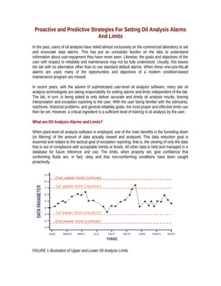
  • 1. Proactive and Predictive Strategies For Setting Oil Analysis Alarms And Limits In the past, users of oil analysis have relied almost exclusively on the commercial laboratory to set and enunciate data alarms. This has put an unrealistic burden on the labs to understand information about user-equipment they have never seen. Likewise, the goals and objectives of the user with respect to reliability and maintenance may not be fully understood. Usually, this leaves the lab with no alternative other than to use standard default alarms. When these one-size-fits-all alarms are used, many of the opportunities and objectives of a modern condition-based maintenance program are missed. In recent years, with the advent of sophisticated user-level oil analysis software, many site oil analysis technologists are taking responsibility for setting alarms and limits independent of the lab. The lab, in turn, is being asked to only deliver accurate and timely oil analysis results, leaving interpretation and exception reporting to the user. With the user being familiar with the lubricants, machines, historical problems, and general reliability goals, the most proper and effective limits can then be set. However, a critical ingredient is a sufficient level of training in oil analysis by the user. What are Oil Analysis Alarms and Limits? When plant-level oil analysis software is employed, one of the main benefits is the funneling down (or filtering) of the amount of data actually viewed and analyzed. This data reduction goal is essential and relates to the tactical goal of exception reporting, that is, the viewing of only the data that is out of compliance with acceptable trends or levels. All other data is held and managed in a database for future reference and use. The limits, when properly set, give confidence that conforming fluids are, in fact, okay and that non-conforming conditions have been caught proactively. FIGURE 1 Illustration of Upper and Lower Oil Analysis Limits
  • 2. Because the goals and expectations vary considerably from one organization to another these limits are best set by those charged with the responsibility of machine reliability and long fluid life. They are also influenced by machine and application specific considerations. For instance, where the gear box loads and duty cycle are low in one application, they may exceed rated levels in another. The availability of spares and standby equipment may influence the decision with equal magnitude. And, the age of the machine or lubricant may impact the placement of limits in certain cases. Basically, a limit or alarm is a strategically placed "trip wire" that alerts you to an abnormal condition. Some data parameters have only upper limits such as particle counts or wear debris levels. A few data parameters apply a few lower limits like TBN, additive elements, flash point, and FTIR (additive). Other data parameters use both upper and lower limits. These might relate to important chemical and physical properties of the lubricant such its viscosity (see Figure 1). The computer trends the data and normally no alarm is reported as long as the limits are not exceeded. When an exception exists the software is designed to alert and direct corrective action in response to the deleterious result. To insure maximum benefit from oil analysis, careful thought needs to go into the type of limit used and its setting. Some Limits are More Proactive Proactive limits are designed to alert users to abnormal machine conditions associated with root causes of machine and lubricant degradation. They are keyed to the proactive maintenance philosophy of setting targets (or standards) and managing the lubricant conditions to within the targets. A strategic premise is that these conditions are controlled to levels that are improvements over past levels and that these become goals. Best results occur when progress towards achieving these goals are charted conspicuously by the maintenance organization. These types of limits are referred to as "goal-based," see Figure 2. FIGURE 2 Goal-Based Limits Are Set For Certain Data Parameters To Proactively Improve Machine And Lubricant Reliability
  • 3. In order to set a goal-based limit a level of machine reliability is identified. Again, this needs to be an improvement over previous levels. If, for instance, we use particle count as the parameter then we need to select a "target cleanliness" which is a marked improvement from before. The target cleanliness becomes the limit. In the example, if previously contaminant levels were averaging about ISO 18/15 for a hydraulic system, a limit set at 15/12 would be a goal-based improvement. A life extension of three times (MTBF) would be expected based on controlled field studies. If, on the other hand, we set a limit of 18/15 our effort is downgraded to the detection of major faults only. Goal-based limits of this type can be applied to particle counts, moisture levels, glycol levels, fuel dilution, TAN, and other common failure root cause conditions. Another similar type of proactive limit relates to the progressive aging of the lubricant or hydraulic fluid. From the moment the oil is first put into service its physical and chemical properties transition away from the ideal (i.e., those of the new formulated oil). For some properties the transition may be extremely slow but for others it can be abrupt and dynamic. Limits keyed to the symptoms of lubricant deterioration are referred to as "aging limits," see Figure 3. They are designed to signal the need for a well-timed condition-based oil change and are usually pegged to the depletion of additives and the thermal/oxidative degradation of the base oil. FIGURE 3 :Aging-Limits Are Keyed To Degrading Additive Base-Stock Properties In order to properly set aging limits the new lubricant must be analyzed to reveal its physical and chemical properties. This will become the oil's "base signature." Care must be taken to insure that the new oil is analyzed using the same test procedures and instruments that will be used to analyze the used oil. Under no circumstances should these "base signature" properties be simply lifted off the lubricant's spec sheet as provided by the supplier. Instruments and test methods vary substantially and new oils are approved if their properties fall within a tolerance range. For instance, ISO viscosity grades vary plus/minus ten percent from a nominal center point (grade). This means that a VG 68 lubricant would be "in grade" from 61 to 75 centistokes (cSt). This is too much variance for 68 centistokes to serve as a proper baseline. However, if the actual viscosity of
  • 4. a specific lubricant was measured and found to be 64 cSt then a precise baseline is now available against which the used oil can be trended. Aging limits can be effectively applied to such parameters as TAN, TBN, viscosity, RBOT, emission spectroscopy for additive elements, FTIR (for oxidation, nitration, & sulphation), and dielectric constant. Aging limits often follow trendable data patterns, i.e., they trend steadily in the direction of the limit. The actual time to limit might be predicted by linear or non-linear regression; a feature in some oil analysis software products. For instance, the following equation might be applied to estimate the remaining useful life of a turbine oil using Rotating Bomb Oxidation Test (RBOT): Lower aging limits are generally set for additive depletion, RBOT life, and TBN. Upper limits are set for dielectric constant, TAN, and FTIR for oxidation, sulphation, and nitration trends. And both upper and lower limits should be set for viscosity. The table in Figure 4 shows some example limits for both goal-based and aging parameters. FIGURE 4 Example of Goal-Based Limits Other Limits are More Predictive Predictive limits are set to signal the presence of machine faults or abnormal wear conditions. They are aligned with the goals of predictive maintenance, i.e., the early detection of machine failure symptoms as opposed to failure root causes (proactive maintenance). In oil analysis, a proper predictive limit set to the correct parameter has many advantages over other predictive maintenance technologies. Specifically, it offers reliable incipient fault detection, spanning a wide range of machine failure modes. It is seer-like in that it has the ability to forecast a future event. As compared to vibration analysis for instance, the time-based detection window using ferrous density analysis has been demonstrated to exceed 15 times for common gear boxes failures. Rate-of-change limits are generally identified as predictive. These are set to a property that is being progressively introduced to the oil, such as wear debris. The add rate (change) might be calculated per unit time, for instance ppm iron per 100 hours on oil. When the parameter's value is plotting against time the rate-of-change (add rate) equates to the current slope of the curve. As an
  • 5. alternative to representing rate-of-change, slope can be quantified by dividing rise by run for a fixed period of time (see Figure 5). The linear trends also points to the approximate time interval remaining before a level-type limit is exceeded. Unlike level limits however, rate-of-change limits ignore the absolute value of a data parameter, emphasizing instead the speed (rate) at which the level is changing. This can be best illustrated by an example. Suppose for a given machine, such as an industrial gear unit, iron is typically introduced to the oil at roughly 5 ppm per month. The first month after an oil change the iron shows 5 ppm, the expected level. After the second month the iron shows 10 ppm, again this is expected (5 + 5). The same holds for the end of the third month when 15 ppm is reported. The add rate of 5 ppm per month remains uninterrupted. However, by the end of the fourth month the unexpected result of 50 ppm is obtained. The computer software shows this as a critical. The reason is not due to the fact that 50 ppm in a gear lube signals abnormal wear. In fact this is a rather common iron concentration in gear oils. However, the alarm is responding to the rate at which the iron concentration changed in the last month of service (35 ppm instead of the expected 5 ppm). Had rate-of-change limits not been applied this exception might not have been reported. FIGURE 5 Using Rate-of-Change Limits (rise/run) Must Be Calculated For The Trending Data Parameter The use of rate-of-change limits is well suited for wear debris analysis but can be used for other parameters as well. Examples of where it is commonly applied include particle counts, elemental wear metals, ferrous density analysis (DR, PQ 90, Wear Particle Analyzer, ferrous Contam-Alert), TAN, and RBOT. It should be noted that multiple limit strategies can be used for single test parameters, i.e., where rate-of-change limits are applied so too are level limits (aging, proactive, and statistical).
  • 6. Statistical Limits are Predictive as Well For many years statistical limits have been used successfully in oil analysis. The practice requires the availability of a certain amount of historical data on the target parameters (see Figure 6). A population standard deviation is calculated. Upper limits are then set relating to the number of standard deviations (sigmas) above the sample population average. Many analysts put a caution at one or two sigmas and a critical at two or three sigmas. When one sigma is exceeded this means that the value from the test result exceeds 68 percent of historical samples. A result that alarms at two sigmas exceeds 95 percent of historical data. Three sigma exceedance corresponds to of 99.7 percent of the database. Many commercial laboratories have large repositories of data spanning numerous machine types and models. These data permit the relatively easy calculation of national averages and corresponding population standard deviations (sigmas). In some cases the data can be conveniently sorted according to industry and application. These same databases can be used to assist in the setting of rate-of-change limits as well. Typical applications of statistical limits include elemental analysis of wear metals, ferrous density analysis (DR, PQ 90, etc.), and other common predictive oil analysis measures. It is well known that many machines exhibit highly individual characteristics. They might trend high or low when compared to national averages. Data from a machine that is a low reader might not alarm early enough when national averages are used as the statistical base (false negative). Likewise, when a high reader is encountered (potential false positive), it may be well advised to adjust the statistical limit accordingly, or simply rely more heavily on rate-of-change limits. FIGURE 6 Statistical Limits Are Keyed To Historical Oil Analysis Trends Dealing With Data Noise Data noise can mask or distort the target data parameter (and trend) often making it nearly invisible to detection. And, when data noise exists it can inhibit the ideal placement of certain alarms and
  • 7. limits. A machine that normally has a high level of wear particles in its lubricating oil is a good example. These particles do not represent current wear activity but are an accumulation of historical wear, possibly going back many months. This is a common situation when course filters or no filters are in use. This high concentration of wear particles constitutes noise for an oil analysis program. FIGURE 7 Clean Fluids Help Provide Improved Fault Detection Sensitivity While the target signal (data) is current wear levels, these particles may be extremely difficult if not impossible to measure when they are mixed indiscriminately with historical wear debris. This equates to low signal-to-noise ratio. Crudely stated the fault signal is getting lost in the sauce. This situation is illustrated in Figure 7. When particle concentrations are controlled to an ISO 19/16 fault detection is poor. By comparison, the ISO 13/10 fluid translates to high-resolution detection, i.e., high signal-to-noise ratio. A similar problem occurs with infrared spectroscopy when weak absorption signals are lost due to inaccurate reference spectra and the presence of interfering materials in oil. Summary With the current trend of users taking control of the their oil analysis programs there has been a surge of interest in education. This has recently lead to an STLE (Society of Tribologist and Lubrication Engineers) committee being formed to offer oil analysis certification levels. While oil analysis education is often aimed at data interpretation it is no less important in the area of limit setting. In fact, limit setting and data interpretation are co-mingled activities. When oil analysis limits are properly set and the correct tests are performed at the right frequency, data interpretation is easy and efficient. The strategic use of goal-based and aging limits enables proactive maintenance to be carried out at the highest level. Likewise, when rate-of-change and statistical limits are deployed, the benefits of early fault detection are achieved. The combination of these limit-setting strategies affords the broadest and most effective protection for the plant equipment and its lubrication assets.
  • 8. Clean Oil Sampling How to Sample Oil Without Opening the Bottle Proper oil sampling does not have to be a difficult or unpleasant experience. In fact, when the best sampling methods (and hardware) are employed the experience should be just the opposite. There are many important lessons to learn when it comes to pulling a sample. Many run contrary to intuition. Most of them have to do with insuring that what enters the bottle is both rich in information and remains undisturbed by the sampling process itself. It is this later concern that is addressed by this article. Modern oil analysis programs typically include some tests that can be influenced by environmental contaminants entering the oil (bottle) during the sampling process. Tests of greatest risk include particle counting, elemental spectroscopy, and total acid number. In situations where there is considerable dust in the environment at the time the sample is pulled, a concerted effort needs to be made to insure that this dust does not contaminate the oil. Examples of high-risk situations/environments include mine sites, construction sites, primary metals industries, foundries, windy outdoor conditions, and sample points close to the ground. Experiments on the influence of environmental dust on particle counts have shown a marked effect. It is not unusual for an oil’s ISO code to increase 2-3 range numbers when a bottle is left open just a few minutes. For instance, the actual oil sampled might be a rather clean ISO 13/10 but after exposing the sample bottle to atmosphere it can show an ISO 16/13. The amount of dirt needed to accomplish an ISO 16/13 is only about 1 ppm. Recently, a new method called “clean oil sampling” has emerged that greatly simplifies the process and minimizes the risk of dirt entering the bottle. It involves the use of common zip-lock sandwich bags and sampling hardware such as vacuum pumps and probe devices. Below is an outline description of this procedure: Step One Obtaining a good oil sample begins with a bottle of the correct size and cleanliness. The topic of bottle cleanliness will be discussed in greater detail in a future issue of Practicing Oil Analysis. However, it is understandable that the bottle must be at a known level of cleanliness and that this level should be sufficiently high so as not to interfere with expected particle counts.
  • 9. Some people relate this to a signal-to-noise ratio, i.e., the target cleanliness level of the oil (signal) should be several times the expected particle contamination of the bottle (noise). For more information on bottle cleanliness refer to ISO 3722. StepTwo Before going out into the plant with the sample bottles place the capped bottles into very thin zip-lock sandwich bags; one per bag. Zip each of the bags such that air is sealed into the bag along with the bottles. This should be done in a clean-air indoor environment in order to avoid the risk of particles entering the bags along with the bottles. After all of the bottles have been bagged, put these small bags (with the bottles) into a large zip-lock bag for transporting them to the plant or field. Sampling hardware such as vacuum pumps and probe devices should be placed in the large bag as well. Step Three After the sampling port or valve has been properly flushed (including the sampling pump or probe if used) remove one of the bags holding a single sample bottle. Without opening the bag, twist the bottle cap off and let the cap fall to the side within the bag. Then move the mouth of the bottle so that it is away from the zip-lock seal. Do not unzip the bag. Step Four Thread the bottle into the cavity of the sampling device (vacuum pump or probe). The plastic tube will puncture the bag during this process, however, try to avoid other tears or damage to the bag (turn the bottle, not the probe or pump, while tightening). If a probe device is used, it is advisable to break a small hole in the bag below the vent hole with a pocket knife. This permits air to escape during sampling. Step Five The sample is then obtained in the usual fashion until the correct quantity of oil has entered the bottle. Next, by gripping the bottle, unscrew it from the cavity of the pump or probe device. With the
  • 10. bottle free and still in the bag, fish the cap from the bottom of the bag onto the mouth of the bottle and tighten. Step Six With the bottle capped it is safe to unzip the bag and remove the bottle. Confirm that the bottle is capped tightly. The bottle label should be attached and the bottle placed in the appropriate container for transport to the lab. Do not reuse the zip-lock bags. Benefits of Clean Oil Sampling This simple procedure effectively permits samples to be obtained without exposing the fluid or the bottle to the atmosphere or surface contamination. A clean sample can even be obtained with dirty hands. There are no expensive materials to purchase and the technique can be applied to a large number of sampling situations. For best results practice a few times with a spare bottle until the technique is perfected.
  • 11. What Particles Mean and Why They Need to be Monitored and Controlled With the widespread use of plant-level particle counters, maintenance organizations are increasingly more sophisticated and skilled in the management and control of oil cleanliness. This has led to the discovery of a host of new tactics and practices in combining the particle counter with other important onsite oil analysis tools and methods; many unheard of just a few years ago. Contamination can be defined as any unwanted substance or energy that enters or contacts the oil. Contaminants can come in a great many forms, some are highly destructive to the oil, its additives, and machine surfaces. It is often overlooked as a source of failure because its impact is usually slow and imperceptible yet, given time, the damage is analogous to eating the machine up from the inside out. While it is not practical to attempt to totally eradicate contamination from in-service lubricants, control of contaminant levels within acceptable limits is accomplishable and vitally important. Particles, moisture, soot, heat, air, glycol, fuel, detergents, and process fluids are all contaminants commonly found in industrial lubricants and hydraulic fluids. However, it’s particle contamination that is widely recognized as the most destructive to the oil and machine. This explains why the particle counter is the most widely used instrument in oil analysis today. And, the central strategy to its success in reducing maintenance costs and increasing machine reliability is proactive maintenance. Proactive Maintenance. While the benefits of detecting abnormal machine wear or an aging lubricant condition are important and frequently achieved with oil analysis programs, they should be regarded as low on the scale of importance compared to the more rewarding objective of failure avoidance. This is achieved by treating the causes of failure, not simply the symptoms. And,is is the foundation of the popular practice known as proactive maintenance. In fact, the only effective way to obtain simple solutions to complex machine maintenance problems is through proactive maintenance. Whenever a proactive maintenance strategy is applied, three steps are necessary to insure that its benefits are achieved. Since proactive maintenance, by definition, involves continuous monitoring and controlling of machine failure root causes, the first step is simply to set a target, or standard, associated with each root cause. In oil analysis, root causes of greatest importance relate to fluid contamination (particles, moisture, heat, coolant, etc.). However, the process of defining precise and challenging targets (e.g., high cleanliness) is only the first step. Control of the fluid's conditions within these targets must then be achieved and sustained. This is the second step and often includes an audit of how fluids become contaminated
  • 12. and then systematically eliminating these entry points. Often better filtration and the use of separators are required. The third step is the vital action element of providing the feedback loop of an oil analysis program. When exceptions occur (e.g., over target results) remedial actions can then be immediately commissioned. Using the proactive maintenance strategy, contamination control becomes a disciplined activity of monitoring and controlling high fluid cleanliness, not a crude activity of trending dirt levels. Finally, when the life extension benefits of proactive maintenance are flanked by the early warning benefits of predictive maintenance, a comprehensive condition-based maintenance program results. While proactive maintenance stresses root-cause control, predictive maintenance targets the detection of incipient failure of both the fluid's properties and machine components like bearings and gears. It is this unique, early detection of machine faults and abnormal wear that is frequently referred to as the exclusive domain of oil analysis in the maintenance field. Managing Particle Contamination. There is no single property of lubricating oil that challenges the reliability of machinery more than suspended particles. It would not be an exaggeration to refer to them as a microscopic wrecking crew. Small particles can ride in oil almost indefinitely and because they are not as friable (easily crumbled) as their larger brothers, the destruction can be continuous. Many studies have shown, with convincing evidence, the greater damage associated with small particles. Still, most maintenance professionals have misconceptions about the size of particles and the associated harm caused. These misconceptions relate to the definition people apply to what is clean oil and what is dirty oil. And, it is this definition that influences the setting of appropriate target cleanliness levels for lubricating oils and hydraulic fluids. The process is not unlike a black box circuit. If we want a change to the output (longer and more reliable machine life) then there must be a change to the input (a lifestyle change, i.e., improved cleanliness). For instance, it’s not the monitoring of cholesterol that saves us from heart decease, instead it's the things we do to lower the cholesterol. Therefore the best target cleanliness level is one that is a marked improvement from historic levels. While there are numerous different methods used to arrive at target cleanliness levels for oils in different applications, most combine the importance of machine reliability with the general contaminant sensitivity of the machine to set the target. The Reliability Penalty Factor and the Contaminant Severity Factor are arrived at by a special scoring system that is included with the Target Cleanliness Grid. There are many expensive ways to achieve clean oil but experience has taught us the wisdom of contaminant exclusion–treating the cause not just the symptom. By effectively excluding the entry of contaminants and promptly removing contaminants when they do enter, the new cleanliness targets are frequently achieved. Concerns that filtration costs will increase are not often realized due to the greater overall control, especially from the standpoint of particle ingression. Particle Counting—The "Invisible" Filter. Engineers learn that "controlled systems" are those that have feedback loops. In proactive maintenance this is the monitoring step, i.e., particle
  • 13. counting. If this is done on a frequent enough basis, not only is proactive maintenance achieved but also a large assortment of common problems can be routinely detected. As such, particle counting is an important "catch all" type test. Because of the obvious value, it is not uncommon to find organizations testing the cleanliness of their oils as frequently as weekly. The activity of routine particle counting has a surprising impact on achieving cleaner oils. When the cleanliness of oil's are checked and verified on a frequent basis a phenomena known as the "invisible filter" occurs, which is analogous to the saying, "what gets measured gets done." Because a great deal of dirt and contamination that enters oils often come from the careless practices of operators and craftsmen, the combined effect of monitoring with a modicum of training can go a long way toward achieving cleanliness goals. The following are common proactive and predictive maintenance uses of an onsite particle counter: Proactive Maintenance: 1. Routinely verify that in-service oils are within targeted cleanliness levels. 2. Check the cleanliness of new oil deliveries. 3. Quickly identify failed or defective filters. 4. Confirm that seals and breathers are keeping contaminants out. 5. Confirm that systems are properly cleaned and flushed after repair. 6. Confirm that new machines are cleaned and flushed before use. 7. Identify the use of dirty top-up containers and poor maintenance practices. 8. Identify the timing for filter cart use. Predictive Maintenance: 1. Identify early-stage abnormal machine wear with quick confirmation by repeating. 2. Identify the location/source of abnormal wear by multi-point isolating methods. 3. Verify the effectiveness of corrective maintenance and botched repair jobs. 4. Monitor machine break-in wear generation. 5. Identify abnormal rust and corrosion products in the oil. 6. Assist in confirming machines are balanced and aligned. 7. Permit more "on-condition" laboratory oil analysis. 8. Serve as an effective screen for wear debris analysis. There are many different types of automatic particle counters used by oil analysis laboratories. There are also a number of different portable particle counters on the market. The performance of these instruments can vary considerably depending on the design and operating principle. Particle counters employing laser or white light are widely used because of their ability to count particles across a wide range of sizes. Pore-blockage type particle counters have a more narrow size range sensitivity; however, they're also popular because of their ability to discriminate between hard particles of other impurities in the oil. When good procedures and practices are followed, both types of particle counters provide value and effectiveness in maintenance applications.
  • 14. Figure 2 shows how particle count trends vary depending on the machine application and the presence of an onboard filter. Because particle counters monitor particles in the general size range controlled by filters, equilibrium is usually achieved, i.e., particles entering the oil from ingression minus particles exiting from filtration will leave behind a steady-state concentration. When filters are properly specified and ingression is under control this steady-state concentration will be well within the cleanliness target. Systems with no continuous filtration, e.g., a splash-fed gearbox, the equilibrium is not effectively established (there is no continuous particle removal). This causes the particle concentration to be continuously rising. Still, contamination control can be achieved by periodic use of portable filtration systems like a filter cart. By combining the use of a particle counter with other onsite oil analysis tools, particle count trends can be more effectively interpreted. Figure 3 shows how particle count trends from a circulating industrial gearbox can be monitored and interpreted when ferrous density analysis is added as an exception test. Ferrous density analysis instruments are sold by several suppliers and include DR ferrograph, Particle Quantifier, and Ferrous Particle Counter. Figure 4 shows how particle trends can be compared to viscosity trends to reveal a host of crankcase lubrication problems. Training—Key to Success. Like most activities in oil analysis and maintenance technology, success in particle counting and contamination control requires education and skill development. Unless maintenance professionals have an understanding of the purpose and goals of oil analysis and are literate in the language of oil analysis, they cannot be expected to carry out its mission. This is accomplished through a liberal amount of training and education. And, this should not simply be concentrated on a single individual but should be spread about to all those that benefit from and contribute to machine reliability. In fact, training and education should occur at several different levels including craftsmen, operators, engineering, and management. Below are a few subjects for which seminars and training classes are generally available: Figure 2 Figure 3 Figure 4
  • 15. 1. Lubrication fundamentals and their use 2. Mechanical failure analysis 3. Proactive maintenance and root cause analysis 4. Troubleshooting hydraulic systems 5. Lubrication and maintenance of bearings and gear units 6. Oil analysis fundamentals 7. Oil analysis data interpretation 8. Filtration and contamination control 9. Wear particle analysis machine fault detection Once these fundamentals are in place, oil analysis can move forward enthusiastically, beginning with the development of its mission and goals. And, instead of indifference to oil analysis exceptions, rapid-fire corrections are carried out and measures are taken to preempt their reoccurrence. In time, unscheduled maintenance becomes rare and oil analysis exceptions are few as the idealized machine operating environment becomes controlled. Finally, as the many elements of oil analysis and proactive maintenance merge together into a cohesive maintenance activity, the benefits should not be allowed to go unnoticed. Unlike many applications of new technology, proactive maintenance seeks non-events as its goal and reward. These non-events include oil that continues to be fit-for-service, machines that don't break down, and inspections that don't need to be performed. This quiet existence is the product of a highly disciplined activity but, at times, can be misunderstood by the casual observer as unneeded. Therefore, the close association of the activities of proactive maintenance with the benefits of proactive maintenance must be measured, monitored, and displayed for all to view.