Canal drop notch type -design steps
•
0 likes•1,296 views

Canal fall Notch Type design steps

Recommended
More Related Content
What's hot
What's hot (20)
Similar to Canal drop notch type -design steps
Similar to Canal drop notch type -design steps (20)
Recently uploaded
Recently uploaded (20)
Canal drop notch type -design steps
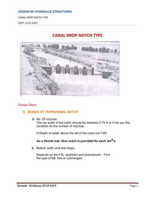
- 1. DESIGN OF HYDRAULIC STRUCTURES CANAL DROP-NOTCH TYPE DEPT. of CE,VAST Nirmala Krishnan, AP CE VAST Page 1 CANAL DROP-NOTCH TYPE Design Steps I) DESIGN OF TRAPEZOIDAL NOTCH a. No. Of notches The top width of the notch should lay between 0.75 H to H-As per this condition fix the number of notches- H-Depth of water above the sill of the notch-u/s FSD As a thumb rule -One notch is provided for each 2m3/s b. Bottom width and side slope Depends on the FSL upstream and downstream . . Find the type of fall, free or submerged.
- 2. DESIGN OF HYDRAULIC STRUCTURES CANAL DROP-NOTCH TYPE DEPT. of CE,VAST Nirmala Krishnan, AP CE VAST Page 2 a) Free fall Take C d=0.962 or 0.7 L-base width of the notch-length of the sill d- depth of water in meters. For full supply condition take Q=Q, d = d(FSD) For half supply condition Q=0.5Q, d=0.75 d (HSD) If not given, assume a minimum of 1m for calculation Form two equations and solve for L and n b) For submerged fall
- 3. DESIGN OF HYDRAULIC STRUCTURES CANAL DROP-NOTCH TYPE DEPT. of CE,VAST Nirmala Krishnan, AP CE VAST Page 3 fix the dimensions of the notch 2) Design of drop wall Length of drop wall i) >7/8 times the u/s canal width ii) <bed width of the downstream canalTop width of the notch L’=L + n d Find the total top width =L’ X no. of notches Find the remaining length. Distribute the length between the notches 1) Thickness at the top of the drop wall . b = ((d/2) +0.15) to ((d/2)+0.3 ) meters .d= depth of flow over notch ie FSD of the U/S canal 2) Height of the drop wall Depends on the depth of water cushion that is to be provided atthe d/s of the canal, it can be calculated from
- 4. DESIGN OF HYDRAULIC STRUCTURES CANAL DROP-NOTCH TYPE DEPT. of CE,VAST Nirmala Krishnan, AP CE VAST Page 4 (d1+x)-effective depth of water cushion X-depth of water cushion below the bed of channel downstream . d1 -FSD of the channel D/S . dc -FSD of the U/S canal . h- Depth drop-difference in FSD of the U/S and D/S canalFind x Find (d1+x)-fix the bottom level wrt D/S side-ie T/L of solid apron Find the height of the drop wall wall=u/s canal B/L-T/L of solid apron 3) Bottom width of drop wall H-height of drop wall h- Height of water falling over the notch=U/S FSD G-sp.gr of masonry. =2.25
- 5. DESIGN OF HYDRAULIC STRUCTURES CANAL DROP-NOTCH TYPE DEPT. of CE,VAST Nirmala Krishnan, AP CE VAST Page 5 3). Design of water cushion cistern i) Length of floor from the toe of the drop wall Subject to a minimum of ii) Thickness of cushion ie solid apron, Depends upon the hard soil strata Assume a thickness; check it with Bligh’s creep theory and t min Based on Bligh’s creep theory. Maximum uplift head =diff. in W/L of U/S and D/S canal Assume a thickness say 1m Assume a hydraulic gradient of 1 in 4 Bligh’s creep coeff, C=1/HG Total creep length =AB+BC+CD (ref fg) Head lost =creep length/C Residual head, h =max. uplift head-head lost Thickness required = h / (ƿ-1), ƿ=2.24
- 6. DESIGN OF HYDRAULIC STRUCTURES CANAL DROP-NOTCH TYPE DEPT. of CE,VAST Nirmala Krishnan, AP CE VAST Page 6 Minimum thickness required t min = Whichever is higher provide that thickness, check with site conditioncheck for residual uplift. Check for residual head at the end of the solid Apron The downstream end of the water cushion must be built with A slope of 1 in 5, so that stone and other debris carried to thecistern must be washed out 4) Design of notches and notch pier 1. Sill of notches-at B/L of channel U/S 2. Top level of notches-FSL on U/S canal3 .Width of notch pier -FSD/2 3. Top width >FSD/2 of U/S channel Sketch include 5. Protective Works
- 7. DESIGN OF HYDRAULIC STRUCTURES CANAL DROP-NOTCH TYPE DEPT. of CE,VAST Nirmala Krishnan, AP CE VAST Page 7 1. Abutment BC Length=width of drop wall at foundation Top width of abutment=0.5m T/L of abutment =TBL of channel D/S. Provide 1 in 8 slope Foundation is a continuous structure of drop wall with thickness 1m. Find the height H Base width =0.4 H 2 .Upstream wing wall Top level =TBL of channel U/STop width =0.5m
- 8. DESIGN OF HYDRAULIC STRUCTURES CANAL DROP-NOTCH TYPE DEPT. of CE,VAST Nirmala Krishnan, AP CE VAST Page 8 Splay 1 in 1 Foundation not as deep as abutment Check for hard soil, fix the B/L of foundation slab thickness=0.5m 4.D/S of wing wall Top Level-TBL of D/S channel. Top width =0.5m Front batter =1 in 8 Foundation depends on channel D/S Foundation slab provide 60cm thickness Splay 1 in 1. 5) Pitching 1) Length of revetment and bed pitching a) U/S-measured from the face of the drop walllength =3FSD or minimum 3m c) D/S-measured from D/S edge of solid apron Length =4(FSD +height of drop) or min 6m 2) Bed pitching Provide half the length of the corresponding revetments.
- 9. DESIGN OF HYDRAULIC STRUCTURES CANAL DROP-NOTCH TYPE DEPT. of CE,VAST Nirmala Krishnan, AP CE VAST Page 9