2. grown from graphite oxide (GO),7 which can subse-
quently be reduced electrochemically to make electroni-
cally conducting graphitic films. In their work, GO
nanoparticles were prepared from synthetic graphite.
They noted that the multilayer films consisted of
incompletely exfoliated platelets that were tens of
nanometers in their lateral dimensions. In this paper,
we revisit the assembly of GO/polycation thin films,
using GO prepared from natural crystals. We show that
exfoliated GO derived from these crystals is a mechani-
cally robust material that deposits conformally on
cationic surfaces as micron-sized, nanometer-thick sheets.
Graphite oxide is a pseudo-two-dimensional solid in
bulk form, with strong covalent bonding within the
layers. Weak interlayer contacts are made by hydrogen
bonds between intercalated water molecules.8-11 The
carbon sheets in GO contain embedded hydroxyl and
carbonyl groups, as well as carboxyl groups situated
mainly at the edges of the sheets.8,9,12 While there is no
consensus as to the precise structure of GO layers,
different structural models,9a,b,10 which correspond to an
ideal formula of C8O2(OH)2, have been advanced. A
recent study of the structure of GO argues from 13C and
1H NMR evidence for the presence of epoxy groups.13
Nakajima and co-workers have proposed that the carbon
layers in GO are linked together in pairs by sp3 C-C
bonds perpendicular to the sheets.10 According to Kli-
nowski et al.,13 the carbon layers in GO contain two
kinds of domains, aromatic regions with unoxidized
benzene rings and aliphatic regions with six-membered
carbon rings. The relative size of the domains, which
are randomly distributed, depends on the degree of
oxidation. In both models, the hydroxyl groups project
above and below the carbon grid. The phenolic hydroxyl
groups are acidic and, together with the carboxyl groups,
are responsible for the negative charge on the GO sheets
in aqueous suspensions.9,13 The surface charge density
of colloidal GO particles (degree of oxidation 85%) was
measured by Fendler and co-workers as 0.4 per 100 Å2.7
The GO interlayer distance is not constant and
depends strongly on the GO:H2O ratio.8-10,15 In very
dilute aqueous suspensions, the interlayer distance is
large, so interaction between the layers is sufficiently
weak that exfoliation occurs.8 Our previous research
showed that the number of layers in the GO colloidal
particles can be controlled by the dilution of the suspen-
sions.16,17 The adsorption capacity for Cu(II) ions, which
was for both aqueous suspensions16 and thin films
deposited from these suspensions on powder supports
(ZnO, Al2O3, fumed SiO2),17 increased with decreasing
GO concentration in the starting suspension. For ex-
ample, the adsorption capacity of GO films on SiO2
increased by a factor of 2.4 when the GO concentration
in the starting suspension was decreased from 1.0 to
0.3 g/L. This result shows that more complete exfoliation
provides increased access to the GO functional groups.
For samples prepared from the colloids with GO con-
centrations of 0.02-0.3 g/L, the maximum adsorption
capacity, 22-24 mmol/g, was obtained. This value is
close to the total quantity of oxygen-containing groups
in GO (25 mmol/g9) and gives indirect evidence that
dilute GO colloids are exfoliated as monolayers.
We report here a detailed study of the preparation
and characterization of GO/polycation films grown on
planar Si and Al2O3/Al supports. Using atomic force
microscopy (AFM), ellipsometry, and electrical mea-
surements, the following questions have been addressed:
What does the first layer of the sheets adsorbed on a
substrate look like microscopically?
Can we affect the quality of mono- and multilayer
films by varying the conditions of their deposition and
the chemical composition of the substrate surface?
What are the electronic properties of GO/polycation
films, and how are they influenced by the nature of the
polycation?
Experimental Section
Materials. GO was synthesized from natural graphite
powder (325 mesh, GAK-2, Ukraine) by the method of Hum-
mers and Offeman.18
It was found that, prior to the GO
preparation according to ref 18, an additional graphite oxida-
tion procedure was needed. Otherwise, incompletely oxidized
graphite-core/GO-shell particles were always observed in the
final product. The graphite powder (20 g) was put into an 80
°C solution of concentrated H2SO4 (30 mL), K2S2O8 (10 g), and
P2O5 (10 g). The resultant dark blue mixture was thermally
isolated and allowed to cool to room temperature over a period
of 6 h. The mixture was then carefully diluted with distilled
water, filtered, and washed on the filter until the rinse water
pH became neutral. The product was dried in air at ambient
temperature overnight. This preoxidized graphite was then
subjected to oxidation by Hummers’ method. The oxidized
graphite powder (20 g) was put into cold (0 °C) concentrated
H2SO4 (460 mL). KMnO4 (60 g) was added gradually with
stirring and cooling, so that the temperature of the mixture
was not allowed to reach 20 °C. The mixture was then stirred
at 35 °C for 2 h, and distilled water (920 mL) was added. In
15 min, the reaction was terminated by the addition of a large
amount of distilled water (2.8 L) and 30% H2O2 solution (50
mL), after which the color of the mixture changed to bright
yellow. The mixture was filtered and washed with 1:10 HCl
solution (5 L) in order to remove metal ions. The GO product
was suspended in distilled water to give a viscous, brown, 2%
dispersion, which was subjected to dialysis to completely
remove metal ions and acids. The resulting 0.5% w/v GO
dispersion, which is stable for a period of years, was used to
prepare exfoliated GO.
Exfoliation was achieved by dilution of the 0.5% GO disper-
sion (1 mL) with deionized water (24 mL), followed by 15 min
sonication. The resulting homogeneous yellow-brown sol,
which contained 0.2 g/L GO, was stable for a period of months
and was used for film preparation.
An aqueous solution (0.01 M) of poly(allylamine hydrochlo-
ride), PAH, (Aldrich, MW ) 50 000-65 000) was adjusted to
pH 7 with NH3 and was used for growth of polycation layers.
(7) (a) Kotov, N. A.; Dekany, I.; Fendler, J. H. Adv. Mater. 1996, 8,
637. (b) Cassagneau, T.; Fendler, J. H. Adv. Mater. 1998, 10, 877.
(8) (a) Thiele, H. Kolloid-Z 1948, 111, 15. (b) Croft, R. C. Quart.
Rev. 1960, 14, 1.
(9) (a) Scholz, W.; Boehm, H. P. Z. Anorg. Allg.Chem. 1969, 369,
327. (b) Clauss, A.; Boehm, H. P.; Hofmann, U. Z. Anorg. Allg.Chem.
1957, 291, 205.
(10) Nakajima, T.; Mabuchi, A.; Hagiwara, R. Carbon 1988, 26, 357.
(11) Karpenko, G.; Turov, V.; Kovtyukhova, N.; Bakai, E.; Chuiko,
A. Theor. Exp. Chem. (Russ.) 1990, 1, 102.
(12) Hadzi, D.; Novak, A. Trans. Faraday. Soc. 1955, 51, 1614.
(13) Lerf, A.; He, H.; Forster, M.; Klinowski, J. J. Phys. Chem. B
1998, 102, 4477.
(14) Hennig, Z. Progr. Inorg.Chem. 1959, 1, 125.
(15) Lagow, R. J.; Badachhape, R. B.; Wood, J. L.; Margrave, J. L.
J. Chem. Soc. Dalton 1974, 1268.
(16) Kovtjukhova, N. I.; Karpenko, G. A. Mater. Sci. Forum 1992,
91-93, 219.
(17) (a) Kovtyukhova, N. I.; Chuiko, A. A. Abstracts; Fall Meeting
of the Materials Research Society, 1994, Boston, C9.6. (b) Kovtyukhova,
N. I.; Buzaneva, E. V.; Senkevich, A. Carbon 1998, 36, 549. (18) Hummers, W.; Offeman, R. J. Am. Chem. Soc. 1958, 80, 1339.
772 Chem. Mater., Vol. 11, No. 3, 1999 Kovtyukhova et al.
3. An aqueous solution of doped polyaniline (PAN) was made
from a saturated solution of the emeraldine base form in
dimethylformamide. A 3 mL portion of this solution was slowly
added with stirring to 26 mL of water, which had been acidified
to pH 3.5 with aqueous HCl. The pH of the final PAN solution
was then adjusted to 2.5 by addition of aqueous HCl. The alu-
minum Keggin ion Al13O4(OH)24(H2O)12
7+ was prepared trom
Al13O4(OH)25(H2O)11(SO4)3‚x(H2O), which was available from
a previous study.5 Briefly, 0.102 g of the sulfate salt was added
to a solution of 0.042 g of BaCl2 in 200 mL of water and stirred
overnight. The resulting 0.3 mM solution of the chloride salt
of the aluminum Keggin ion was filtered using a 0.2 µm filter.
Polished (100) Si wafers were sonicated in CCl4 for 15 min
and then rinsed with 2-propanol and water. Their surface was
then hydroxylated by 30 min sonication in “piranha” solution
(4:1 concentrated H2SO4:30% H2O2) (CAUTION: piranha
solution reacts violently with organic compounds!) and was
rinsed sequentially with water, methanol, and 1:1 methanol/
toluene before the surface derivitization steps began.
Aluminum foil, Al-coated glass, both bearing a native oxide,
and ITO glass were cleaned by washing with hexane for 15
min prior to GO adsorption.
Multilayer GO/PAH Film Growth. Hydroxylated silicon
wafers were primed with one of three different types of cationic
monolayers in order to initiate the growth of the GO films.
This was achieved either by (1) reacting with 4-((dimethyl-
methoxy)silyl)butylamine (15 h treatment with a 5% toluene
solution under dry Ar, over KOH at ambient temperature) or
by (2) adsorbing a monolayer of aluminum Keggin ions (5 min
adsorption from aqueous solution of the chloride salt at 80 °C19
)
or by (3) adsorbing PAH (15 min adsorption from a 0.01 M
aqueous solution at pH 7 and ambient temperature). The
primed Si substrates (1, 2, and 3) are designated hereafter as
Si(NH2), Si(OH)/Al-Kg, and Si(OH)/PAH, respectively.
The primed substrates were immersed in an aqueous (pH
5) or aqueous ammonia (pH 9) GO sol (0.2 g/L) for 15 min and
then rinsed with deionized water and dried in flowing Ar. The
samples were then immersed in aqueous PAH solutions for
15 min, rinsed with deionized water, and dried in flowing Ar.
Multilayer GO/PAH films were grown by repeating these
adsorption cycles. Preliminary experiments had shown that
the thickness of a deposited layer (estimated by ellipsometry)
does not depend on the substrate/solution contact time in the
range from 2 min to 2 h. For electronic measurements,
multilayer (GO/PAH)14 and (GO/PAN)30 films were grown on
ITO in similar adsorption cycles. For comparison purposes, a
GO colloid film (ca. 90 nm thick) was prepared by dip-coating
the ITO/glass in the GO colloidal dispersion.
Characterization. Atomic force microscopy (AFM) images
of the layers deposited on Si substrates were obtained with a
Digital Instruments Nanoscope IIIa in tapping mode, using a
3045 JVW piezo tube scanner. The 125 µm etched Si cantile-
vers had a resonant frequency between 250 and 325 kHz, and
the oscillation frequency for scanning was set to ∼0.1-3 kHz
below resonance. Typical images were obtained with line scan
rates of 2 Hz while 256 × 256 pixel samples were collected.
Ellipsometric measurements were made with a Gaertner
model L2W26D ellipsometer. An analyzing wavelength of 632
nm was used, because GO absorbs minimally at this wave-
length. The incident angle was 70° and the polarizer was set
at 45°. Ellipsometric parameters were measured following each
GO or PAH adsorption step. Si substrates were dried in an
Ar stream before each measurement. The film thickness of the
GO/PAH multilayers was calculated using the Si refractive
indices, ns ) 3.875 and ks ) -0.018, determined from a blank
sample. The refractive index of GO/PAH films was estimated
as nf ) 1.540, kf ) 0.
Transmission electron microscope (TEM) images were ob-
tained with a JEOL 1200 EXII microscope at 120 kV ac-
celerating voltage. Samples were prepared by immersing a
copper grid in the GO sol and drying in air.
The elemental composition of GO was determined by using
a home-built mass spectrometer with laser probe (LMS). The
diameter of the crater for single laser impulse was 0.42-0.48
mm, and the depth was 1 µm. IR spectra were recorded using
a Perkin-Elmer 325 instrument. XPS spectra were obtained
using a Kratos Series 800 spectrometer with hν)1253.6 eV
and an analyzing window of 4 × 6 mm2
. The accuracy of the
measured core level binding energies (Eb) was 0.1 eV. For LMS,
IR, and XPS experiments, GO samples were prepared as films
by drying a droplet of the sol in air at ambient temperature.
X-ray powder diffraction (XRD) patterns were recorded with
a DRON-1 instrument using Cu KR radiation. Prior to the
measurement, the GO sample was dried in a vacuum over P2O5
for 24 h.
Electrical measurements of films deposited on ITO glass
were carried out using top Pt electrode contacts that were 10
µm in diameter and mechanically pressed into the film, using
a home-built parametric analyzer. The sensitivity of current
measurements was 0.01 nA. All measurements were carried
out in air at ambient temperature. The turn-on potential for
all thin film devices studied was taken as the potential at
which a current of 1.0 nA was observed. In regions where
current was more than 3 nA, every step of voltage increase
(typically 0.1 mV in both the forward and reversed directions)
was followed by repeating the measurement cycle to ensure
the reproducibility of the current measured at the lower
voltage. Measurements were considered irreversible (i.e., a
permanent change to a more conductive state occurred) when
the current recorded the second time at the lower voltage was
noticeably higher than that measured in the previous cycle.
Results and Discussion
Characterization of the GO Colloid. The XRD
pattern of GO prepared by preoxidation with persulfate
followed by oxidation with permanganate reveals a
sharp 002 reflection at 2θ ) 12.80°, which corresponds
to a c-axis spacing of 6.91 Å This value falls within the
range of 6.3-7.7 Å reported in the literature9a,10,20,21 for
GO prepared from natural graphite according to Hum-
mers’ method.18 No 002 diffraction peak from unreacted
graphite (d ) 3.35 Å) is observable in the XRD pattern.
The IR spectrum of GO prepared by this method is
essentially identical to that reported in the litera-
ture.9a,12,21 A band at 3420 cm-1 and a broad band
centered around 3220 cm-1 are attributed to O-H
stretching vibrations of the C-OH groups and water,
respectively; a band at 1730 cm-1 is assigned to CdO
stretching vibrations of the carbonyl and carboxyl
groups. Bands at 1365, 1425, and 1615 cm-1 are
assigned to the O-H deformations of C-OH groups and
water, respectively. A band at 1080 cm-1 is due to C-O
stretching vibrations.
Deconvolution of the C1s peak in the XPS spectrum
shows the presence of four types of carbon bonds: C-C
(284.8 eV), C-O (286.2 eV), CdO (287.7 eV), and O-Cd
O (288.5 eV). By integrating the area of the deconvolu-
tion peaks, the following approximate percentages were
obtained: C-C, 49.5; C-O, 31.4; CdO, 9.1; O-CdO,
2.9.
The LMS spectrum of GO prepared by this method
gave the following atomic composition (wt %): H, 2.3;
C, 45.2; O, 46.5; P, 3.3; K, 2.7; C:O ratio ) 1.3. The same
or nearly the same C:O ratio has been found previously
for GO samples prepared from natural graphite.21,22 It
is generally accepted that the conversion of graphite to
(19) Schoenherr, S.; Goerz, G.; Mueller, D.; Gessner, W. Z. Anorg.
Allg. Chem. 1981, 476, 188.
(20) Carr, K. E. Carbon 1970, 8, 245.
(21) Kyotani, T.; Suzuki, K.; Yamashita, H.; Tomita, A. Tanso 1993,
160, 255.
(22) Slabaugh, W. H.; Seiler, B. C. J. Phys. Chem. 1962, 66, 396.
Assembly of Ultrathin Composite Films Chem. Mater., Vol. 11, No. 3, 1999 773
4. GO is complete when the C:O ratio becomes 2.0. The
observed ratio C:O:H ) 4:3.1:2.5 is richer in O and H
than that calculated for C8O2(OH)2: 4:2:1; this can be
explained by the presence of intercalated/adsorbed
water and carboxyl groups, as shown by IR and XPS. It
should be noted that the ideal formulation does not take
into account the presence of carboxyl groups, which are
mainly situated on the edges of the sheets,8 or interca-
lated water, some amount of which is probably an
integral part of the GO structure.3 Allowing that 2.9%
of the carbon atoms are present as carboxyl groups (from
XPS) and assuming that the potassium ions are incor-
porated by ion-exchange, we calculate a formula of
C3.77O2.05H0.92K0.07‚0.73H2O, or C8O2.25(OH)1.95(OK)0.15‚
1.55H2O, which gives a C:O:H ratio of 4:2.95:2.5. The
remaining oxygen (2.05 wt %) is most probably bound
to phosphorus, an impurity introduced by the graphite
preoxidation step.
TEM images of the GO sol (Figure 1) reveal flexible,
wrinkled sheets of different lateral sizes ranging from
hundreds to thousands of nanometers. Flexible GO
particles were also observed by Hennig and Carr.14,20
No graphite particles are observed in these images.
AFM Images of the First Adsorbed GO Layer. Si
Substrates. AFM images (Figure 2a-c) of the GO films
deposited in one adsorption cycle from aqueous solution
show surface coverages of about 30% for Si(NH2), 85%
for Si(OH)/PAH, and 90% for Si(OH)/Al-Kg substrates.
The main features are 150-900-nm-wide islands, whose
size is close to that determined by TEM for the GO
sheets. In some cases, corrugations and the turned-in
edges of the sheets are seen. For the PAH-primed Si
substrate, the average roughness of the sheet-covered
part of the surface is 4.5 Å By comparison, the rough-
ness of the Si(OH)/PAH substrate was 6.2-Å, indicating
slight smoothing of the surface by the GO monolayer.
The height of the islands on Si(NH2) and Si(OH)/PAH,
10.6-14.1 Å, and the average roughness of their surface,
3.9-4.5 Å, are consistent with exposure of GO basal
planes covered by adsorbed H2O.8-10 Ellipsometric
measurements gave 11 and 14 Å thicknesses for GO
monolayers on Si(NH2) and Si(OH)/PAH. Considering
that the thickess of the priming layer is about 7 Å, and
that the GO sheets cover only part of the surface, these
results are in reasonable agreement with the island
heights measured by AFM.
According to Nakajima’s structural model,10 the thick-
ness of a GO monolayer depends on the content of
hydroxyl groups on its basal planes and can reach 8.2
Å for the completely hydroxylated monolayer. Assuming
the presence of completely hydroxylated GO carbon
layers in very dilute colloids, one can take the thickness
of a GO monolayer as 8.2 Å. By comparing this value
with the height of the islands in Figure 2, one can
conclude that the islands consist of a single GO sheet
covered by a layer of adsorbed water molecules. The
thickness of doubled GO layers can be estimated from
the thickness of two GO monolayers, 2 × 8.2 Å, plus
the distance between the layers, which is determined
by the thickness of the layer of weakly bound mobile
water molecules.11,13 This interlayer distance can be
estimated at about 3 Å, from the repeat distance along
the c-axis of well-hydrated GO samples, Ic )11 Å,9,14
minus the thickness of a GO monolayer, 8.2 Å. This
means the thickness of doubled GO layers should be
about 20 Å or more, if water adsorbed onto the top basal
plane is considered. This value is significantly greater
than the height of adsorbed islands (10.6-14.1 Å). The
height, 20.1 Å, of the GO islands adsorbed onto the Al-
Keggin-primed Si surface (Figure 2b) is roughly consis-
tent with the thickness of the Al-Keggin anchoring layer
(7 Å23) and a monolayer of GO sheets covered by
adsorbed H2O (10.6-14.1 Å).
An AFM image of the first GO layer adsorbed from
an aqueous ammonia suspension (pH 9) onto a Si(NH2)
substrate is shown in Figure 2d. In this case, the
adsorption process selects much larger sheets (900-
9000 nm) which cover about 60-65% area of the surface.
The dissociation of the GO hydroxyl groups (situated
mainly on the basal planes) occurs around pH 9 and
significantly increases the negative charge density on
the GO sheets. The increased attraction of the sheets
for the cationic surface results in higher coverage than
that observed at lower pH. This interaction is appar-
ently more effective for the larger sheets, which can
bridge over neutral regions of the incompletely primed
surface. Previous studies have shown that the amine
priming layer does not completely cover the surface, and
that it is only partially protonated at pH 9.5 The average
roughness of the sheets on the surface is 4.4 Å. The
height of the sheets, which are corrugated and some-
times have turned-in edges, is in the range of 19-23 Å.
The increased thickness may be due to a hydrated layer
of charge-compensating NH4
+ ions, which cover the
basal plane surface. The adsorption of a bilayer of sheets
(23) Johansson, G.; Lundgren, G.; Sillen, L. G.; Soderquist, R. Acta
Chem. Scand. 1960, 14, 769.
Figure 1. Transmission electron micrograph of colloidal
graphite oxide particles.
774 Chem. Mater., Vol. 11, No. 3, 1999 Kovtyukhova et al.
5. seems unlikely, since in basic media the exfoliation of
GO occurs more readily.8
Al2O3/Al Substrates. AFM images of the first GO
layer grown on Al-coated glass (Figure 3a) and alumi-
num foil (not shown) resemble those of the substrates,
except that corrugations similar to those seen in the
TEM image of GO and AFM images of the GO/Si have
appeared. Because both Al2O3/Al substrates are very
rough and because the flexible GO sheets conform to
the surface, it is not possible to determine the lateral
and vertical dimensions of the sheets. However, the
average roughness of the brighter area in the image,
which is presumed to have an adsorbed GO sheet, is
2.7 nm. By comparison, the substrate roughness is 3.5-
nm, again indicating a slight smoothing of the surface
by the GO sheets.
Characterization of GO/PAH Multilayers.
Ellipsometry. Figure 4 shows plots of film thickness,
determined by ellipsometry, versus the number of
adsorption cycles for GO/PAH multilayer films. The
films were grown on Si(NH2), Si(OH)/PAH, and Si(OH)/
Al-Kg substrates. The linearity of the film thickness
Figure 2. Tapping-mode AFM images of the first graphite oxide layer deposited from aqueous and aqueous ammonia sols on
primed Si substrates: (a) Si(NH2), GO sol pH 5, with the linescan showing the apparent height of sheet (14 Å) above the background;
(b) Si(OH)/Al-Kg, GO sol pH 5; (c) Si(OH)/PAH, GO sol pH 5; and (d) Si(NH2), GO sol pH 9.
Assembly of Ultrathin Composite Films Chem. Mater., Vol. 11, No. 3, 1999 775
6. plots indicates that on average the same amount of
material is deposited in each adsorption cycle. However,
for each the sample, the average increase in layer
thickness per PAH/GO bilayer is different and ranges
from 29 to 50 Å (Table 1). The lowest value, 29 Å per
PAH/GO bilayer, is found for GO grown from aqueous
ammonia solution (pH 9). The smaller layer pair thick-
ness in this case may arise from partial deprotonation
of the underlying PAH layer at this pH. Because the
surface charge density is lower, fewer anionic sheets are
bound by the polymer per unit area.
It should be noted that the measured thickness of the
GO/PAH layer pair (40-50 Å) is more than that
expected from the thickness of monolayer GO sheets
(10.6-14.1 Å, as estimated by AFM for the first depos-
ited GO layer, Figure 2a-c) and the thickness of single
PAH layer (5 Å24). This can be explained in part by
folding of the flexible GO sheets, which is apparent in
the AFM images of all GO monolayers except the low
coverage layer grown on Si(NH2). The multilayer ad-
sorption model proposed by Kleinfeld and Ferguson for
clay/polycation films1b may also be operative for GO/
PAH. In their model, each adsorption cycle deposits
about two layers of polyelectrolyte, but they rearrange
(possibly by folding in the present case) into alternating
single sheet/polycation films.
A plot of the thickness of a GO/PAH film grown from
aqueous solution onto Si(NH2) is linear only after the
third cycle. The average increase in thickness per PAH/
GO bilayer is 23 Å in the first two adsorption cycles and
49 Å in the following three adsorption cycles (Figure
4). This behavior is reminiscent of that observed by
Kleinfeld and Ferguson for clay/polycation films, which
nucleate in islands and completely cover the surface
only after several adsorption cycles.25 We conclude that
the GO/PAH film coverage is relatively complete after
adsorption of the second bilayer (the first adsorption
cycle covers ∼30% of the surface; Figure 2a). In subse-
quent adsorption cycles, the layer pair thickness is close
to that found for GO/PAH multilayers on Si(OH)/PAH.
In the latter case, the surface coverage is ∼85% after
the first adsorption cycle, as shown in Figure 2c.
AFM. AFM images of four or five bilayer GO/PAH
films on all three substrates were similar and did not
clearly resolve the sheet edges or the voids between
sheets. From these images, one can only conclude that
the multilayer films completely cover the surface. Figure
3b shows a typical image of a Si(OH)/Al-Kg/(GO/
PAH)3GO film. The average roughness of this film is
20 Å, which is consistent with a surface of loosely tiled
and folded sheets. Multilayer film roughness and thick-
ness parameters, determined by AFM and ellipsometry,
respectively, are summarized in Table 1.
For all the substrates under investigation (except for
very rough aluminum foil), GO/PAH multilayers depos-
ited from aqueous sols on Al(OH)x-terminated surfaces
(Si(OH)/Al-Kg and Al/Al2O3) are smoother than those
deposited on NH2-terminated surfaces (Si(NH2) and Si-
(OH)/PAH) (Table 1). Comparing the surface morphol-
ogies of the first GO layer and the multilayer films, one
can see that the more densely tiled first layer (∼90%,
Figure 2b), grown on the Keggin-primed surface, yields
a smoother and more compact multilayer film, whereas
the poorly tiled first layer (∼35%, Figure 2a) on Si(NH2)
yields the roughest multilayer surface. Again, this
behavior is consistent with the model proposed by
Kleinfeld and Ferguson for multilayer growth on is-
lands, which eventually coalesce into smoother films.25
(24) (a) Lvov, Yu.; Haas, H.; Decher, G.; Mohwald, H.; Kalachev,
A. J. Phys. Chem. 1993, 97, 12835. (b) Lvov, Yu.; Decher, G.; Mohwald,
H. Langmuir 1993, 9, 481, (c) Decher, G.; Hong, J.; Schmitt, J. Thin
Solid Films 1992, 210/211.
(25) Kleinfeld, E. R.; Ferguson, G. R. Chem. Mater. 1996, 8, 1575.
Figure 3. (a) Tapping-mode AFM image of the first graphite
oxide layer deposited from the aqueous sol onto Al-coated glass
and (b) image of a (GO/PAH)3GO film on Si(OH)/Al-Kg. Z range
is 15 nm in both images.
Figure 4. Ellipsometric measurements of the thickness of
multilayer GO/PAH films vs number of adsorption cycles: 1,
Si(OH)/PAH(GO/PAH)nGO; 2, Si(OH)/Al-Kg(GO/PAH)nGO; 3,
Si(NH2)(GO/PAH)nGO; 4, Si(NH2)(GO/PAH)nGO (pH 9). The
thicknesses at an abscissa value of 0.5 correspond to primer
cationic layers; points on the plots refer to films terminated
by a GO layer.
776 Chem. Mater., Vol. 11, No. 3, 1999 Kovtyukhova et al.
7. The most compact and smooth multilayer films are
grown from aqueous ammonia solution (pH 9), from
which very large (up to 9 µm wide) GO sheets are
adsorbed. Each of these sheets covers an area which
exceeds the area of voids between the sheets (see Figure
2d). Multilayer films grown on these large and smooth
islands have the best overall quality.
In this connection, it is important to emphasize that
the lateral dimensions of the GO sheets prepared by
preoxidation and oxidation of natural graphite, followed
by proper dispersion of the product GO, are significantly
larger than those previously used for layer-by-layer
assembly (50-150 nm)7. While there have now been
many studies of exfoliated lamellar compounds,4 it is
rare that one find sheets with lateral dimensions
exceeding 1-2 µm, even when the starting material
consists of relatively large single crystals. The fragmen-
tation of large individual sheets into submicron pieces
may arise from mechanical stress during the exfoliation
process. The factor that limits their lateral dimensions
is probably the density of defects in the sheets, which
apparently is quite low in GO prepared from natural
graphite. The other important point to note is that
complete oxidation is needed to make unilamellar GO
as opposed to a suspension of graphite core/GO shell
particles. This fact, and the higher dilution of the GO
dispersions used in this study, may be the reason that
the sheets in our monolayer films are thinner (10-14
Å) than those reported by Kotov et al. (18-27 Å).7
Multilayer films grown from unilamellar colloids of
zirconium phosphate, layered transition metal oxides,
and layered metal dichalcogenides typically have rough-
nesses on the order of the individual sheet thickness
(0.8-1.6 nm).5,6 In contrast, the relatively high rough-
ness of the GO/PAH multilayers is most probably due
to the flexibility of the GO sheets, which allows folding
and turning up of the edges of the sheets. However, in
the case of the relatively rough surface of the Al-coated
glass, adsorption of the large GO lamellae and multi-
layer (GO/PAH)4GO films results in smoothing of the
surface (Table 1).
Electronic Properties of GO/Polycation Films.
The electrical characteristics of GO/polycation multi-
layer films were investigated with both electronically
insulating (PAH) and conducting (PAN) polycations. For
comparison purposes, a restacked GO colloid containing
no polycations was also investigated. In all cases, the
films were grown on ITO glass, and the top contact was
Pt. ITO and Pt are respectively intermediate and high
work function contacts, and both GO and PAN are good
hole conductors. One would therefore expect that a
rectifying contact could form between the film and ITO
and that the forward bias direction would have the Pt
electrode positve and ITO negative.
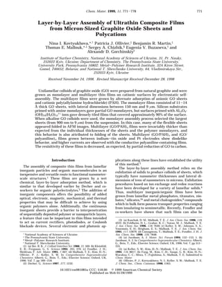
All GO devices tested in this manner showed rectify-
ing behavior (Figure 5). (An ITO/Pt control experiment
gave the expected ohmic response). For the 60-nm-thick
ITO-(GO/PAH)14GO-Pt device (curve 2), the “forward”
(ITO(-)/Pt(+)) and “reverse” bias turn-on potentials
were 0.42 and 0.82 V, respectively. These potentials
correspond to electric fields, E, of 7.0 × 10⁴ and 1.4 ×
105 V cm-1, respectively. When the conducting polymer
PAN is substituted for PAH (curve 1), the forward bias
turn-on potential is basically unaffected, but the reverse
bias turn-on potential decreases to 0.41 V. In this case
the electric fields required to obtain a current density
of 5 mA cm-2 were 4.8 and 4.4 × 10⁴ V cm-1 in the
forward and reverse directions, respectively. These
fields are 1-2 orders of magnitude smaller than those
of single and bilayer polymer devices.26 For both devices,
the current follows the ln(I) ∼ E-1 law, as expected for
a tunneling-based charge injection mechanism. This is
similar to the behavior observed for most single and
bilayer polymer diode devices.
The resistivity of both the ITO-(GO/PAH)14GO-Pt
and ITO-(GO)x-Pt devices is on the order of 106 Ω cm,
and that of the thicker ITO-(GO/PAN)30GO-Pt device
is approximately 1 order of magnitude lower. The
(26) (a) Greenham, N. C.; Moratti, S. C.; Bradley, D. D. C.; Friend,
R. H.; Holmes, A. B. Nature 1998, 365, 628. (b) Vestweber, H.; Oberski,
J.; Greiner, A.; Heitz, W.; Mahrt, R. F.; Baessler, H. Adv. Mater. Opt.
Electron. 1993, 2, 197.
Table 1. Characterization of Multilayer GO/PAH Films by AFM and Ellipsometry
sample
average roughness of the
anchored substrate surface, Å
average roughness of
the film surface, Å
total film
thickness, Å
average increase in film
thickness per PAH/GO
bilayer, Å
Si(NH2)/(GO/PAH)3GO 3.8 27 137 23 (first, second)
49 (third, fourth)
Si(NH2)/(GO/PAH)3GOa 3.8 13 105 29
Si(OH)/PAH/(GO/PAH)3GO 6.2 26 176 51
Si(OH)/Al-Kg/(GO/PAH)3GO 4.3 20 130 38
Glass/Al/Al2O3/(GO/PAH)4GO 35.0 22
Al foil/Al2O3/(GO/PAH)4GO 48.0 58
a GO was adsorbed from aqueous ammonia solution (pH 9).
Figure 5. Current vs voltage characteristics of GO colloid and
GO/polycation multilayer films deposited on ITO-coated
glass: (1) 120-nm-thick ITO-(GO/PAN)30GO-Pt device; (2) 60-
nm-thick ITO-(GO/PAH)14GO-Pt; (3) 90-nm-thick ITO-
(GO)x-Pt. The positive direction on the voltage axis is ITO(+)/
Pt(-).
Assembly of Ultrathin Composite Films Chem. Mater., Vol. 11, No. 3, 1999 777
8. difference arises from the electronic conductivity of the
PAN layers, which mediate electron transfer between
GO layers. For both the GO/polycation and GO films,
an irreversible conversion to a more conductive state
occurs when the device is held at high current density.
For ITO-(GO/PAH)14GO-Pt and ITO-(GO/PAN)30GO-
Pt, this effect became noticeable at current densities of
17 and 70mA/cm2, respectively. A similar effect begins
at a current density of about 40 mA/cm2 with ITO-
(GO)x-Pt. At current densities above 470 mA/cm2, the
current gradually increases by 3 orders of magnitude
at constant voltage with the ITO-(GO/PAN)30GO-Pt
device. We tentatively ascribe this behavior to an
internal electrochemical reaction, which reduces GO to
a more conductive carbon-rich material. Apparently, the
PAN samples are more resistant to this effect, possibly
because the PAN itself acts as a reservoir of oxidizing
equivalents. Similar electrochemical effects have been
found with electrodes prepared from bulk GO27 and
were also observed by Kotov et al., in their study of GO/
poly(diallyldimethylammonium chloride) thin films.7
Conclusions
We have shown that the quality and morphology of
GO monolayer thin films depend on the source of
graphite, its degree of oxidation, and the conditions used
to prepare the GO colloid, as well as on the nature of
the surface-priming layer and the pH of the adsorbing
solutions. By properly controlling these parameters, one
can select intact, unilamellar GO sheets and achieve
reasonably dense (ca. 90%) coverage on a cationic
surface. GO sheets prepared in this manner from
natural graphite have larger lateral dimensions (1-9
µm) than any other lamellar inorganic colloid studied
to date. The thickness of an individual GO layer, which
can be fully exfoliated by means of preoxidation and
oxidation steps, followed by appropriate dilution, is on
the order of 10-14 Å
Multilayer GO/PAH films deposited in four or five
adsorption cycles completely cover the surface of cationic
substrates. The average roughness of these multilayer
films is lowest when the GO suspension contains large
sheets and when the coverage of the first layer of sheets
is highest. However, sequential adsorption of GO and
polycations invariably results in an average thickness
change per adsorption cycle that is 2-3 times the
monolayer thickness. This appears to occur because the
flexible GO sheets fold and overlap on the surface.
The electronic characteristics of GO multilayer films
contacted by ITO and Pt electrodes are consistent
with its hole-conducting properties. By interleaving GO
with poly(aniline), a hole-conducting polymer, the di-
odelike behavior of the films is retained, but the
conductivity is increased by approximately 1 order of
magnitude. Thin film GO devices are, however, ir-
reversibly changed at high current density, most prob-
ably because of electrochemical reduction of GO to
carbon.
Acknowledgment. This work was supported by
Civilian Research and Development Foundation (UC1-
338), and by the National Science Foundation (CHE-
9529202). Instrumentation for AFM experiments was
provided by National Science Foundation grant CHE-
9626326.
CM981085U(27) Touzain, P.; Yazami, R. J. Power Sources 1985, 14, 99.
778 Chem. Mater., Vol. 11, No. 3, 1999 Kovtyukhova et al.