SlideShare a Scribd company logo
1 of 16
Download to read offline
MIDSHIP SECTION
M.R.
S.R.
A.P.
H.B.
H.B.
BOAT
LIFE H.B.
H.B.
F.M.
PROFILE
BOSUN STORE
BOSUN STORE
M S D
C.L C.C
P.P.F.
A.H
A.H
L.H. L.H.
M.H.
UP
L.H.
A.H
A.H
L.H.
A.H
L.H.
M.H.
FAINT
A.H DECK
STORE
LAMP RM. BOS'N STORE
C.L.
DN
A.H
A.H
L.H. L.H.
A.H
A.H
M.H.
L.H.
UP
C.L C.C
P.P.F.
FAN
ROOM
FAN
ROOM
NO
. 3
CARG
O
HATCH
NO
. 2
CARG
O
HATCH
NO
. 1
CARG
O
HATCH
NO. 2 T. S. T. (S)
NO. 1 T. S. T. (P)
NO. 2 T. S. T. (P)
NO. 1 T. S. T. (S)
PILOT LADD ACCOMM LADD
C C
C.C.
B.C
F.L.
UP.
P.C
PROT LADD
C.C C.L.
ACCOMM LADD
C.C.
TALLY
EMERGE
RM. STORE
CONTROL
ROOM M.H.
F.L
F.L
EL.
EL.
P.C.
R.M.
DN
DN
V.T.
WORK
SHOP
V.T.
DN
A.H.
L.H. L.H.
A.H.
UP
UP
STORE STORE
PROV. PROV.
LOBBY
HOSPITAL
REF. FISH MEAT
M. RM.
V.T
DN
V.T
STAT
FIRE
UP.
UP
GYM SPACE
A.H.
A.H.
L.M.
VEG.
HOSP.
W.C.
V.T.
DRY RM.
PIPE
S.P.
E.G.
C.
DECK
FAN RM.
R.H.
L.H. L.H.
A.H.
A.H.
L.H.
A.H.
A.H.
UP
M.H.
V.
C.L. C.C.
NO. 5 T. S. T. (P)
H.B.
ENGINE
OPEN
LO
O
P
BELT
CASING
O
PENING
VENT
O
PENING
VENT
O
PENING NO
. 6
CARG
O
HATCH
NO
. 5
CARG
O
HATCH
NO
. 4
CARG
O
HATCH
NO. 4 T. S. T. (S)
D.O. SERV.
PIPE
NO. 4 T. S. T. (P)
NO.7CARGO
HATCH
F.L.
P.C.
(VOID)
NO. 5 T. S. T. (P)
NO. 3 T. S. T. (P)
NO. 3 T. S. T. (S)
LENGTH
LENGTH
BREADTH
DEPTH
DRAFT
CLASS
SPEED TRIAL MAX
150M COASTAL TANKER
DEADWEIGHT
GROSS TONNAGE
NET TONNAGE
60939TON
37168
14828
20 knots
18 knots
PROPELLER SPECS
PRINCIPAL DIMENSIONS
(O.A.)
(B.P.)
(MLD.)
(MLD.)
(EXT.)
150 M
143 M
11.9 M
24 M
9.95 M
3RD DECK LOW. BRI DECK
D.
ENGINE
CONTROL RM.
U.
GALLEY
U.
D.
C. L.
A.P.
E.F.P.
RM.
10 15 20 25 30 35
C. L.
40
C. L.
10
D.
CREW'S
W.C.
V.T.
D.
U.
H.B.
SAIL
(D)
SAIL
(C)
SAIL SAIL CREW'S
(A) SHOW RM.(B)
D.
BOS'N
U
V.T.
O/M (A)
O/M (B)
O/M (C)
15 20
AIR COND.
RM.
LKR.
JUMP
25 30
V.T. D. V.T. V.T.
D.
U.
BATT.
RM.
OIL OIL OIL FITT.
CREW'S
CREW'S
SPARE
RM.
CARPENT
35
C. L.
40
SPARE
RM.
NO.1 OIL
ENGINEOPEN
H.B.H.B.
UPP.
A.P.T.(S.W
.)
ENG
INE
O
PEN
2ND DECK UPP. BRI DECK
WORK SHOP
STORE RM.
AUX. MACHINERY
ROOM
U
H.B.
U
U
C. L.
0 A.P.A.P.
RM.
5
STEER. GEAR
U
10 15 20 25 30 35 40 45 50
C.L.
10 15 20 25
U
D
D
V.C
D
W.C.
OFF.
U
30
DN.
D
U
D H.B.
U
D.
SPARE
SPARE
RM.
2/OFF.
F.H.
3/OFF.
C/OFF.
C/OFF.
BED
RM.
ELEC. EQUIPMENT
ROOM
C/OFF.
DAY RM.
UP V.T.
OFF'S
SHOW
V.T. RM.
35
LINEN
LKR.
3/ENG.
40
V.T.
D
DAY RM.
C/ENG.
C.L.
ELECT
ENG. P/O
1/ENG.
DAY
RM.
1/ENG.
RM.
BED
1/ENG.
LAV.
C/ENG
LAV.
C/ENG.
BED RM.
DRI W. T. (S)
NO. 2
F. W
. T. (P)
ENGINEO
PEN
LOOP
BELT
CASING
ENG
INE
O
PEN
NO.1F.W.T.(P)
NO.3D.O.T.(S)
WIND
D.
F.N.
C. L.
115 120 125 130 135
F.P
F.P. U.
140
R.M.
S.D.
145 150
C. L.
D.
WIND
F.L. F'CLE DECK
P.C.
F.L.
F.L.
F.L.
P.C.
F.L.
F.L.
B.L.
0 AP 10 15 20 25 30 35 40 45 50 55 60 65 70 75 80 85 90 95 100 105 110 115 120 130 135 140 FP 150125
TYPE
IMMERSION
DIAMETER
PITCH
EXP AREA RATIO
B-SERIES 3 BLADE
7.8 M
2.34 M
3.9 M
0.55 M
Tanks and Compartments
TANKS AND COMPARTMENTS
AP FP
Baseline
STR ER PUMPROOM
FOT 1 PS
FOT 1 SB
FOT 2 PS
FOT 2 SB
FWD COMP
BT PS (FWD)
BT SB (FWD)
SLOPCOMPSLOPTK
FWT PS (1)
FWT BS (1)
HOLD 1COT (1)
SD BT PS (1)
DB BT PS (1)
DB BT SB (1)
SD BT SB (1)
HOLD 2COT (2)
SD BT PS (2)
DB BT PS (2)
SD BT SB (2)
DB BT SB (2)
HOLD 3COT (3)
SD BT PS (3)
DB BT PS (3)
SD BT SB (3)
DB BT SB (3)
HOLD 4COT (4)
SD BT PS (4)
DB BT PS (4)
SD BT SB (4)
DB BT SB (4)
HOLD 5COT (5)
SD BT PS (5)
DB BT PS (5)
SD BT SB (5)
DB BT SB (5)
HOLD 6COT (6)
SD BT PS (6)
DB BT PS (6)
SD BT SB (6)
DB BT SB (6)
Zero pt.
AP FP
Baseline
STR
ER PUMPROOMFOT 1 PSFOT 1 SB
FOT 2 PSFOT 2 SB
FWD COMPBT PS (FWD)BT SB (FWD)SLOPCOMPSLOPTKFWT PS (1)FWT BS (1)HOLD 1COT (1)SD BT PS (1)
DB BT PS (1)DB BT SB (1)
SD BT SB (1) HOLD 2COT (2)SD BT PS (2)
DB BT PS (2)
SD BT SB (2)
DB BT SB (2)
HOLD 3COT (3)SD BT PS (3)
DB BT PS (3)
SD BT SB (3)
DB BT SB (3)
HOLD 4COT (4)SD BT PS (4)
DB BT PS (4)
SD BT SB (4)
DB BT SB (4)
HOLD 5COT (5)SD BT PS (5)
DB BT PS (5)
SD BT SB (5)
DB BT SB (5)
HOLD 6COT (6)SD BT PS (6)
DB BT PS (6)
SD BT SB (6)
DB BT SB (6)
Zero pt.
Tanks and Compartments
HULL STRUCTURE
SYSTEM HEAD HEAD LOSS CALCULATION PUMP SIZING
FITTING/VALVE CONDITION K FACTOR Subject Value Units
45° Elbow Standard radius 0.3 Total Volume Tank (ƩV) 16895.57 m
3
Standard radius 0.6 Discharge Time 4 hours 14400 (s) 4 x 3600
Long radius 0.3 Flow rate (Q) - For Ship 0.293 m
3
/s
Return Bend 0.8 Diameter 0.5 m
Socket or Coupler Screwed type 0.03 Velocity 1.494 m/s
Along line of flow 0.3 Area 0.196 m
2
Through side 0.8
Gate Valve Fully open 0.2 Dynamic Viscosity, ( µ ) 0.09 Pa. s
Fully open 6 Density, (ρ) 888.30 Kg/m
3
from Density Table
¾ open 8 Kinematic Viscosity (γ) 0.000004
½ open 12
¼ open 24 Re 186737.003
Hinged or swing disc 1.7 (10^6)/ Re 5.355
Ball or poppet type 4 Roughness Value ε 0.045 mm
Hinged or swing disc 3 Relative roughness εR 0.00009
Ball or poppet type 7
Contracting 0 (negligible) Laminar 0.000342728
Enlarging 0.75 Turbulent 0.005509531
Sudden contraction 0.25
Sudden enlargement 1 Length from shore 120 m
Tank to pipe line Sudden entrance 0.5 Head Static 30 m
Pipe line to tank Sudden exit 1 Total Head (ƩHT) 204682.849
Pipe line
γ = µ/ρ
Formula
Q/v
Hsystem= HfL+Hfv+Hfstatic
HfL = ﴾ f L/d ﴿ v
2
/2g
Hfv= ΣK.V
2
/2g
Hfstatic= Given in Question (30)
90° Elbow
Tee
Globe Valve
Check Valve
Foot Valve with strainer
Gradual transition
Head Loss Calculation Sheet
Not more than 2 m/s
CARGO PIPING SYSTEM MARINE SYSTEM DESIGN
SYSTEM HEAD HEAD LOSS CALCULATION PUMP SIZING
Volume m
3
1129.447
1129.447
1486.584
1486.583
1486.584
1486.584
1495.512
1495.512
1489.057
1489.058
1360.599
1360.599
16895.566
Crude Oil particular
9.8100 888.3000 0.0900 0.000004
LOA=
CARGO PUMP=
TYPE=
RPM=
HfL = ﴾ f L/d ﴿ v
2
/2g
Hfv= ΣK.V
2
/2g
Hfstatic= Given in Question (30)
Hsystem= HfL+Hfv+Hfstatic
Pump = Gravity.Density.(HfS + Hfstatic)
Cargo Oil Tank 4 (S)
Cargo Oil Tank 4 (P)
Cargo Oil Tank 5 (S)
Cargo Oil Tank 5 (P)
Total volume Tank
Kinematic
Viscosity, m2
/s
150M
4x PUMP
Split Casing Centrifugal Pumps
1480RPM
Dynamic Viscosity Pa.SDensityGravity
ITEM
Cargo Oil Tank 1 (S)
Cargo Oil Tank 1 (P)
Cargo Oil Tank 2 (P)
Cargo Oil Tank 2 (S)
Cargo Oil Tank 6 (S)
Cargo Oil Tank 6 (P)
General Particular
Cargo Oil Tank 3 (S)
Cargo Oil Tank 3 (P)
CARGO PIPING SYSTEM MARINE SYSTEM DESIGN
SYSTEM HEAD HEAD LOSS CALCULATION PUMP SIZING
HfS
Item Type of Fitting Qty K factor ΣK factor L HfL Hfv HfL+Hfv Hfstatic Head System Ppump(kPa)
1 sudden entrance 1 0.5 0.5
2 Gate Valve 2 0.2 0.4
3 Tee Along Line of Flow 1 0.3 0.3
4 90° Elbow Standard Radius 1 0.6 0.6
5 Main Pipeline 1.8 138.6 0.1737199 0.2047 0.378465 30 30.3785 264724.7214
Item Type of Fitting Qty K factor ΣK factor L HfL Hfv HfL+Hfv Hfstatic Head System Ppump(kPa)
1 sudden entrance 1 0.5 0.5
2 Gate Valve 2 0.2 0.4
3 90° Elbow Standard Radius 1 0.6 0.6
4 Main Pipeline 1.5 138.4 0.173469222 0.170621 0.34409 30 30.34409 264425.1707
Item Type of Fitting Qty K factor ΣK factor L HfL Hfv HfL+Hfv Hfstatic Head System Ppump(kPa)
1 sudden entrance 1 0.5 0.5
2 Gate Valve 2 0.2 0.4
3 Tee Along Line of Flow 2 0.3 0.6
4 90° Elbow Standard Radius 1 0.6 0.6
5 Main Pipeline 2.1 153.25 0.192082068 0.23887 0.430952 30 30.43095 265182.0997
Item Type of Fitting Qty K factor ΣK factor L HfL Hfv HfL+Hfv Hfstatic Head System Ppump(kPa)
1 sudden entrance 1 0.5 0.5 0
2 Gate Valve 3 0.2 0.6 0
3 90° Elbow Standard Radius 1 0.6 0.6 0
4 Main Pipeline 1.7 153.05 0.19183139 0.193371 0.385202 30 30.3852 264783.4269
Item Type of Fitting Qty K factor ΣK factor L HfL Hfv HfL+Hfv Hfstatic Head System Ppump(kPa)
1 sudden entrance 1 0.5 0.5
2 Gate Valve 3 0.2 0.6
3 Tee Along Line of Flow 3 0.3 0.9
4 90° Elbow Standard Radius 1 0.6 0.6
5 Main Pipeline 2.6 169.52 0.212474729 0.295743 0.508218 30 30.50822 265855.4163
CARGO TANK 3(S)
CARGO TANK 3(P)
CARGO TANK 1(S)
CARGO TANK 1(P)
CARGO TANK 2(S)
CARGO TANK 2(P)
CARGO PIPING SYSTEM MARINE SYSTEM DESIGN
SYSTEM HEAD HEAD LOSS CALCULATION PUMP SIZING
Item Type of Fitting Qty K factor ΣK factor L HfL Hfv HfL+Hfv Hfstatic Head System Ppump(kPa)
1 sudden entrance 1 0.5 0.5
2 Gate Valve 4 0.2 0.8
3 90° Elbow Standard Radius 1 0.6 0.6
4 Main Pipeline 1.9 169.3 0.212198983 0.21612 0.428319 30 30.42832 265159.1588
Item Type of Fitting Qty K factor ΣK factor L HfL Hfv HfL+Hfv Hfstatic Head System Ppump(kPa)
1 sudden entrance 1 0.5 0.5
2 Gate Valve 4 0.2 0.8
3 Tee Along Line of Flow 4 0.3 1.2
4 90° Elbow Standard Radius 1 0.6 0.6
5 Main Pipeline 3.1 185.73 0.232792186 0.352617 0.585409 30 30.58541 266528.0775
Item Type of Fitting Qty K factor ΣK factor L HfL Hfv HfL+Hfv Hfstatic Head System Ppump(kPa)
1 sudden entrance 1 0.5 0.5
2 Gate Valve 4 0.2 0.8
3 90° Elbow Standard Radius 1 0.6 0.6
4 Main Pipeline 1.9 185.51 0.23251644 0.21612 0.448637 30 30.44864 265336.2096
Item Type of Fitting Qty K factor ΣK factor L HfL Hfv HfL+Hfv Hfstatic Head System Ppump(kPa)
1 sudden entrance 1 0.5 0.5
2 Gate Valve 5 0.2 1
3 Tee Along Line of Flow 5 0.3 1.5
4 90° Elbow Standard Radius 1 0.6 0.6
5 Main Pipeline 3.6 202.42 0.253711271 0.409491 0.663202 30 30.6632 267205.9815
Item Type of Fitting Qty K factor ΣK factor L HfL Hfv HfL+Hfv Hfstatic Head System Ppump(kPa)
1 sudden entrance 1 0.5 0.5
2 Gate Valve 5 0.2 1
3 90° Elbow Standard Radius 1 0.6 0.6
4 Main Pipeline 2.1 202.2 0.253435525 0.23887 0.492305 30 30.49231 265716.7474
CARGO TANK 5(P)
CARGO TANK 4(S)
CARGO TANK 4(P)
CARGO TANK 5(S)
CARGO PIPING SYSTEM MARINE SYSTEM DESIGN
SYSTEM HEAD HEAD LOSS CALCULATION PUMP SIZING
Item Type of Fitting Qty K factor ΣK factor L HfL Hfv HfL+Hfv Hfstatic Head System Ppump(kPa)
1 sudden entrance 1 0.5 0.5
2 Gate Valve 5 0.2 1
3 Tee Along Line of Flow 6 0.3 1.8
4 90° Elbow Standard Radius 1 0.6 0.6
5 Main Pipeline 3.9 219.74 0.275419991 0.443615 0.719035 30 30.71904 267692.5224
Item Type of Fitting Qty K factor ΣK factor L HfL Hfv HfL+Hfv Hfstatic Head System Ppump(kPa)
1 sudden entrance 1 0.5 0.5
2 Gate Valve 5 0.2 1
3 90° Elbow Standard Radius 1 0.6 0.6
4 Main Pipeline 2.1 219.52 0.275144246 0.23887 0.514014 30 30.51401 265905.922
1 m 3.28084 ft Q = 0.2933 m3
/s Dia, (m)= 0.5 m
39.37008 inch 4649.2139 gpm 19.68503935 inch
1 m3
/s = 15850 gpm 4x Pumps 1162.303477 Area, (m
2
) 0.1963
1 Pumps= 3962.5
Item Q (Flow Rate)
H. loss
( pipe +fitting)
A A2
Q2
H.fluid H.static H.system Q (gpm) H.S (Feet)
1 0 0.7190 0.1963 0.0386 0.000 0 30 30 0 98.4252
2 0.15 0.7190 0.1963 0.0386 0.023 0.419636099 30 30.41964 594.375 99.80196
3 0.3 0.7190 0.1963 0.0386 0.090 1.678544394 30 31.67854 1188.75 103.9322
4 0.45 0.7190 0.1963 0.0386 0.203 3.776724887 30 33.77672 1783.125 110.816
5 0.6 0.7190 0.1963 0.0386 0.360 6.714177577 30 36.71418 2377.5 120.4533
6 0.75 0.7190 0.1963 0.0386 0.563 10.49090246 30 40.4909 2971.875 132.8442
7 0.9 0.7190 0.1963 0.0386 0.810 15.10689955 30 45.1069 3566.25 147.9885
8 1.05 0.7190 0.1963 0.0386 1.103 20.56216883 30 50.56217 4160.625 165.8864
9 1.2 0.7190 0.1963 0.0386 1.440 26.85671031 30 56.85671 4755 186.5378
10 1.35 0.7190 0.1963 0.0386 1.823 33.99052399 30 63.99052 5349.375 209.9427
H = 56.8567 m
186.5377695 ft
CARGO TANK 6(S)
CARGO TANK 6(P)
CARGO PIPING SYSTEM MARINE SYSTEM DESIGN
SYSTEM HEAD HEAD LOSS CALCULATION PUMP SIZING
Item Q (GPM) Q (m
3
/hr) Q (m
3
/s) H.system (m) Cargo Tank Cargo TankH. loss( pipe +fitting)
1 0.0 0 0 30.00 1 (S) 6(S) 0.7190
2 594.4 0 0.15 30.42 1 (P) 6(P) 0.5140
3 1188.8 0 0.3 31.68 2 (S)
4 1783.1 0 0.45 33.78 2 (P)
5 2377.5 0 0.6 36.71 3 (S)
6 2971.9 0 0.75 40.49 3 (P)
7 3566.3 0 0.9 45.11 4 (S)
8 4160.6 0 1.05 50.56 4 (P)
9 4755.0 0 1.2 56.86 5 (S)
10 5349.4 0 1.35 63.99 5 (P)
MAX 0.7190
0.4283
0.5854
0.4486
0.6632
0.4923
0.5082
H. loss( pipe +fitting)
0.3785
0.3441
0.4310
0.3852
0 0.15 0.3
0.45
0.6
0.75
0.9
1.05
1.2
1.35
0
50
100
150
200
250
0 1000 2000 3000 4000 5000 6000
SystemHead(Feet)
Flow Rate (gpm))
Head System
CARGO PIPING SYSTEM MARINE SYSTEM DESIGN
SYSTEM HEAD HEAD LOSS CALCULATION PUMP SIZING
1 m 3.28084 ft Dia, (m)= 0.5 m
39.37008 inch 19.68503935 inch
1 m3
/s = 15850 gpm Area, (m2
) 0.1963
Q = 0.2933 m3
/s H = 56.8567 m
4649.2139 gpm 186.5377695 ft
1056.129888 m3
/h
Qtotal= 18596.85563 gpm
4x pump= 4600 m3
/h
0
50
100
150
200
250
0 1000 2000 3000 4000 5000 6000
Old Flow Rate
4649.2139 gpm
System Head
109 ft
New Flow Rate
5000 gpm
Pump Efficiency = 83 %
CARGO PIPING SYSTEM MARINE SYSTEM DESIGN
SYSTEM HEAD HEAD LOSS CALCULATION PUMP SIZING
2) Actual discharge time Qnew= 20000 gpm H.pump= 186.5378
1.26183 m
3
/s 56.8567
Impeller size= 14 inch Power=
0.3556 m
ft 83.00%
T= 3.719371126 m
3) New flow rate is 1.261829653 m
3
/s 150.0000 hp
111.8549808 kW
hrs // 3 hours 43 minutes 54 seconds
Pump Efficiency =
PUMP SPECS
System Head
109 ft
Old Flow Rate
1056 m3/h
𝑇𝑖𝑚𝑒 =
𝑉𝑜𝑙𝑢𝑚𝑒
𝐹𝑙𝑜𝑤 𝑅𝑎𝑡𝑒 (𝑛𝑒𝑤)
𝐹𝑙𝑜𝑤 𝑅𝑎𝑡𝑒 (𝑛𝑒𝑤) =
𝑉𝑜𝑙𝑢𝑚𝑒
𝑇𝑖𝑚𝑒
CARGO PIPING SYSTEM MARINE SYSTEM DESIGN
B.L.
0 AP 10 15 20 25 30 35 40 45 50 55 60 65 70 75 80 85 90 95 100 105 110 115 120 130 135 140 FP 150125
M.R.
S.R.
H.B.
H
1 2 3
G
F
E
4 5 6 7
D
C
B
A
31 2 54 876
Title/Name, designation, material, dimension etc
Checked by
10 11 12
Designed by
Itemref
13
Quantity
FilenameApproved by - date
14 15
Article No./Reference
Date
16
Edition Sheet
Scale
H
G
F
E
11109 1312
RevNo Revision note
D
C
B
Checked
15 1614
Date Signature
A
EN, HAMDAN
PIPING DESIGN
NAIM, JAMAL,IZWAFI XXX
MSD PROJECT 2
XXX - 10/4/2019
GROUP 2
10/4/19
L01 1/1
1:400
VENTILATION SYSTEM
Ventilation
ρw 1000 kg/m3
ε (mm) = 0.15 γ = 0.00005
ρa
1.099 kg/m3 εR =
# Item Type of Fitting Qty K factor ΣK factor ε (mm) Re Lcompt Volume (m3) ACHr Q (m3/s) Φ (m) Area m2
vel. m/s εR fturbulant 2f.L/D
1 Bend 0 0.75 0
2 Exit Flap 1 0.65 0.65
3
Volume
Control
1 0.65 0.65
Duct 1.3 0.15
964637.6857
24.6
4545.748
15 18.94061667 0.5 0.196349541 96.46376857 0.0006 0.018444485
1.814937356 0.158763372
# Item Type of Fitting Qty K factor ΣK factor ε (mm) Re Lcompt Volume (m3) ACHr Q (m3/s) Φ (m) Area m2
vel. m/s εR fturbulant 2f.L/D
1 Bend 2 0.75 1.5
2 Exit Flap 1 0.65 0.65
3
Volume
Control
Damper
0 0.65 0
4 Concentric reducer 2 0.8 1.6
Duct 3.75 0.15 742028.989 24.6 4545.748 15 18.94061667 0.65 0.331830724 57.079153 0.000461538 0.017573588 1.330185461 0.258928923
# Item Type of Fitting Qty K factor ΣK factor ε (mm) Re Lcompt Volume (m3) ACHr Q (m3/s) Φ (m) Area m2
vel. m/s εR fturbulant 2f.L/D
1 90 degree Bend 6 0.75 4.5
2 Exit Flap 1 0.75 0.75
3 Inlet grill and cowling 2 1 2
4 fire damper 1 0.6 0.6
5 expansion joint 4 0.65 2.6
6 Concentric reducer 2 0.8 1.6
7 Wye 0 0.09 0
8 damper gate round 1 0.045 0.045
Duct 12.095 0.15 1205797.107 50 56.82185 1.2 1.130973355 50.24154613 0.00025 0.015398487 1.283207269 0.681865814
Section1Section2Section3MainDuct
(2f.L/D + ΣK)/2g
(2f.L/D + ΣK)/2g
(2f.L/D + ΣK)/2g
(2f.L/D + ΣK)/2g
2
4
( )
2
air
water
FLV
StaticHeadLoss metres
gd
r
r
=
2
( )
2
air
water
V
VelocityHeadLoss k metres
g
r
r
=
VENTILATION SYSTEM DESIGN
VENTILATION SYSTEM
# Q Q2
Area2
(m4
) Hsystem PL (Pa)
1 0 0 1.2791 0.00 0
2 1 1 1.2791 0.0012 11.4503154
3 2 4 1.2791 0.0047 45.8012616
4 3 9 1.2791 0.0105 103.0528386
5 4 16 1.2791 0.0187 183.2050464
6 5 25 1.2791 0.0292 286.257885
7 6 36 1.2791 0.001493 0.0420 412.2113544
8 7 49 1.2791 0.001493 0.0572 561.0654547
9 8 64 1.2791 0.001493 0.0747 732.8201857
10 9 81 1.2791 0.001493 0.0945 927.4755475
11 10 100 1.2791 0.001493 0.1167 1145.03154
12 11 121 1.2791 0.001493 0.1412 1385.488164
PARAMETERS VALUE UNITS
Engine Power @ 18knt
MTU 8000kW
8000 kW
η 98.20% %
H 160 kW
ρ air 1.099 kg/m3
ρ water 1000 kg/m3
Cp 0.017 kW.min/kg.degC
ΔT 12 ᵒC
Volume Engine Room 4545.748 m3
Combustion Air 0.107
m3/min/brake
KW
Routing Factor 2.5 F
Ventilation Air Flow 1784.420652 m3/min H/D*Cp*ΔT 713.6612607
H= P*(1-EFF)
160
Parameters Value Units
Ventilation Air Required 1784.420652 m3/min
Flow Rate 18.94061667 m³/s
Velocity 96.46376857 m/s
Diameter² 0.25 m2
Diameter 0.5 m
Area 0.196349541 m²
Kinematic Viscosity 0.00001606
Reynolds Numbers 964637.6857
F Laminar
Absolute Roughness 0.15 m
Relative Roughness εR 0.0006 m
F Turbulence 0.018444485
0.001492977
Σ(2f.L/D + ΣK)ρa/2g/ρw
0.001492977
0.001492977
0.001492977
0.001492977
0.001492977
0
0.5
1
1.5
2
2.5
3
0 2 4 6 8 10 12
HSYSTEM
HSYSTEM
Hsystem
(m)
Q (m3/s)
Pascalsg
g
vk
g
vk
g
vk
dg
vLf
P w
w
ann
w
a
L 











 




))
2
....
22
((
2
4
(
22
22
2
11
2
VENTILATION SYSTEM DESIGN
M.R.
S.R.
H.B.
0 AP 10 15 20 25 30 35
U
C. L.
0 10 15 20 25 30 35 40 45 50
U
D
DN.
UP
DRI W. T. (S)
NO. 2
F. W
. T. (P)
LOOP
BELT
CASING
NO.1F.W.T.(P)
NO.3D.O.T.(S)
Date: 30/5/2019
Network 50Hz 415V 3 Phase 4-Wire System CABLING AND POWERING AWG STANDARD/IEC STANDARD
AC / DC
Diversity
Factor
Diversifie
d (kW)
Voltage (V) Current
(A)
Diversi
ty
Factor
Diversified
(kW)
Voltage (V) Current (A) Diversity
Factor
Diversified
(kW)
Voltage (V) Current
(A)
Cable
Size
(mm
2
)
AWG
1 Bilge/ Ballast Pump 2 5.5 11 AC 3 0.8 8.8 440 20.00 0.8 8.8 440 20.00 0.8 8.8 440 20.00 2.5 13
2 General Service/Fire Pump 2 5.5 11 AC 3 0.8 8.8 440 20.00 0.8 8.8 440 20.00 0.8 8.8 440 20.00 1.5 15
3 Engine Room Blower Fan No.1 - Port1 4 4 AC 3 1 4 400 10.00 1 4 400 10.00 1 4 400 10.00 4 11
4 Engine Room Blower Fan No.1 - Stbd1 4 4 AC 3 1 4 400 10.00 1 4 400 10.00 1 4 400 10.00 4 11
5 Sewage Pump 2 1.4 2.8 AC 3 1 2.8 440 6.36 1 2.8 440 6.36 1 2.8 440 6.36 1.5 15
6 Sea Water Pump (Domestic) 2 4 8 AC 3 0.5 4 440 9.09 0.5 4 440 9.09 0.5 4 440 9.09 1.5 15
7 Fuel Oil Transfer Pump 2 2.238 4.476 AC 3 0.7 3.1332 440 7.12 1 4.476 440 10.17 0.7 3.1332 440 7.12 1.5 15
8 Fresh Water Pump 2 2.2 4.4 AC 3 0.5 2.2 440 5.00 0.5 2.2 440 5.00 0.5 2.2 440 5.00 1.5 15
9 Oil Bilge Separator 1 0.4 0.4 AC 1 0.8 0.32 120 2.67 0 0 0 0.00 0.8 0.32 120 2.67 1.5 15
10 Steering Gear 1 2.5 2.5 AC 3 0.8 2 400 5.00 0 0 0 0.00 0.8 2 400 5.00 16 5
11 Winch & Power Pack 2 10 20 AC 3 0.8 16 440 36.36 0.8 16 440 36.36 0.8 16 440 36.36 6 9
12 Floor Standing Air-Con (Air-Con Plant)4 33.25 133 AC 3 1 133 400 332.50 1 133 400 332.50 1 133 400 332.50 1.5 15
13 Battery Charger 2 0.72 1.44 DC 1 0.25 0.36 120 3.00 0 0 0 0.00 0.25 0.36 120 3.00 1 15
14 Navigation Light Panel 2 0.25 0.5 AC 1 1 0.5 120 4.17 1 0.5 120 4.17 1 0.5 120 4.17 1 17
15 Radio Battery Charger 2 0.72 1.44 DC 1 0.25 0.36 120 3.00 0.25 0.36 120 3.00 0.25 0.36 120 3.00 1 17
16 Emergency Battery Charger 4 0.72 2.88 DC 1 0.5 1.44 120 12.00 0.5 1.44 120 12.00 0.5 1.44 120 12.00 1.5 15
17 Lighting 22 0.02 0.8 AC 1 1 0.8 120 6.67 1 0.8 120 6.67 1 0.8 120 6.67 1.5 15
18 Socket Outlet 110 0.02 2.2 AC 1 0.5 1.1 120 9.17 0.5 1.1 120 9.17 0.5 1.1 120 9.17 1 17
19 Toilet/Bath Room Fan 2 0.2 0.4 AC 1 1 0.4 120 3.33 1 0.4 120 3.33 1 0.4 120 3.33 1.5 15
20 Galley Fan 2 0.75 1.5 AC 1 0.4 0.6 120 5.00 0.4 0.6 120 5.00 0.4 0.6 120 5.00 1.5 15
21 Searchlight 4 1 4 AC 1 0.8 3.2 120 26.67 1 4 120 33.33 1 4 120 33.33 2.5 13
22 Floodlight 8 0.5 4 DC 1 0.6 2.4 120 20.00 1 4 120 33.33 1 4 120 33.33 2.5 13
23 Water Heater Bath Room 4 3.72 14.88 DC 1 0.5 7.44 240 31.00 0.5 7.44 240 31.00 0.5 7.44 240 31.00 1.5 15
24 Crane 1 600 600 AC 3 0.8 480 280 1714.29 0.9 540 280 1928.57 1 600 280 2142.86 25 3
25 Ship Whistle 1 1 1 DC 1 0.1 0.1 120 0.83 0 0 0 0.00 0.1 0.1 120 0.83 1 17
26 Hot Plate 1 3.5 3.5 AC 1 0.9 3.15 240 13.13 0 0 0 0.00 0.9 3.15 240 13.13 2.5 13
27 Rice Cooker 4 1.5 6 DC 1 1 6 240 25.00 0 0 0 0.00 1 6 240 25.00 1 17
28 Galley Freezer 2 1.5 3 AC 1 1 3 240 12.50 1 3 240 12.50 1 3 240 12.50 2.5 13
29 Fire Alarm System 4 0.25 1 DC 1 1 1 120 8.33 1 1 120 8.33 1 1 120 8.33 2.5 17
30 Steering Gear Ventilation Fan 1 4 4 DC 1 1 4 240 16.67 1 4 240 16.67 1 4 240 16.67 4 11
31 Radio communication 3 0.25 0.75 AC 1 0.25 0.1875 120 1.56 0.19 0.1425 120 1.19 0.25 0.1875 120 1.56 1.5 15
32 Refrigerator Compressor 2 3 6 DC 1 1 6 240 25.00 0 0 0 0.00 1 6 240 25.00 1.5 15
33 Cargo Oil Pump 4 112 448 AC 3 0.8 358.4 440 814.55 0 0 0 0.00 0.8 358.4 440 814.55 17
Installed
(kW)
1312.866
65.643
1378.509
(%)
35.555 37.843 41.675
746.645 794.701 875.165
PieceLoad Description
Item
No.
Max Demand
(at Sea)
(kW)
Max Demand
(Harbour)
(kW)
Normal at Sea Harbour Condition
Consumption
Total (kW)
Phase
Consumption
Single (kW)
711.091 756.859
Operation Condition
Max Demand
(Operation) (kW)
833.491Summary
Design Margin (5%)
Total
1 Generator 60 kW 1458.61324.51244.4
Page 1 of 1

More Related Content

What's hot

95 john paul mello - 7237539 - control method and apparatus for use in an a...
95   john paul mello - 7237539 - control method and apparatus for use in an a...95   john paul mello - 7237539 - control method and apparatus for use in an a...
95 john paul mello - 7237539 - control method and apparatus for use in an a...Mello_Patent_Registry
 
0.1-Overview-AZ-SA
0.1-Overview-AZ-SA0.1-Overview-AZ-SA
0.1-Overview-AZ-SANolan Chetty
 
10-13041-A3-U08-R03-P&ID FOR UTILITIES LINE
10-13041-A3-U08-R03-P&ID FOR UTILITIES LINE10-13041-A3-U08-R03-P&ID FOR UTILITIES LINE
10-13041-A3-U08-R03-P&ID FOR UTILITIES LINEShafairan Ramly
 
Patrones de descarga rociadores tfp710 10-2014
Patrones de descarga rociadores   tfp710 10-2014Patrones de descarga rociadores   tfp710 10-2014
Patrones de descarga rociadores tfp710 10-2014CARLOS GUANANGA
 
MV 600 SS SP vapaorizer (cyroquip)
MV 600 SS SP vapaorizer (cyroquip)MV 600 SS SP vapaorizer (cyroquip)
MV 600 SS SP vapaorizer (cyroquip)Adrian Mah Siew Hoe
 
ADVISORY SPARE-TPP.pdf
ADVISORY SPARE-TPP.pdfADVISORY SPARE-TPP.pdf
ADVISORY SPARE-TPP.pdfssuser62a594
 
Parker valve brochure
Parker valve brochure Parker valve brochure
Parker valve brochure ERIKS UK
 
Angel type control valve(2by2 way)
Angel type control valve(2by2 way)Angel type control valve(2by2 way)
Angel type control valve(2by2 way)amitkahire
 

What's hot (20)

Nlc co y-na60_02
Nlc co y-na60_02Nlc co y-na60_02
Nlc co y-na60_02
 
Compact Clean Steam Generator
Compact Clean Steam GeneratorCompact Clean Steam Generator
Compact Clean Steam Generator
 
Technical Information for PC4000 Pipeline Connector
Technical Information for PC4000 Pipeline ConnectorTechnical Information for PC4000 Pipeline Connector
Technical Information for PC4000 Pipeline Connector
 
Section02 check valves
Section02 check valvesSection02 check valves
Section02 check valves
 
LVF Stock List
LVF Stock ListLVF Stock List
LVF Stock List
 
Downpipe Liquid Level Sensor Purge Control
Downpipe Liquid Level Sensor Purge ControlDownpipe Liquid Level Sensor Purge Control
Downpipe Liquid Level Sensor Purge Control
 
LR- 0000012.PDF
LR- 0000012.PDFLR- 0000012.PDF
LR- 0000012.PDF
 
95 john paul mello - 7237539 - control method and apparatus for use in an a...
95   john paul mello - 7237539 - control method and apparatus for use in an a...95   john paul mello - 7237539 - control method and apparatus for use in an a...
95 john paul mello - 7237539 - control method and apparatus for use in an a...
 
Back pressure valves for industrial process control
Back pressure valves for industrial process controlBack pressure valves for industrial process control
Back pressure valves for industrial process control
 
Pressure regulator valves for industrial process control
Pressure regulator valves for industrial process controlPressure regulator valves for industrial process control
Pressure regulator valves for industrial process control
 
0.1-Overview-AZ-SA
0.1-Overview-AZ-SA0.1-Overview-AZ-SA
0.1-Overview-AZ-SA
 
10-13041-A3-U08-R03-P&ID FOR UTILITIES LINE
10-13041-A3-U08-R03-P&ID FOR UTILITIES LINE10-13041-A3-U08-R03-P&ID FOR UTILITIES LINE
10-13041-A3-U08-R03-P&ID FOR UTILITIES LINE
 
Patrones de descarga rociadores tfp710 10-2014
Patrones de descarga rociadores   tfp710 10-2014Patrones de descarga rociadores   tfp710 10-2014
Patrones de descarga rociadores tfp710 10-2014
 
MV 600 SS SP vapaorizer (cyroquip)
MV 600 SS SP vapaorizer (cyroquip)MV 600 SS SP vapaorizer (cyroquip)
MV 600 SS SP vapaorizer (cyroquip)
 
ADVISORY SPARE-TPP.pdf
ADVISORY SPARE-TPP.pdfADVISORY SPARE-TPP.pdf
ADVISORY SPARE-TPP.pdf
 
Vpa4000
  Vpa4000  Vpa4000
Vpa4000
 
854 f wiring
854 f wiring854 f wiring
854 f wiring
 
TrimTeck OpGL Control Valves
TrimTeck OpGL Control ValvesTrimTeck OpGL Control Valves
TrimTeck OpGL Control Valves
 
Parker valve brochure
Parker valve brochure Parker valve brochure
Parker valve brochure
 
Angel type control valve(2by2 way)
Angel type control valve(2by2 way)Angel type control valve(2by2 way)
Angel type control valve(2by2 way)
 

Similar to Marine System Design

DUG 2010 Technical Workshop Presentation
DUG 2010 Technical Workshop PresentationDUG 2010 Technical Workshop Presentation
DUG 2010 Technical Workshop PresentationHarbisonFischer
 
Plug Valve Installation and Operating Instructions
Plug Valve Installation and Operating InstructionsPlug Valve Installation and Operating Instructions
Plug Valve Installation and Operating Instructionsalexbrown529
 
Thomson Linear RoundRail 1CC Specs
Thomson Linear RoundRail 1CC SpecsThomson Linear RoundRail 1CC Specs
Thomson Linear RoundRail 1CC SpecsElectromate
 
Thomson roundrail 1_cc_specsheet
Thomson roundrail 1_cc_specsheetThomson roundrail 1_cc_specsheet
Thomson roundrail 1_cc_specsheetElectromate
 
2018 pumster english catalog
2018 pumster english catalog2018 pumster english catalog
2018 pumster english catalogpumster
 
Bombas de Refrigeração Hermetic
Bombas de Refrigeração HermeticBombas de Refrigeração Hermetic
Bombas de Refrigeração HermeticVibropac
 
Hyster k007 (h9 xm 6 europe) forklift service repair manual
Hyster k007 (h9 xm 6 europe) forklift service repair manualHyster k007 (h9 xm 6 europe) forklift service repair manual
Hyster k007 (h9 xm 6 europe) forklift service repair manualifjkdkkmmms
 
Hyster k007 (h8 xm 6 europe) forklift service repair manual
Hyster k007 (h8 xm 6 europe) forklift service repair manualHyster k007 (h8 xm 6 europe) forklift service repair manual
Hyster k007 (h8 xm 6 europe) forklift service repair manualfujsefkskemm
 
Hyster k007 (h12 xm 6 europe) forklift service repair manual
Hyster k007 (h12 xm 6 europe) forklift service repair manualHyster k007 (h12 xm 6 europe) forklift service repair manual
Hyster k007 (h12 xm 6 europe) forklift service repair manualfujsefkskemm
 
Hyster k007 (h12 xm 6 europe) forklift service repair manual
Hyster k007 (h12 xm 6 europe) forklift service repair manualHyster k007 (h12 xm 6 europe) forklift service repair manual
Hyster k007 (h12 xm 6 europe) forklift service repair manualhhjsekmdmm
 
Hyster k007 (h9 xm 6 europe) forklift service repair manual
Hyster k007 (h9 xm 6 europe) forklift service repair manualHyster k007 (h9 xm 6 europe) forklift service repair manual
Hyster k007 (h9 xm 6 europe) forklift service repair manualhhjsekmdmm
 
Hyster k007 (h12 xm 6 europe) forklift service repair manual
Hyster k007 (h12 xm 6 europe) forklift service repair manualHyster k007 (h12 xm 6 europe) forklift service repair manual
Hyster k007 (h12 xm 6 europe) forklift service repair manualifjkdkkmmms
 
Hyster k007 (h10 xm 6 europe) forklift service repair manual
Hyster k007 (h10 xm 6 europe) forklift service repair manualHyster k007 (h10 xm 6 europe) forklift service repair manual
Hyster k007 (h10 xm 6 europe) forklift service repair manualfujsefkskemm
 
Hyster k007 (h8 xm 6 europe) forklift service repair manual
Hyster k007 (h8 xm 6 europe) forklift service repair manualHyster k007 (h8 xm 6 europe) forklift service repair manual
Hyster k007 (h8 xm 6 europe) forklift service repair manualifjkdkkmmms
 
Hyster k007 (h9 xm 6 europe) forklift service repair manual
Hyster k007 (h9 xm 6 europe) forklift service repair manualHyster k007 (h9 xm 6 europe) forklift service repair manual
Hyster k007 (h9 xm 6 europe) forklift service repair manualfujsefkskemm
 

Similar to Marine System Design (20)

Catalogo neumatic
Catalogo neumaticCatalogo neumatic
Catalogo neumatic
 
Trunnion Mount Ball Valves For Industrial Pipelines
Trunnion Mount Ball Valves For Industrial PipelinesTrunnion Mount Ball Valves For Industrial Pipelines
Trunnion Mount Ball Valves For Industrial Pipelines
 
Control Valves (THINKTANK®️)
Control Valves (THINKTANK®️)Control Valves (THINKTANK®️)
Control Valves (THINKTANK®️)
 
Estimated Civil & Structural Quantities
Estimated Civil & Structural QuantitiesEstimated Civil & Structural Quantities
Estimated Civil & Structural Quantities
 
DUG 2010 Technical Workshop Presentation
DUG 2010 Technical Workshop PresentationDUG 2010 Technical Workshop Presentation
DUG 2010 Technical Workshop Presentation
 
Plug Valve Installation and Operating Instructions
Plug Valve Installation and Operating InstructionsPlug Valve Installation and Operating Instructions
Plug Valve Installation and Operating Instructions
 
Thomson Linear RoundRail 1CC Specs
Thomson Linear RoundRail 1CC SpecsThomson Linear RoundRail 1CC Specs
Thomson Linear RoundRail 1CC Specs
 
Thomson roundrail 1_cc_specsheet
Thomson roundrail 1_cc_specsheetThomson roundrail 1_cc_specsheet
Thomson roundrail 1_cc_specsheet
 
2018 pumster english catalog
2018 pumster english catalog2018 pumster english catalog
2018 pumster english catalog
 
Water flow pipe sizes
Water flow pipe sizesWater flow pipe sizes
Water flow pipe sizes
 
Bombas de Refrigeração Hermetic
Bombas de Refrigeração HermeticBombas de Refrigeração Hermetic
Bombas de Refrigeração Hermetic
 
Hyster k007 (h9 xm 6 europe) forklift service repair manual
Hyster k007 (h9 xm 6 europe) forklift service repair manualHyster k007 (h9 xm 6 europe) forklift service repair manual
Hyster k007 (h9 xm 6 europe) forklift service repair manual
 
Hyster k007 (h8 xm 6 europe) forklift service repair manual
Hyster k007 (h8 xm 6 europe) forklift service repair manualHyster k007 (h8 xm 6 europe) forklift service repair manual
Hyster k007 (h8 xm 6 europe) forklift service repair manual
 
Hyster k007 (h12 xm 6 europe) forklift service repair manual
Hyster k007 (h12 xm 6 europe) forklift service repair manualHyster k007 (h12 xm 6 europe) forklift service repair manual
Hyster k007 (h12 xm 6 europe) forklift service repair manual
 
Hyster k007 (h12 xm 6 europe) forklift service repair manual
Hyster k007 (h12 xm 6 europe) forklift service repair manualHyster k007 (h12 xm 6 europe) forklift service repair manual
Hyster k007 (h12 xm 6 europe) forklift service repair manual
 
Hyster k007 (h9 xm 6 europe) forklift service repair manual
Hyster k007 (h9 xm 6 europe) forklift service repair manualHyster k007 (h9 xm 6 europe) forklift service repair manual
Hyster k007 (h9 xm 6 europe) forklift service repair manual
 
Hyster k007 (h12 xm 6 europe) forklift service repair manual
Hyster k007 (h12 xm 6 europe) forklift service repair manualHyster k007 (h12 xm 6 europe) forklift service repair manual
Hyster k007 (h12 xm 6 europe) forklift service repair manual
 
Hyster k007 (h10 xm 6 europe) forklift service repair manual
Hyster k007 (h10 xm 6 europe) forklift service repair manualHyster k007 (h10 xm 6 europe) forklift service repair manual
Hyster k007 (h10 xm 6 europe) forklift service repair manual
 
Hyster k007 (h8 xm 6 europe) forklift service repair manual
Hyster k007 (h8 xm 6 europe) forklift service repair manualHyster k007 (h8 xm 6 europe) forklift service repair manual
Hyster k007 (h8 xm 6 europe) forklift service repair manual
 
Hyster k007 (h9 xm 6 europe) forklift service repair manual
Hyster k007 (h9 xm 6 europe) forklift service repair manualHyster k007 (h9 xm 6 europe) forklift service repair manual
Hyster k007 (h9 xm 6 europe) forklift service repair manual
 

Recently uploaded

Porous Ceramics seminar and technical writing
Porous Ceramics seminar and technical writingPorous Ceramics seminar and technical writing
Porous Ceramics seminar and technical writingrakeshbaidya232001
 
(PRIYA) Rajgurunagar Call Girls Just Call 7001035870 [ Cash on Delivery ] Pun...
(PRIYA) Rajgurunagar Call Girls Just Call 7001035870 [ Cash on Delivery ] Pun...(PRIYA) Rajgurunagar Call Girls Just Call 7001035870 [ Cash on Delivery ] Pun...
(PRIYA) Rajgurunagar Call Girls Just Call 7001035870 [ Cash on Delivery ] Pun...ranjana rawat
 
Coefficient of Thermal Expansion and their Importance.pptx
Coefficient of Thermal Expansion and their Importance.pptxCoefficient of Thermal Expansion and their Importance.pptx
Coefficient of Thermal Expansion and their Importance.pptxAsutosh Ranjan
 
APPLICATIONS-AC/DC DRIVES-OPERATING CHARACTERISTICS
APPLICATIONS-AC/DC DRIVES-OPERATING CHARACTERISTICSAPPLICATIONS-AC/DC DRIVES-OPERATING CHARACTERISTICS
APPLICATIONS-AC/DC DRIVES-OPERATING CHARACTERISTICSKurinjimalarL3
 
Call Girls in Nagpur Suman Call 7001035870 Meet With Nagpur Escorts
Call Girls in Nagpur Suman Call 7001035870 Meet With Nagpur EscortsCall Girls in Nagpur Suman Call 7001035870 Meet With Nagpur Escorts
Call Girls in Nagpur Suman Call 7001035870 Meet With Nagpur EscortsCall Girls in Nagpur High Profile
 
(SHREYA) Chakan Call Girls Just Call 7001035870 [ Cash on Delivery ] Pune Esc...
(SHREYA) Chakan Call Girls Just Call 7001035870 [ Cash on Delivery ] Pune Esc...(SHREYA) Chakan Call Girls Just Call 7001035870 [ Cash on Delivery ] Pune Esc...
(SHREYA) Chakan Call Girls Just Call 7001035870 [ Cash on Delivery ] Pune Esc...ranjana rawat
 
(ANJALI) Dange Chowk Call Girls Just Call 7001035870 [ Cash on Delivery ] Pun...
(ANJALI) Dange Chowk Call Girls Just Call 7001035870 [ Cash on Delivery ] Pun...(ANJALI) Dange Chowk Call Girls Just Call 7001035870 [ Cash on Delivery ] Pun...
(ANJALI) Dange Chowk Call Girls Just Call 7001035870 [ Cash on Delivery ] Pun...ranjana rawat
 
What are the advantages and disadvantages of membrane structures.pptx
What are the advantages and disadvantages of membrane structures.pptxWhat are the advantages and disadvantages of membrane structures.pptx
What are the advantages and disadvantages of membrane structures.pptxwendy cai
 
Introduction to IEEE STANDARDS and its different types.pptx
Introduction to IEEE STANDARDS and its different types.pptxIntroduction to IEEE STANDARDS and its different types.pptx
Introduction to IEEE STANDARDS and its different types.pptxupamatechverse
 
(MEERA) Dapodi Call Girls Just Call 7001035870 [ Cash on Delivery ] Pune Escorts
(MEERA) Dapodi Call Girls Just Call 7001035870 [ Cash on Delivery ] Pune Escorts(MEERA) Dapodi Call Girls Just Call 7001035870 [ Cash on Delivery ] Pune Escorts
(MEERA) Dapodi Call Girls Just Call 7001035870 [ Cash on Delivery ] Pune Escortsranjana rawat
 
Analog to Digital and Digital to Analog Converter
Analog to Digital and Digital to Analog ConverterAnalog to Digital and Digital to Analog Converter
Analog to Digital and Digital to Analog ConverterAbhinavSharma374939
 
chaitra-1.pptx fake news detection using machine learning
chaitra-1.pptx  fake news detection using machine learningchaitra-1.pptx  fake news detection using machine learning
chaitra-1.pptx fake news detection using machine learningmisbanausheenparvam
 
Software Development Life Cycle By Team Orange (Dept. of Pharmacy)
Software Development Life Cycle By  Team Orange (Dept. of Pharmacy)Software Development Life Cycle By  Team Orange (Dept. of Pharmacy)
Software Development Life Cycle By Team Orange (Dept. of Pharmacy)Suman Mia
 
Call for Papers - African Journal of Biological Sciences, E-ISSN: 2663-2187, ...
Call for Papers - African Journal of Biological Sciences, E-ISSN: 2663-2187, ...Call for Papers - African Journal of Biological Sciences, E-ISSN: 2663-2187, ...
Call for Papers - African Journal of Biological Sciences, E-ISSN: 2663-2187, ...Christo Ananth
 
Call Girls Service Nagpur Tanvi Call 7001035870 Meet With Nagpur Escorts
Call Girls Service Nagpur Tanvi Call 7001035870 Meet With Nagpur EscortsCall Girls Service Nagpur Tanvi Call 7001035870 Meet With Nagpur Escorts
Call Girls Service Nagpur Tanvi Call 7001035870 Meet With Nagpur EscortsCall Girls in Nagpur High Profile
 
HARMONY IN THE NATURE AND EXISTENCE - Unit-IV
HARMONY IN THE NATURE AND EXISTENCE - Unit-IVHARMONY IN THE NATURE AND EXISTENCE - Unit-IV
HARMONY IN THE NATURE AND EXISTENCE - Unit-IVRajaP95
 
(RIA) Call Girls Bhosari ( 7001035870 ) HI-Fi Pune Escorts Service
(RIA) Call Girls Bhosari ( 7001035870 ) HI-Fi Pune Escorts Service(RIA) Call Girls Bhosari ( 7001035870 ) HI-Fi Pune Escorts Service
(RIA) Call Girls Bhosari ( 7001035870 ) HI-Fi Pune Escorts Serviceranjana rawat
 
Processing & Properties of Floor and Wall Tiles.pptx
Processing & Properties of Floor and Wall Tiles.pptxProcessing & Properties of Floor and Wall Tiles.pptx
Processing & Properties of Floor and Wall Tiles.pptxpranjaldaimarysona
 

Recently uploaded (20)

Porous Ceramics seminar and technical writing
Porous Ceramics seminar and technical writingPorous Ceramics seminar and technical writing
Porous Ceramics seminar and technical writing
 
(PRIYA) Rajgurunagar Call Girls Just Call 7001035870 [ Cash on Delivery ] Pun...
(PRIYA) Rajgurunagar Call Girls Just Call 7001035870 [ Cash on Delivery ] Pun...(PRIYA) Rajgurunagar Call Girls Just Call 7001035870 [ Cash on Delivery ] Pun...
(PRIYA) Rajgurunagar Call Girls Just Call 7001035870 [ Cash on Delivery ] Pun...
 
Coefficient of Thermal Expansion and their Importance.pptx
Coefficient of Thermal Expansion and their Importance.pptxCoefficient of Thermal Expansion and their Importance.pptx
Coefficient of Thermal Expansion and their Importance.pptx
 
APPLICATIONS-AC/DC DRIVES-OPERATING CHARACTERISTICS
APPLICATIONS-AC/DC DRIVES-OPERATING CHARACTERISTICSAPPLICATIONS-AC/DC DRIVES-OPERATING CHARACTERISTICS
APPLICATIONS-AC/DC DRIVES-OPERATING CHARACTERISTICS
 
Call Girls in Nagpur Suman Call 7001035870 Meet With Nagpur Escorts
Call Girls in Nagpur Suman Call 7001035870 Meet With Nagpur EscortsCall Girls in Nagpur Suman Call 7001035870 Meet With Nagpur Escorts
Call Girls in Nagpur Suman Call 7001035870 Meet With Nagpur Escorts
 
(SHREYA) Chakan Call Girls Just Call 7001035870 [ Cash on Delivery ] Pune Esc...
(SHREYA) Chakan Call Girls Just Call 7001035870 [ Cash on Delivery ] Pune Esc...(SHREYA) Chakan Call Girls Just Call 7001035870 [ Cash on Delivery ] Pune Esc...
(SHREYA) Chakan Call Girls Just Call 7001035870 [ Cash on Delivery ] Pune Esc...
 
DJARUM4D - SLOT GACOR ONLINE | SLOT DEMO ONLINE
DJARUM4D - SLOT GACOR ONLINE | SLOT DEMO ONLINEDJARUM4D - SLOT GACOR ONLINE | SLOT DEMO ONLINE
DJARUM4D - SLOT GACOR ONLINE | SLOT DEMO ONLINE
 
(ANJALI) Dange Chowk Call Girls Just Call 7001035870 [ Cash on Delivery ] Pun...
(ANJALI) Dange Chowk Call Girls Just Call 7001035870 [ Cash on Delivery ] Pun...(ANJALI) Dange Chowk Call Girls Just Call 7001035870 [ Cash on Delivery ] Pun...
(ANJALI) Dange Chowk Call Girls Just Call 7001035870 [ Cash on Delivery ] Pun...
 
What are the advantages and disadvantages of membrane structures.pptx
What are the advantages and disadvantages of membrane structures.pptxWhat are the advantages and disadvantages of membrane structures.pptx
What are the advantages and disadvantages of membrane structures.pptx
 
Introduction to IEEE STANDARDS and its different types.pptx
Introduction to IEEE STANDARDS and its different types.pptxIntroduction to IEEE STANDARDS and its different types.pptx
Introduction to IEEE STANDARDS and its different types.pptx
 
(MEERA) Dapodi Call Girls Just Call 7001035870 [ Cash on Delivery ] Pune Escorts
(MEERA) Dapodi Call Girls Just Call 7001035870 [ Cash on Delivery ] Pune Escorts(MEERA) Dapodi Call Girls Just Call 7001035870 [ Cash on Delivery ] Pune Escorts
(MEERA) Dapodi Call Girls Just Call 7001035870 [ Cash on Delivery ] Pune Escorts
 
Analog to Digital and Digital to Analog Converter
Analog to Digital and Digital to Analog ConverterAnalog to Digital and Digital to Analog Converter
Analog to Digital and Digital to Analog Converter
 
chaitra-1.pptx fake news detection using machine learning
chaitra-1.pptx  fake news detection using machine learningchaitra-1.pptx  fake news detection using machine learning
chaitra-1.pptx fake news detection using machine learning
 
Software Development Life Cycle By Team Orange (Dept. of Pharmacy)
Software Development Life Cycle By  Team Orange (Dept. of Pharmacy)Software Development Life Cycle By  Team Orange (Dept. of Pharmacy)
Software Development Life Cycle By Team Orange (Dept. of Pharmacy)
 
★ CALL US 9953330565 ( HOT Young Call Girls In Badarpur delhi NCR
★ CALL US 9953330565 ( HOT Young Call Girls In Badarpur delhi NCR★ CALL US 9953330565 ( HOT Young Call Girls In Badarpur delhi NCR
★ CALL US 9953330565 ( HOT Young Call Girls In Badarpur delhi NCR
 
Call for Papers - African Journal of Biological Sciences, E-ISSN: 2663-2187, ...
Call for Papers - African Journal of Biological Sciences, E-ISSN: 2663-2187, ...Call for Papers - African Journal of Biological Sciences, E-ISSN: 2663-2187, ...
Call for Papers - African Journal of Biological Sciences, E-ISSN: 2663-2187, ...
 
Call Girls Service Nagpur Tanvi Call 7001035870 Meet With Nagpur Escorts
Call Girls Service Nagpur Tanvi Call 7001035870 Meet With Nagpur EscortsCall Girls Service Nagpur Tanvi Call 7001035870 Meet With Nagpur Escorts
Call Girls Service Nagpur Tanvi Call 7001035870 Meet With Nagpur Escorts
 
HARMONY IN THE NATURE AND EXISTENCE - Unit-IV
HARMONY IN THE NATURE AND EXISTENCE - Unit-IVHARMONY IN THE NATURE AND EXISTENCE - Unit-IV
HARMONY IN THE NATURE AND EXISTENCE - Unit-IV
 
(RIA) Call Girls Bhosari ( 7001035870 ) HI-Fi Pune Escorts Service
(RIA) Call Girls Bhosari ( 7001035870 ) HI-Fi Pune Escorts Service(RIA) Call Girls Bhosari ( 7001035870 ) HI-Fi Pune Escorts Service
(RIA) Call Girls Bhosari ( 7001035870 ) HI-Fi Pune Escorts Service
 
Processing & Properties of Floor and Wall Tiles.pptx
Processing & Properties of Floor and Wall Tiles.pptxProcessing & Properties of Floor and Wall Tiles.pptx
Processing & Properties of Floor and Wall Tiles.pptx
 

Marine System Design

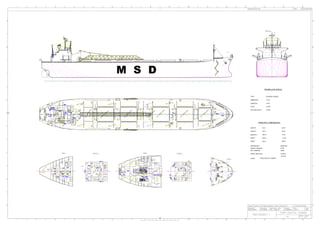
  • 1. MIDSHIP SECTION M.R. S.R. A.P. H.B. H.B. BOAT LIFE H.B. H.B. F.M. PROFILE BOSUN STORE BOSUN STORE M S D C.L C.C P.P.F. A.H A.H L.H. L.H. M.H. UP L.H. A.H A.H L.H. A.H L.H. M.H. FAINT A.H DECK STORE LAMP RM. BOS'N STORE C.L. DN A.H A.H L.H. L.H. A.H A.H M.H. L.H. UP C.L C.C P.P.F. FAN ROOM FAN ROOM NO . 3 CARG O HATCH NO . 2 CARG O HATCH NO . 1 CARG O HATCH NO. 2 T. S. T. (S) NO. 1 T. S. T. (P) NO. 2 T. S. T. (P) NO. 1 T. S. T. (S) PILOT LADD ACCOMM LADD C C C.C. B.C F.L. UP. P.C PROT LADD C.C C.L. ACCOMM LADD C.C. TALLY EMERGE RM. STORE CONTROL ROOM M.H. F.L F.L EL. EL. P.C. R.M. DN DN V.T. WORK SHOP V.T. DN A.H. L.H. L.H. A.H. UP UP STORE STORE PROV. PROV. LOBBY HOSPITAL REF. FISH MEAT M. RM. V.T DN V.T STAT FIRE UP. UP GYM SPACE A.H. A.H. L.M. VEG. HOSP. W.C. V.T. DRY RM. PIPE S.P. E.G. C. DECK FAN RM. R.H. L.H. L.H. A.H. A.H. L.H. A.H. A.H. UP M.H. V. C.L. C.C. NO. 5 T. S. T. (P) H.B. ENGINE OPEN LO O P BELT CASING O PENING VENT O PENING VENT O PENING NO . 6 CARG O HATCH NO . 5 CARG O HATCH NO . 4 CARG O HATCH NO. 4 T. S. T. (S) D.O. SERV. PIPE NO. 4 T. S. T. (P) NO.7CARGO HATCH F.L. P.C. (VOID) NO. 5 T. S. T. (P) NO. 3 T. S. T. (P) NO. 3 T. S. T. (S) LENGTH LENGTH BREADTH DEPTH DRAFT CLASS SPEED TRIAL MAX 150M COASTAL TANKER DEADWEIGHT GROSS TONNAGE NET TONNAGE 60939TON 37168 14828 20 knots 18 knots PROPELLER SPECS PRINCIPAL DIMENSIONS (O.A.) (B.P.) (MLD.) (MLD.) (EXT.) 150 M 143 M 11.9 M 24 M 9.95 M 3RD DECK LOW. BRI DECK D. ENGINE CONTROL RM. U. GALLEY U. D. C. L. A.P. E.F.P. RM. 10 15 20 25 30 35 C. L. 40 C. L. 10 D. CREW'S W.C. V.T. D. U. H.B. SAIL (D) SAIL (C) SAIL SAIL CREW'S (A) SHOW RM.(B) D. BOS'N U V.T. O/M (A) O/M (B) O/M (C) 15 20 AIR COND. RM. LKR. JUMP 25 30 V.T. D. V.T. V.T. D. U. BATT. RM. OIL OIL OIL FITT. CREW'S CREW'S SPARE RM. CARPENT 35 C. L. 40 SPARE RM. NO.1 OIL ENGINEOPEN H.B.H.B. UPP. A.P.T.(S.W .) ENG INE O PEN 2ND DECK UPP. BRI DECK WORK SHOP STORE RM. AUX. MACHINERY ROOM U H.B. U U C. L. 0 A.P.A.P. RM. 5 STEER. GEAR U 10 15 20 25 30 35 40 45 50 C.L. 10 15 20 25 U D D V.C D W.C. OFF. U 30 DN. D U D H.B. U D. SPARE SPARE RM. 2/OFF. F.H. 3/OFF. C/OFF. C/OFF. BED RM. ELEC. EQUIPMENT ROOM C/OFF. DAY RM. UP V.T. OFF'S SHOW V.T. RM. 35 LINEN LKR. 3/ENG. 40 V.T. D DAY RM. C/ENG. C.L. ELECT ENG. P/O 1/ENG. DAY RM. 1/ENG. RM. BED 1/ENG. LAV. C/ENG LAV. C/ENG. BED RM. DRI W. T. (S) NO. 2 F. W . T. (P) ENGINEO PEN LOOP BELT CASING ENG INE O PEN NO.1F.W.T.(P) NO.3D.O.T.(S) WIND D. F.N. C. L. 115 120 125 130 135 F.P F.P. U. 140 R.M. S.D. 145 150 C. L. D. WIND F.L. F'CLE DECK P.C. F.L. F.L. F.L. P.C. F.L. F.L. B.L. 0 AP 10 15 20 25 30 35 40 45 50 55 60 65 70 75 80 85 90 95 100 105 110 115 120 130 135 140 FP 150125 0 AP 10 15 20 25 30 35 40 45 50 55 60 65 70 75 80 85 90 95 100 105 110 115 120 130 135 140 FP 150125 TYPE IMMERSION DIAMETER PITCH EXP AREA RATIO B-SERIES 3 BLADE 7.8 M 2.34 M 3.9 M 0.55 M
  • 2. Tanks and Compartments TANKS AND COMPARTMENTS AP FP Baseline STR ER PUMPROOM FOT 1 PS FOT 1 SB FOT 2 PS FOT 2 SB FWD COMP BT PS (FWD) BT SB (FWD) SLOPCOMPSLOPTK FWT PS (1) FWT BS (1) HOLD 1COT (1) SD BT PS (1) DB BT PS (1) DB BT SB (1) SD BT SB (1) HOLD 2COT (2) SD BT PS (2) DB BT PS (2) SD BT SB (2) DB BT SB (2) HOLD 3COT (3) SD BT PS (3) DB BT PS (3) SD BT SB (3) DB BT SB (3) HOLD 4COT (4) SD BT PS (4) DB BT PS (4) SD BT SB (4) DB BT SB (4) HOLD 5COT (5) SD BT PS (5) DB BT PS (5) SD BT SB (5) DB BT SB (5) HOLD 6COT (6) SD BT PS (6) DB BT PS (6) SD BT SB (6) DB BT SB (6) Zero pt. AP FP Baseline STR ER PUMPROOMFOT 1 PSFOT 1 SB FOT 2 PSFOT 2 SB FWD COMPBT PS (FWD)BT SB (FWD)SLOPCOMPSLOPTKFWT PS (1)FWT BS (1)HOLD 1COT (1)SD BT PS (1) DB BT PS (1)DB BT SB (1) SD BT SB (1) HOLD 2COT (2)SD BT PS (2) DB BT PS (2) SD BT SB (2) DB BT SB (2) HOLD 3COT (3)SD BT PS (3) DB BT PS (3) SD BT SB (3) DB BT SB (3) HOLD 4COT (4)SD BT PS (4) DB BT PS (4) SD BT SB (4) DB BT SB (4) HOLD 5COT (5)SD BT PS (5) DB BT PS (5) SD BT SB (5) DB BT SB (5) HOLD 6COT (6)SD BT PS (6) DB BT PS (6) SD BT SB (6) DB BT SB (6) Zero pt.
  • 4. SYSTEM HEAD HEAD LOSS CALCULATION PUMP SIZING FITTING/VALVE CONDITION K FACTOR Subject Value Units 45° Elbow Standard radius 0.3 Total Volume Tank (ƩV) 16895.57 m 3 Standard radius 0.6 Discharge Time 4 hours 14400 (s) 4 x 3600 Long radius 0.3 Flow rate (Q) - For Ship 0.293 m 3 /s Return Bend 0.8 Diameter 0.5 m Socket or Coupler Screwed type 0.03 Velocity 1.494 m/s Along line of flow 0.3 Area 0.196 m 2 Through side 0.8 Gate Valve Fully open 0.2 Dynamic Viscosity, ( µ ) 0.09 Pa. s Fully open 6 Density, (ρ) 888.30 Kg/m 3 from Density Table ¾ open 8 Kinematic Viscosity (γ) 0.000004 ½ open 12 ¼ open 24 Re 186737.003 Hinged or swing disc 1.7 (10^6)/ Re 5.355 Ball or poppet type 4 Roughness Value ε 0.045 mm Hinged or swing disc 3 Relative roughness εR 0.00009 Ball or poppet type 7 Contracting 0 (negligible) Laminar 0.000342728 Enlarging 0.75 Turbulent 0.005509531 Sudden contraction 0.25 Sudden enlargement 1 Length from shore 120 m Tank to pipe line Sudden entrance 0.5 Head Static 30 m Pipe line to tank Sudden exit 1 Total Head (ƩHT) 204682.849 Pipe line γ = µ/ρ Formula Q/v Hsystem= HfL+Hfv+Hfstatic HfL = ﴾ f L/d ﴿ v 2 /2g Hfv= ΣK.V 2 /2g Hfstatic= Given in Question (30) 90° Elbow Tee Globe Valve Check Valve Foot Valve with strainer Gradual transition Head Loss Calculation Sheet Not more than 2 m/s CARGO PIPING SYSTEM MARINE SYSTEM DESIGN
  • 5. SYSTEM HEAD HEAD LOSS CALCULATION PUMP SIZING Volume m 3 1129.447 1129.447 1486.584 1486.583 1486.584 1486.584 1495.512 1495.512 1489.057 1489.058 1360.599 1360.599 16895.566 Crude Oil particular 9.8100 888.3000 0.0900 0.000004 LOA= CARGO PUMP= TYPE= RPM= HfL = ﴾ f L/d ﴿ v 2 /2g Hfv= ΣK.V 2 /2g Hfstatic= Given in Question (30) Hsystem= HfL+Hfv+Hfstatic Pump = Gravity.Density.(HfS + Hfstatic) Cargo Oil Tank 4 (S) Cargo Oil Tank 4 (P) Cargo Oil Tank 5 (S) Cargo Oil Tank 5 (P) Total volume Tank Kinematic Viscosity, m2 /s 150M 4x PUMP Split Casing Centrifugal Pumps 1480RPM Dynamic Viscosity Pa.SDensityGravity ITEM Cargo Oil Tank 1 (S) Cargo Oil Tank 1 (P) Cargo Oil Tank 2 (P) Cargo Oil Tank 2 (S) Cargo Oil Tank 6 (S) Cargo Oil Tank 6 (P) General Particular Cargo Oil Tank 3 (S) Cargo Oil Tank 3 (P) CARGO PIPING SYSTEM MARINE SYSTEM DESIGN
  • 6. SYSTEM HEAD HEAD LOSS CALCULATION PUMP SIZING HfS Item Type of Fitting Qty K factor ΣK factor L HfL Hfv HfL+Hfv Hfstatic Head System Ppump(kPa) 1 sudden entrance 1 0.5 0.5 2 Gate Valve 2 0.2 0.4 3 Tee Along Line of Flow 1 0.3 0.3 4 90° Elbow Standard Radius 1 0.6 0.6 5 Main Pipeline 1.8 138.6 0.1737199 0.2047 0.378465 30 30.3785 264724.7214 Item Type of Fitting Qty K factor ΣK factor L HfL Hfv HfL+Hfv Hfstatic Head System Ppump(kPa) 1 sudden entrance 1 0.5 0.5 2 Gate Valve 2 0.2 0.4 3 90° Elbow Standard Radius 1 0.6 0.6 4 Main Pipeline 1.5 138.4 0.173469222 0.170621 0.34409 30 30.34409 264425.1707 Item Type of Fitting Qty K factor ΣK factor L HfL Hfv HfL+Hfv Hfstatic Head System Ppump(kPa) 1 sudden entrance 1 0.5 0.5 2 Gate Valve 2 0.2 0.4 3 Tee Along Line of Flow 2 0.3 0.6 4 90° Elbow Standard Radius 1 0.6 0.6 5 Main Pipeline 2.1 153.25 0.192082068 0.23887 0.430952 30 30.43095 265182.0997 Item Type of Fitting Qty K factor ΣK factor L HfL Hfv HfL+Hfv Hfstatic Head System Ppump(kPa) 1 sudden entrance 1 0.5 0.5 0 2 Gate Valve 3 0.2 0.6 0 3 90° Elbow Standard Radius 1 0.6 0.6 0 4 Main Pipeline 1.7 153.05 0.19183139 0.193371 0.385202 30 30.3852 264783.4269 Item Type of Fitting Qty K factor ΣK factor L HfL Hfv HfL+Hfv Hfstatic Head System Ppump(kPa) 1 sudden entrance 1 0.5 0.5 2 Gate Valve 3 0.2 0.6 3 Tee Along Line of Flow 3 0.3 0.9 4 90° Elbow Standard Radius 1 0.6 0.6 5 Main Pipeline 2.6 169.52 0.212474729 0.295743 0.508218 30 30.50822 265855.4163 CARGO TANK 3(S) CARGO TANK 3(P) CARGO TANK 1(S) CARGO TANK 1(P) CARGO TANK 2(S) CARGO TANK 2(P) CARGO PIPING SYSTEM MARINE SYSTEM DESIGN
  • 7. SYSTEM HEAD HEAD LOSS CALCULATION PUMP SIZING Item Type of Fitting Qty K factor ΣK factor L HfL Hfv HfL+Hfv Hfstatic Head System Ppump(kPa) 1 sudden entrance 1 0.5 0.5 2 Gate Valve 4 0.2 0.8 3 90° Elbow Standard Radius 1 0.6 0.6 4 Main Pipeline 1.9 169.3 0.212198983 0.21612 0.428319 30 30.42832 265159.1588 Item Type of Fitting Qty K factor ΣK factor L HfL Hfv HfL+Hfv Hfstatic Head System Ppump(kPa) 1 sudden entrance 1 0.5 0.5 2 Gate Valve 4 0.2 0.8 3 Tee Along Line of Flow 4 0.3 1.2 4 90° Elbow Standard Radius 1 0.6 0.6 5 Main Pipeline 3.1 185.73 0.232792186 0.352617 0.585409 30 30.58541 266528.0775 Item Type of Fitting Qty K factor ΣK factor L HfL Hfv HfL+Hfv Hfstatic Head System Ppump(kPa) 1 sudden entrance 1 0.5 0.5 2 Gate Valve 4 0.2 0.8 3 90° Elbow Standard Radius 1 0.6 0.6 4 Main Pipeline 1.9 185.51 0.23251644 0.21612 0.448637 30 30.44864 265336.2096 Item Type of Fitting Qty K factor ΣK factor L HfL Hfv HfL+Hfv Hfstatic Head System Ppump(kPa) 1 sudden entrance 1 0.5 0.5 2 Gate Valve 5 0.2 1 3 Tee Along Line of Flow 5 0.3 1.5 4 90° Elbow Standard Radius 1 0.6 0.6 5 Main Pipeline 3.6 202.42 0.253711271 0.409491 0.663202 30 30.6632 267205.9815 Item Type of Fitting Qty K factor ΣK factor L HfL Hfv HfL+Hfv Hfstatic Head System Ppump(kPa) 1 sudden entrance 1 0.5 0.5 2 Gate Valve 5 0.2 1 3 90° Elbow Standard Radius 1 0.6 0.6 4 Main Pipeline 2.1 202.2 0.253435525 0.23887 0.492305 30 30.49231 265716.7474 CARGO TANK 5(P) CARGO TANK 4(S) CARGO TANK 4(P) CARGO TANK 5(S) CARGO PIPING SYSTEM MARINE SYSTEM DESIGN
  • 8. SYSTEM HEAD HEAD LOSS CALCULATION PUMP SIZING Item Type of Fitting Qty K factor ΣK factor L HfL Hfv HfL+Hfv Hfstatic Head System Ppump(kPa) 1 sudden entrance 1 0.5 0.5 2 Gate Valve 5 0.2 1 3 Tee Along Line of Flow 6 0.3 1.8 4 90° Elbow Standard Radius 1 0.6 0.6 5 Main Pipeline 3.9 219.74 0.275419991 0.443615 0.719035 30 30.71904 267692.5224 Item Type of Fitting Qty K factor ΣK factor L HfL Hfv HfL+Hfv Hfstatic Head System Ppump(kPa) 1 sudden entrance 1 0.5 0.5 2 Gate Valve 5 0.2 1 3 90° Elbow Standard Radius 1 0.6 0.6 4 Main Pipeline 2.1 219.52 0.275144246 0.23887 0.514014 30 30.51401 265905.922 1 m 3.28084 ft Q = 0.2933 m3 /s Dia, (m)= 0.5 m 39.37008 inch 4649.2139 gpm 19.68503935 inch 1 m3 /s = 15850 gpm 4x Pumps 1162.303477 Area, (m 2 ) 0.1963 1 Pumps= 3962.5 Item Q (Flow Rate) H. loss ( pipe +fitting) A A2 Q2 H.fluid H.static H.system Q (gpm) H.S (Feet) 1 0 0.7190 0.1963 0.0386 0.000 0 30 30 0 98.4252 2 0.15 0.7190 0.1963 0.0386 0.023 0.419636099 30 30.41964 594.375 99.80196 3 0.3 0.7190 0.1963 0.0386 0.090 1.678544394 30 31.67854 1188.75 103.9322 4 0.45 0.7190 0.1963 0.0386 0.203 3.776724887 30 33.77672 1783.125 110.816 5 0.6 0.7190 0.1963 0.0386 0.360 6.714177577 30 36.71418 2377.5 120.4533 6 0.75 0.7190 0.1963 0.0386 0.563 10.49090246 30 40.4909 2971.875 132.8442 7 0.9 0.7190 0.1963 0.0386 0.810 15.10689955 30 45.1069 3566.25 147.9885 8 1.05 0.7190 0.1963 0.0386 1.103 20.56216883 30 50.56217 4160.625 165.8864 9 1.2 0.7190 0.1963 0.0386 1.440 26.85671031 30 56.85671 4755 186.5378 10 1.35 0.7190 0.1963 0.0386 1.823 33.99052399 30 63.99052 5349.375 209.9427 H = 56.8567 m 186.5377695 ft CARGO TANK 6(S) CARGO TANK 6(P) CARGO PIPING SYSTEM MARINE SYSTEM DESIGN
  • 9. SYSTEM HEAD HEAD LOSS CALCULATION PUMP SIZING Item Q (GPM) Q (m 3 /hr) Q (m 3 /s) H.system (m) Cargo Tank Cargo TankH. loss( pipe +fitting) 1 0.0 0 0 30.00 1 (S) 6(S) 0.7190 2 594.4 0 0.15 30.42 1 (P) 6(P) 0.5140 3 1188.8 0 0.3 31.68 2 (S) 4 1783.1 0 0.45 33.78 2 (P) 5 2377.5 0 0.6 36.71 3 (S) 6 2971.9 0 0.75 40.49 3 (P) 7 3566.3 0 0.9 45.11 4 (S) 8 4160.6 0 1.05 50.56 4 (P) 9 4755.0 0 1.2 56.86 5 (S) 10 5349.4 0 1.35 63.99 5 (P) MAX 0.7190 0.4283 0.5854 0.4486 0.6632 0.4923 0.5082 H. loss( pipe +fitting) 0.3785 0.3441 0.4310 0.3852 0 0.15 0.3 0.45 0.6 0.75 0.9 1.05 1.2 1.35 0 50 100 150 200 250 0 1000 2000 3000 4000 5000 6000 SystemHead(Feet) Flow Rate (gpm)) Head System CARGO PIPING SYSTEM MARINE SYSTEM DESIGN
  • 10. SYSTEM HEAD HEAD LOSS CALCULATION PUMP SIZING 1 m 3.28084 ft Dia, (m)= 0.5 m 39.37008 inch 19.68503935 inch 1 m3 /s = 15850 gpm Area, (m2 ) 0.1963 Q = 0.2933 m3 /s H = 56.8567 m 4649.2139 gpm 186.5377695 ft 1056.129888 m3 /h Qtotal= 18596.85563 gpm 4x pump= 4600 m3 /h 0 50 100 150 200 250 0 1000 2000 3000 4000 5000 6000 Old Flow Rate 4649.2139 gpm System Head 109 ft New Flow Rate 5000 gpm Pump Efficiency = 83 % CARGO PIPING SYSTEM MARINE SYSTEM DESIGN
  • 11. SYSTEM HEAD HEAD LOSS CALCULATION PUMP SIZING 2) Actual discharge time Qnew= 20000 gpm H.pump= 186.5378 1.26183 m 3 /s 56.8567 Impeller size= 14 inch Power= 0.3556 m ft 83.00% T= 3.719371126 m 3) New flow rate is 1.261829653 m 3 /s 150.0000 hp 111.8549808 kW hrs // 3 hours 43 minutes 54 seconds Pump Efficiency = PUMP SPECS System Head 109 ft Old Flow Rate 1056 m3/h 𝑇𝑖𝑚𝑒 = 𝑉𝑜𝑙𝑢𝑚𝑒 𝐹𝑙𝑜𝑤 𝑅𝑎𝑡𝑒 (𝑛𝑒𝑤) 𝐹𝑙𝑜𝑤 𝑅𝑎𝑡𝑒 (𝑛𝑒𝑤) = 𝑉𝑜𝑙𝑢𝑚𝑒 𝑇𝑖𝑚𝑒 CARGO PIPING SYSTEM MARINE SYSTEM DESIGN
  • 12. B.L. 0 AP 10 15 20 25 30 35 40 45 50 55 60 65 70 75 80 85 90 95 100 105 110 115 120 130 135 140 FP 150125 M.R. S.R. H.B. H 1 2 3 G F E 4 5 6 7 D C B A 31 2 54 876 Title/Name, designation, material, dimension etc Checked by 10 11 12 Designed by Itemref 13 Quantity FilenameApproved by - date 14 15 Article No./Reference Date 16 Edition Sheet Scale H G F E 11109 1312 RevNo Revision note D C B Checked 15 1614 Date Signature A EN, HAMDAN PIPING DESIGN NAIM, JAMAL,IZWAFI XXX MSD PROJECT 2 XXX - 10/4/2019 GROUP 2 10/4/19 L01 1/1 1:400
  • 13. VENTILATION SYSTEM Ventilation ρw 1000 kg/m3 ε (mm) = 0.15 γ = 0.00005 ρa 1.099 kg/m3 εR = # Item Type of Fitting Qty K factor ΣK factor ε (mm) Re Lcompt Volume (m3) ACHr Q (m3/s) Φ (m) Area m2 vel. m/s εR fturbulant 2f.L/D 1 Bend 0 0.75 0 2 Exit Flap 1 0.65 0.65 3 Volume Control 1 0.65 0.65 Duct 1.3 0.15 964637.6857 24.6 4545.748 15 18.94061667 0.5 0.196349541 96.46376857 0.0006 0.018444485 1.814937356 0.158763372 # Item Type of Fitting Qty K factor ΣK factor ε (mm) Re Lcompt Volume (m3) ACHr Q (m3/s) Φ (m) Area m2 vel. m/s εR fturbulant 2f.L/D 1 Bend 2 0.75 1.5 2 Exit Flap 1 0.65 0.65 3 Volume Control Damper 0 0.65 0 4 Concentric reducer 2 0.8 1.6 Duct 3.75 0.15 742028.989 24.6 4545.748 15 18.94061667 0.65 0.331830724 57.079153 0.000461538 0.017573588 1.330185461 0.258928923 # Item Type of Fitting Qty K factor ΣK factor ε (mm) Re Lcompt Volume (m3) ACHr Q (m3/s) Φ (m) Area m2 vel. m/s εR fturbulant 2f.L/D 1 Bend 2 0.75 1.5 2 Exit Flap 1 0.65 0.65 3 Volume Control Damper 0 0.65 0 4 Concentric reducer 2 0.8 1.6 Duct 3.75 0.15 742028.989 24.6 4545.748 15 18.94061667 0.65 0.331830724 57.079153 0.000461538 0.017573588 1.330185461 0.258928923 # Item Type of Fitting Qty K factor ΣK factor ε (mm) Re Lcompt Volume (m3) ACHr Q (m3/s) Φ (m) Area m2 vel. m/s εR fturbulant 2f.L/D 1 90 degree Bend 6 0.75 4.5 2 Exit Flap 1 0.75 0.75 3 Inlet grill and cowling 2 1 2 4 fire damper 1 0.6 0.6 5 expansion joint 4 0.65 2.6 6 Concentric reducer 2 0.8 1.6 7 Wye 0 0.09 0 8 damper gate round 1 0.045 0.045 Duct 12.095 0.15 1205797.107 50 56.82185 1.2 1.130973355 50.24154613 0.00025 0.015398487 1.283207269 0.681865814 Section1Section2Section3MainDuct (2f.L/D + ΣK)/2g (2f.L/D + ΣK)/2g (2f.L/D + ΣK)/2g (2f.L/D + ΣK)/2g 2 4 ( ) 2 air water FLV StaticHeadLoss metres gd r r = 2 ( ) 2 air water V VelocityHeadLoss k metres g r r = VENTILATION SYSTEM DESIGN
  • 14. VENTILATION SYSTEM # Q Q2 Area2 (m4 ) Hsystem PL (Pa) 1 0 0 1.2791 0.00 0 2 1 1 1.2791 0.0012 11.4503154 3 2 4 1.2791 0.0047 45.8012616 4 3 9 1.2791 0.0105 103.0528386 5 4 16 1.2791 0.0187 183.2050464 6 5 25 1.2791 0.0292 286.257885 7 6 36 1.2791 0.001493 0.0420 412.2113544 8 7 49 1.2791 0.001493 0.0572 561.0654547 9 8 64 1.2791 0.001493 0.0747 732.8201857 10 9 81 1.2791 0.001493 0.0945 927.4755475 11 10 100 1.2791 0.001493 0.1167 1145.03154 12 11 121 1.2791 0.001493 0.1412 1385.488164 PARAMETERS VALUE UNITS Engine Power @ 18knt MTU 8000kW 8000 kW η 98.20% % H 160 kW ρ air 1.099 kg/m3 ρ water 1000 kg/m3 Cp 0.017 kW.min/kg.degC ΔT 12 ᵒC Volume Engine Room 4545.748 m3 Combustion Air 0.107 m3/min/brake KW Routing Factor 2.5 F Ventilation Air Flow 1784.420652 m3/min H/D*Cp*ΔT 713.6612607 H= P*(1-EFF) 160 Parameters Value Units Ventilation Air Required 1784.420652 m3/min Flow Rate 18.94061667 m³/s Velocity 96.46376857 m/s Diameter² 0.25 m2 Diameter 0.5 m Area 0.196349541 m² Kinematic Viscosity 0.00001606 Reynolds Numbers 964637.6857 F Laminar Absolute Roughness 0.15 m Relative Roughness εR 0.0006 m F Turbulence 0.018444485 0.001492977 Σ(2f.L/D + ΣK)ρa/2g/ρw 0.001492977 0.001492977 0.001492977 0.001492977 0.001492977 0 0.5 1 1.5 2 2.5 3 0 2 4 6 8 10 12 HSYSTEM HSYSTEM Hsystem (m) Q (m3/s) Pascalsg g vk g vk g vk dg vLf P w w ann w a L                   )) 2 .... 22 (( 2 4 ( 22 22 2 11 2 VENTILATION SYSTEM DESIGN
  • 15. M.R. S.R. H.B. 0 AP 10 15 20 25 30 35 U C. L. 0 10 15 20 25 30 35 40 45 50 U D DN. UP DRI W. T. (S) NO. 2 F. W . T. (P) LOOP BELT CASING NO.1F.W.T.(P) NO.3D.O.T.(S)
  • 16. Date: 30/5/2019 Network 50Hz 415V 3 Phase 4-Wire System CABLING AND POWERING AWG STANDARD/IEC STANDARD AC / DC Diversity Factor Diversifie d (kW) Voltage (V) Current (A) Diversi ty Factor Diversified (kW) Voltage (V) Current (A) Diversity Factor Diversified (kW) Voltage (V) Current (A) Cable Size (mm 2 ) AWG 1 Bilge/ Ballast Pump 2 5.5 11 AC 3 0.8 8.8 440 20.00 0.8 8.8 440 20.00 0.8 8.8 440 20.00 2.5 13 2 General Service/Fire Pump 2 5.5 11 AC 3 0.8 8.8 440 20.00 0.8 8.8 440 20.00 0.8 8.8 440 20.00 1.5 15 3 Engine Room Blower Fan No.1 - Port1 4 4 AC 3 1 4 400 10.00 1 4 400 10.00 1 4 400 10.00 4 11 4 Engine Room Blower Fan No.1 - Stbd1 4 4 AC 3 1 4 400 10.00 1 4 400 10.00 1 4 400 10.00 4 11 5 Sewage Pump 2 1.4 2.8 AC 3 1 2.8 440 6.36 1 2.8 440 6.36 1 2.8 440 6.36 1.5 15 6 Sea Water Pump (Domestic) 2 4 8 AC 3 0.5 4 440 9.09 0.5 4 440 9.09 0.5 4 440 9.09 1.5 15 7 Fuel Oil Transfer Pump 2 2.238 4.476 AC 3 0.7 3.1332 440 7.12 1 4.476 440 10.17 0.7 3.1332 440 7.12 1.5 15 8 Fresh Water Pump 2 2.2 4.4 AC 3 0.5 2.2 440 5.00 0.5 2.2 440 5.00 0.5 2.2 440 5.00 1.5 15 9 Oil Bilge Separator 1 0.4 0.4 AC 1 0.8 0.32 120 2.67 0 0 0 0.00 0.8 0.32 120 2.67 1.5 15 10 Steering Gear 1 2.5 2.5 AC 3 0.8 2 400 5.00 0 0 0 0.00 0.8 2 400 5.00 16 5 11 Winch & Power Pack 2 10 20 AC 3 0.8 16 440 36.36 0.8 16 440 36.36 0.8 16 440 36.36 6 9 12 Floor Standing Air-Con (Air-Con Plant)4 33.25 133 AC 3 1 133 400 332.50 1 133 400 332.50 1 133 400 332.50 1.5 15 13 Battery Charger 2 0.72 1.44 DC 1 0.25 0.36 120 3.00 0 0 0 0.00 0.25 0.36 120 3.00 1 15 14 Navigation Light Panel 2 0.25 0.5 AC 1 1 0.5 120 4.17 1 0.5 120 4.17 1 0.5 120 4.17 1 17 15 Radio Battery Charger 2 0.72 1.44 DC 1 0.25 0.36 120 3.00 0.25 0.36 120 3.00 0.25 0.36 120 3.00 1 17 16 Emergency Battery Charger 4 0.72 2.88 DC 1 0.5 1.44 120 12.00 0.5 1.44 120 12.00 0.5 1.44 120 12.00 1.5 15 17 Lighting 22 0.02 0.8 AC 1 1 0.8 120 6.67 1 0.8 120 6.67 1 0.8 120 6.67 1.5 15 18 Socket Outlet 110 0.02 2.2 AC 1 0.5 1.1 120 9.17 0.5 1.1 120 9.17 0.5 1.1 120 9.17 1 17 19 Toilet/Bath Room Fan 2 0.2 0.4 AC 1 1 0.4 120 3.33 1 0.4 120 3.33 1 0.4 120 3.33 1.5 15 20 Galley Fan 2 0.75 1.5 AC 1 0.4 0.6 120 5.00 0.4 0.6 120 5.00 0.4 0.6 120 5.00 1.5 15 21 Searchlight 4 1 4 AC 1 0.8 3.2 120 26.67 1 4 120 33.33 1 4 120 33.33 2.5 13 22 Floodlight 8 0.5 4 DC 1 0.6 2.4 120 20.00 1 4 120 33.33 1 4 120 33.33 2.5 13 23 Water Heater Bath Room 4 3.72 14.88 DC 1 0.5 7.44 240 31.00 0.5 7.44 240 31.00 0.5 7.44 240 31.00 1.5 15 24 Crane 1 600 600 AC 3 0.8 480 280 1714.29 0.9 540 280 1928.57 1 600 280 2142.86 25 3 25 Ship Whistle 1 1 1 DC 1 0.1 0.1 120 0.83 0 0 0 0.00 0.1 0.1 120 0.83 1 17 26 Hot Plate 1 3.5 3.5 AC 1 0.9 3.15 240 13.13 0 0 0 0.00 0.9 3.15 240 13.13 2.5 13 27 Rice Cooker 4 1.5 6 DC 1 1 6 240 25.00 0 0 0 0.00 1 6 240 25.00 1 17 28 Galley Freezer 2 1.5 3 AC 1 1 3 240 12.50 1 3 240 12.50 1 3 240 12.50 2.5 13 29 Fire Alarm System 4 0.25 1 DC 1 1 1 120 8.33 1 1 120 8.33 1 1 120 8.33 2.5 17 30 Steering Gear Ventilation Fan 1 4 4 DC 1 1 4 240 16.67 1 4 240 16.67 1 4 240 16.67 4 11 31 Radio communication 3 0.25 0.75 AC 1 0.25 0.1875 120 1.56 0.19 0.1425 120 1.19 0.25 0.1875 120 1.56 1.5 15 32 Refrigerator Compressor 2 3 6 DC 1 1 6 240 25.00 0 0 0 0.00 1 6 240 25.00 1.5 15 33 Cargo Oil Pump 4 112 448 AC 3 0.8 358.4 440 814.55 0 0 0 0.00 0.8 358.4 440 814.55 17 Installed (kW) 1312.866 65.643 1378.509 (%) 35.555 37.843 41.675 746.645 794.701 875.165 PieceLoad Description Item No. Max Demand (at Sea) (kW) Max Demand (Harbour) (kW) Normal at Sea Harbour Condition Consumption Total (kW) Phase Consumption Single (kW) 711.091 756.859 Operation Condition Max Demand (Operation) (kW) 833.491Summary Design Margin (5%) Total 1 Generator 60 kW 1458.61324.51244.4 Page 1 of 1