Critical heat flux enhancement in pool boiling with al2 o3 water nanofluid
20040086056
1. Thermographic Imaging of Material Loss in Boiler Water-
Wall Tubing by Application of ScanningLine Source
K. Elliott Cramer and William P. Winfree
National Aeronautics and Space Administration
Langley Research Center
3B East Taylor St.
Mail Stop 231
Hampton, VA 23681
ABSTRACT
Localized wall thinning due to corrosion in utility boiler water-wall tubing is a significant inspection
concern for boiler operators. Historically, conventional ultrasonics has been used for inspection of these
tubes. This technique has proven to be very manpower and time intensive. This has resulted in a “spot
check” approach to inspections,documentingthickness measurements over a relatively small percentage of
the total boiler wall area.
NASA Langley Research Center has developed a thermal NDE technique designed to image and
quantitatively characterize the amount of material thinning present in steel tubing. The technique involves
the movement of a thermal line source across the outer surface of the tubing followed by an infrared imager
at a fixed distance behind the line source. Quantitative images of the material loss due to corrosion are
reconstructed from measurementsof the induced surface temperature variations. This paper will present a
discussion of the development of the thermal imaging system as well as the techniques used to reconstruct
images of flaws. The applicationof the thermal line source coupled with the analysis technique represents a
significant improvement in the inspection speed for large structuressuch as boiler water-walls.
A theoretical basis for the technique will be presented which explains the quantitative nature of the
technique. Further, a dynamic calibration system will be presented for the technique that allows the
extraction of thickness information from the temperature data. Additionally, the results of applying this
technology to actual water-wall tubing samplesand in situ inspectionswill be presented.
Keywords: Infrared, Thermal, NDE, Corrosion
1. INTRODUCTION
The inspection of large civil structures,such as utility water-wall tubing in boilers is a major challenge for
power plant operators. Because of the size of these structures (typically 9,000 m2 interior surface area)
conventional NDE techniques such as ultrasonics, eddy currents and even conventional thermography, are
limited in their usefulness. Ultrasonic and eddy current techniques typically use small area probes
(approximately 6 cm2 inspection area) which limit the total practical inspection area to only a small
percentage of the boiler water-wall. Additionally,the use of these techniques is very manpower intensive,
imposing a practical limit on the total inspection area.
Recent developments have shown the advantages of infrared (IR) thermography for the detection of
corrosion and disbonds in aircraft structure^.'.^.^ These techniques have typically involved heating with an
IR source and the concurrent imaging of the induced temperature change with an IR camera. This offers a
rapid method for detecting corrosion and quantifying its extent in single layer structures. In this
application, the heating and imaging components of the system remain stationary durin the measurement
this technique include the expense of the infrared camera and the large power requirement for the infrared
cycle. While conventional thermographycan inspect larger areas at a time (normally 1 mL) disadvantages of
2. heater. This latter disadvantage becomes especially significant when inspecting large, thick structures
which are poor thermal conductors,such as water-wall tubing.
This paper examines an alternate method for thermographicallyobtaining the thickness of the structure. It
is patterned after a technique described by Maldague4where a sample moves at a constant velocity past a
fixed linear heat source and is observed by an IR imager. Maldague demonstrates that the method is
effective for the detection of disbonding in laminatedsamples.
Included are results from an alternate implementationof this system where the specimen is stationary and
the line heat source and IR camera are translated together at a constant velocity. This implementation
allows the rapid inspection of large structures such as power plant boilers. From the output of the IR
camera, an image is reconstructed which yields the induced temperature changes at a fixed distance behind
the line heat source.
This method has several distinct advantages over conventional NDE techniques. First, since the IR heater is
held close to the object of interest, enabling a more efficient coupling of the energy into the specimen, the
power requirements are reduced while not impacting sensitivity. This method also enables very high
inspection rates (in steel, speeds of 5 c d s can be achieved). An additional advantage is that a linear may
of detectors can replace the IR camera, significantlyreducing the cost of the system.
Data will be presented from laboratory measurements on specimens with fabricated thinning to simulate
material loss due to corrosion. A theoretical basis for relating the amount of thinning to the induced
temperature change has been developed. The results of applying this technology to actual water-wall
tubing samples and in siru boiler inspectionswill be shown.
2. EXPERIMENTALTECHNIQUE
The current implementationof the scanned line source and imager is shown in Figure 1.The IR imager is a
commercial radiometer with a cooled 256x256-element InSb (Indium - Antimonide) focal plane may
detector. The radiometer's noise equivalent temperature difference (NEAT), cited by the manufacturer, is
0.025"C when operating the detector in the 3 to 5 micrometer wavelength range. The radiometer produces
images at both 30 frames per second output (video frame rate, in an RS170, format compatible with
standard video equipment) and 60 frames per second output in a 12-bit, RS422 digital format. External
optics, consisting of a wide-angle lens, using germaniumoptical elements, were used to increase the system
field-of-view by a factor of approximatelytwo. The expanded field-of-viewof this lens is 22" in both the
horizontal and vertical directions.
Focusing a commercially available 3000-watt quartz lamp, with an elliptical reflector behind the quartz
tube, approximates a line of heat. The heat source and the IR imager are attached to a commercial linear
scanning bridge. Quantitative time based analysis requires synchronizationbetween the IR imager, the heat
source and the scanning table. This synchronization is achieved by computer control of the application of
heat, motion of the scanning table and data acquisition. The computer can provide any scanning speed up
to 30.5 cdsec. For all cases presented in this paper, the maximum surface temperature change of the
specimen above ambient was less than 10°C.
For low emissivity surfaces, it is necessary to enhance the emissivity by coating the surface. Paint is
typically a good emissivity coating. If the specimen is painted, regardless of color, no additional surface
coating is necessary. Unpainted metallic samples require the addition of an emissivity enhancing coating.
For the results presented here, the metallic samples were treated with either a water washable, nontoxic
paint or a flat black aerosol lacquer to increase the emissivity.
3. Sample Scanning
>e Heater /Bridge Iz
Computer
-IR Camera
Photograph of System
Figure I -Schematic and photograph of experimental setup used to implementmoving line source
technique.
The digital data from the radiometer were acquired and stored at rates up to 60 frames-per-second using a
real-time image processor board in the control computer. The image processor board has 256 megabytes of
image memory available for storage and is capable of real-time floating point processing of the incoming
data. The imaging camera moved with the heat source, enabling data acquisition at a fixed distance from
the source. From a set of acquired images, a single image was then reconstructed that represents the
induced temperature change at a fixed distance from the heat source. The reconstructed image is typically
256 pixels high and up to 1200pixels wide (depending on the physical length of the sample, the speed of
the scanner and the image acquisition rate). This reconstruction is currently done either in real-time by the
image processor, or as post-processing analysis of the data. All of the data presented in the remainder of
the paper (unless otherwise noted) were reconstructed in this manner.
3. STEADY STATEANALYTICALSOLUTIONFOR MOVING LINEAR HEAT
SOURCE
Assuming a medium of thickness L, with an infinitely long line source moving along the surface, and from
a frame of reference moving with and centered on the heat source, it has been shown that the far field
temperature distribution can be given by’:
r
I (x +Ixl>
T(x,z)=-‘ e 2K +2v
-
(1)
I
I’
I
nm e 2K00-V-
LVPC I n = l
I
L i
4. where q is the input heat flux, p is the density, c the specific heat and IC the thermal diffusivity of the
material.
T'
Examination of Equation 1 indicates that when the summation is approximately equal to zero, the
temperature becomes a constant, q/(Lvpc), if x is negative. For lower velocities (v < ~K/L),the condition
necessary for the summation to be approximatelyzero is
5.1 cm
--I tt-0.635cm
Thick
2W L
At higher velocities (v > 2Kn), the condition where the summation is zero is approximated when the
distance behind the line source is equal to the thickness of the plate. When this occurs, the temperature in
the far field behind the source is given by
It can be seen from Equation 3 that the observed temperature of the surface is inversely proportional to the
thickness of the material and can thus be used directly to measure the changes in thickness as long as the
above condition is satisfied.
4. EXPERIMENTALMEASUREMENTSOF SPATIAL RESOLUTIONSPECIMENS
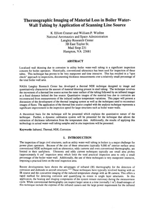
Figure 2 shows a diagram of a steel specimen fabricated to assess the validity of the relationship expressed
in Equation 3. The specimen was 121.9cm in length, 45.7 cm in width with a nominal thickness of 0.635
cm. A 10.2cm wide region spanning the length of the specimen was reduced in thickness to 0.318 cm and
three regions (25.4 cm in length and 5.1 cm in width separated by 12.7 cm) centered on the panel were
reduced in thickness to 0.508 cm, 0.445cm and 0.381 cm respectively.
121.9 cm.
- - -. I
- - -. I
0.318cm
Thick
Figure 2 - Steel specimen, 0.635 cm thick, with three sets of material loss regions, 0.508 cm, 0.455 cm and
0.381 cm deep respectively, centered on the panel and separatedby 12.7cm. Each region is 5.1 cm wide
and 25.4 cm long. A region 10.2cm wide and spanning the length of the specimen was reduced in
thickness to 0.318cm.
5. ReferenceMarker
Figure 3 -Thermal line scanner image and surface temperatureprofile for steel thickness specimen. A
reflective tape reference mark was placed on the surface of the specimenbefore imaging.
Data were acquired on the specimenwhile moving the heat source and imager across the surface at a
velocity of 3.81cmls (2Kn in this case is approximately 1cds). An image acquisition rate of 30 frames
per second was used. Figure 3 shows an image and surface temperatureprofile obtained for a line of
detectors 3.5 cm behind the line of heat. The relationship between the scanning speed and the separation
distance between the line of heat and the detectors has been addressed in previous work5.It is difficult to
perform an exact reduction of thermal data to thickness using Equation 3 since in practice q is unknown
and p and c are only approximatelycharacterized. Therefore a 0.635 cm thick region across the top of the
specimen and a 0.318cm thick region at the bottom were used to perform a linear regression on the data in
the center of the panel to estimate specimen thickness. The results of this data reduction, averaged over the
area of the three interior material loss regions, and compared to the actual panel thickness are shown in
Figure 4. It can be seen that while there is good agreementin some areas, in other areas the calculated
thickness deviates from the actual by as much as 4.8%. This variation may be due to warping of the
specimen that occurred during fabrication. This warping made it difficult to keep the line heat source
parallel to the specimen during the entire length of the data collection scan.
5. BOILER WATER-WALL TUBE DATA
To investigate the application of this technique to actual water-wall tubing a large specimen was removed
from a commercial power plant and sectioned into manageablesized sub-sections. The specimen inspected
was 116.8cm in length and 26.7cm in width with tubes of outside diameter 3.2 cm and a nominal wall
thickness of 0.7cm. A series of defects was artificially introduced into the sample by removing the entire
wall thickness on one side of the sample to provide access ports for machining. Next, material loss regions
were machined into the exposed inside walls of the tubing. Different sizes and depths of defects were
introduced into the sample to provide a representative selection of the material losses that may be found in
operational boilers. Figure 5 provides a schematic of this laboratory sample showing the pattern of defects
introduced. The defects were produced in the crown region of the tubes (+ 20" of top-dead-center) only.
Since the majority of the material loss in water-wall tubing occurs near the crown, this is a good
approximation of the type of defects found on in-service boilers6. The surface of this specimen was sand
blasted to remove any slag, and then was painted black using flat black aerosol lacquer to enhance the
emissivity.
6. 0.7
0.6
0.5h
E
cn 0.4
uv
cn
m
5
E
.U 0.3
0.2
0.1
0
-20 0 20 40 60 80 100 120
Distance Across Sample (cm)
Figure 4-Comparison of the actual thickness of the steel specimen with the thickness calculated from the
thermal line scanner temperature data.
Sample 1
7.6 cm
tube 2 Ian 31% Iflaw3
tube 3
3% cm
tube 4 1c m m flaw 6
Figure 5 -Boiler Water-wall tube sample with machined defect pattern.
The results of scanning the water-wall tube sample are shown in the image in Figure 6. The sample was
scanned at a speed of 6.3 c d s and the separation distance (between line of heat and image reconstruction
point) was 3.5 cm. All the machined defects can be detected in the resulting image. Since material loss
does not typically occur in the webbing between the tubes (dark bands in Figure 6) these regions are
ignored. Further it is possible to calibrate the results of the thermal imaging to measure tube thickness at
points along the crown of the tube. Mechanical thickness measurements were made at various locations
along tube number one (see Figure 5). These measurements were used to calculate a calibration constant
(vpc/q) for Equation 3. A linear regression of the data was performed using the constant calculated from
tube 1to obtain thickness maps of the other three tubes. Figure 7 shows a plot of the thickness of two of the
tubes (both thermal measurements and mechanical measurements) versus position measured from the left
side of the sample as imaged. A region of the thermal image equal to +20 degrees of the tube crown was
averaged to produce the thickness plots.
7. Figure 6 - Reconstructed thermal line scanner image showing machined defects in boiler water-wall tubing
sample.
To more closely simulate the conditions in an operational power plant, a second specimen of the same size
was also machined with a different series of material loss regions. The surface of this specimen was not
sand blasted, but was subjected only to a high-pressure water wash. Then, water soluble black paint was
applied. Two calibration standards of different thicknesses (0.38 cm and 0.63 cm respectively) were placed
in the webbing region of the sample during inspection.
0.65
0.6
5 0.55
0.45
0.4
0.35
Figure 7 -Comparison of thickness measurementsmade both thermally and mechanically on boiler water-
wall tubing sample.
8. Machined DefectsCalibntion Standardr
Figure 8 -- Reconstructed line scanner image showing machined defects in boiler water-wall tubing sample
with minimal surface preparation to simulate actual boiler conditions. Three calibration standards can be
seen in the image, only the outermosttwo were used for image calibration.
The results of scanning this sampleare shown in Figure 8. The sample was scanned at a speed of 2.54 cm/s
with a separation distance of 3.5cm behind the line of heat. While the defects are still clearly visible, the
reduced surface preparation produces noisier data. Since most of the additional noise occurs in the web
region it can be ignored. The standards were then used to calculate the calibration constant for Equation 3
and a linear regression was performed to calculate the specimen thickness. Thickness measurements (both
calculated and from mechanical measurements)versus position are shown in Figure 9.
Finally, this technique was applied in situ to a power plant boiler. A carriage was constructed which would
translate the infrared camera and line heater vertically over the surface of the boiler water-wall tubing at a
rate of 2.54 c d s . The water-wall tubing was prepared by using high-pressure water to remove any loose
material and then a light coat of water soluble black paint was applied. Figure 10 shows the results of
comparing thickness measurements made using this technique with conventional ultrasonic measurements
for three of the tubes inspected. Calibration of the thermal data was performed in the same manner as
described above, using two calibration standards with known thicknesses. Time constraints limited boiler
access thus restricting the inspection area to a region of approximately 6 m2near the bottom of the boiler.
The water-wall tubes in the boiler were 7.62 cm in diameter and were free standing (no webbing
connecting one tube to the next). Limited ultrasonic thickness measurements were subsequently made in
the same inspection area. While not exact, the agreement between the two measurement methods provides
promising results. This has led to pursuing the thermal techniquefor large-scaleapplication in boilers.
One reason for the disparity between the ultrasonic and thermal measurementscould be the large number of
“sprung tubes” in the inspection area. “Sprung tubes” occur in nonwebbed boilers due to the thermal
expansion of the tubes during boiler operation. “Sprung tubes” are tubes that are no longer parallel to their
next neighbor and can bend as much as 5 cm relative to the normal plane of the boiler wall. When the
inspection apparatus moves over these “sprung tubes” the heat source to inspection surface distance
changes, which can affect the accuracy of the thickness measurement made. To apply this technique as a
regular inspection method in operational boilers, compensation for “sprung tubes” is a must. Further
research will address this problem both with the mechanical scanning mechanism and in the data analysis,
9. 0.7
0.65
0.6
0.55
0.5
L " ' ' 1 " " 1 ' " ' i " " I ' " ' i ' .'I
0.7
0.65
- 0.6
E
0.55
0.5
u
v )
Y
0.45
0.4
0.35
0.3
I-
-10 0 10 20 30 40 50
Distance Across Specimen (cm)
..........................
.......................... ...... ...............
.......................... ...... ....."i.....I..................... .i................... .........................
....
I i
Calculated Thickness f
Measured Thickness I i
.........................
....................................................... a......I..........~ ................................... ".........."....L.2.................... "...dI ;
,lo 0 10 20 30 40 50
DistanceAcross Sample(cm)
Figure 9 --Comparison of thickness measurementsmade both thermallyand mechanically on boiler water-
wall tubing sample for tube numbers 1and 3 respectively.
6. CONCLUSIONS
A noncontacting thermal "DE technique has been developed which employs a moving line heat source and
is capable of imaging defects in boiler water-wall tubing. This technique has been shown to effectively
detect thinning in steel laboratory samples designed to determine the resolution of the system. A steady
state solution for the induced thermal change in a plate has been developed. When the steady state
condition is achieved, the induced temperature change is inversely proportional to the thickness of the
material at an observation point more than one thickness of the plate behind the line heat source. The
experimental results are in good agreementwith theoretical results.
10. 0.7
0.65
0.6
0.55
0.55 0.6 0.65
Thermal Thickness (crn)
0.7
Figure 10- Comparison of thermal and ultrasonic thickness measurementsduring in situ boiler inspection.
Application of the technique to laboratory samples of water-wall tubing showed good agreement with both
conventional ultrasonic thickness measurements and with mechanical measurements. Tests have shown
that while sand blasting the surface of the tubing provides the optimal results, acceptable results can still be
obtained with high-pressure water washing. An initial test of this technique in an actual boiler has yielded
promising results and has prompted the development of a field-ready boiler inspection apparatus based on
this technique. This apparatus will allow compensation for “sprung tubes” and should therefore increase
the accuracy of the thickness measurements.
7. ACKNOWLEDGMENTS
The authors would like to acknowledge Tom Reilly and Ron Jacobstein of ThermTech Services, Inc. for
their assistance in obtaining water-wall tubing samples and access to actual power plant boilers.
Additionally, we would like to thank Carl D. Skelonis of Pennsylvania Power and Light Company for his
help in obtaining access to operationalpower plant boiler for inspection and testingpurposes.
1.
2.
3.
4.
5.
6.
8. REFERENCES
L.D. Favro, T. Ahmed, X. Han, L. Wang, X. Wang, P.K. Kuo and R.L. Thomas, Review of Progress in
QNDE, Vol. 15,eds. D.O. Thompson and D.E. Chimenti ( Plenum,New York, 1996),p. 1747.
N. K. Del Grande, P.F. Durbin and D.E. Perkins,Review ofProgress in QNDE, Vol. 12, eds. D.O.
Thompson and D.E. Chimenti ( Plenum,New York, 1993),p. 465.
K.E. Cramer, P.A. Howell and H.I. Syed, Proceedings SPIE - Thermosense XVII,Vol.2473, , ed. S. A.
Semanovich (SPE,Bellingham,1995),p. 226.
X.P.V. Maldague, Nondestructive Evaluation OfMaterials By Infrared Thermography,(Springer-
Verlag, London, 1993).
K.E. Cramer and W.P. Winfree, Proceedings SPIE - Thermosense XX ,Vol. 3361, , eds. J.R. Snell, Jr.
and R.N. Wurzbach (SPIE,Bellingham,l998), p. 291.
M.J. Nugent and S. Hansen,Proceedings of 41hConference on Fossil Plant Inspection, (EPRI, Palo
Alto, 1994).