Power generation using human power and animal power
Team 6 Poster Final
1. Underwater Treadmill for Pediatric Therapy
Myron Lam, Julie Lin, Cuong Ly, Bernardo Alfaro
Adviser: Alejandra Hartle, PT and Dr. Martinus Sarigul-Klijn
Introduction
Easter Seals is a nonprofit organization that focuses on helping
those with autism and other disabilities, and they have given us
the task to design and build an underwater treadmill for young
children with motor disabilities. This treadmill is intended to be
used in a 98°F warm water therapy pool at the Easter Seals’
Sacramento facility so that therapists can train children to walk
with the buoyancy of the water reducing the stress on the
child’s legs. The intended user is a 1-3 year old child. The design
of this underwater treadmill is similar to that of a land-based
treadmill. The battery powered electric motor is located above
water and enclosed in a splash-proof shielding. It provides 100
W for the treadmill’s maximum capacity of 50 lbs.
Please Visit Our Website
http://underwatertreadmill.weebly.com/
We have additional pictures and videos of our
project and a blog documenting our progress.
Manufacturing
Polycarbonate Twinwall Sheets
1. Cut polycarbonate twinwall
sheets.
2. Drill holes to match the
holes in the frame.
Steel Angles
1. Cut steel angles to size.
2. Drill holes in steel angles.
3. Weld steel frame.
4. Clean and paint frame.
Electrical Components
1. Solder quick release plugs to wires between PWM, motor,
and switch.
2. Solder diodes to prevent inductive spikes and fuses to
prevent current overload.
3. Mount the PWM, switch, and XLR plug to the motor
enclosure.
Assembly
1. Put the motor, timing belt, rollers,
and treadmill belt in place.
2. Fasten polycarbonate sheets to
frame.
3. Fasten wheels to bottom of frame.
4. Attach adjustable handrail.
Design Selection Criteria
The treadmill will be used underwater. Therefore our design
needed to fulfill the following constraints as shown in Table 1.
Table 1: Lists of project requirements and solutions to meet
the customer’s needs.
Requirement Solution
resistant to chlorinated
water at 98°F
materials used include painted
steel, stainless steel, PVC,
polycarbonate
need power, operates in
water, electrical components
cannot come into contact
with water
DC motor placed at top of
treadmill, out of water
speed adjustable in 0.1 mph
increments from 0 mph to
1.0 mph
bike computer measures
rotations of the timing belt to
determine speed, PWM used
to adjust speed
track distance and time child
has spent walking on the
treadmill
bike computer displays speed,
distance, and time elapsed
System Architecture
The treadmill is comprised of two major subsystems. These
include the structure and the electrical components.
Structure
• Steel angles bear the majority of the load.
• Polycarbonate twin-wall sheets stiffen the frame.
Electrical
• A PWM motor controller varies the
speed of the treadmill belt.
• The speed and distance
traveled is displayed using a
bike computer.
Testing and Results
Observations from Therapy Session
The treadmill was taken to Easter Seals for our client to use in
their warm water therapy pool. She was satisfied with the
range of speeds on the treadmill. The size was also appropriate
for both the therapist and the patient.
Performance Analysis
• Static Load Test: Heavy steel plates were stacked on top of
the walking area, and an adult stood on top of the treadmill
with no appreciable deflection.
• Motor Power: The belt was easily driven with the motor
operating underwater at full speed.
• Control Calibration: The bicycle computer was unable to
reliably detect the magnet attached to the spinning motor
shaft. This problem may be due to the strong magnetic field
within the motor.
• Final Test and Customer Comments: When the treadmill
was brought to the customer, it was able to operate
underwater. The customer easily understood how to
operate it.
Future Work
• Interchangeable sized wheels should allow for the height of
the treadmill to be adjusted.
• The handlebar should be further from the support column so
it will not be in the way of the child’s stride.
• The motor enclosure should be self-contained with the
batteries and ideally removable from the treadmill frame.
• The center of mass can be lowered with additional weights
so that the front and rear are equally buoyant and more
stable underwater.
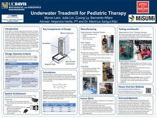
Key Components of Design
Belt Speed
(mph)
Roller Speed
(rad/s)
Roller Torque
(N m)
Power
(W)
0.1 1.85 1.61 2.98
0.5 9.26 1.61 14.91
1.0 18.53 1.61 29.83
Motor enclosure
Handlebar
Roller
Belt tension
mechanismSupport Plate
Acknowledgments
Project funding was provided by the UC Davis Clinical and
Translational Science Center (CTSC) and the Department of
Mechanical and Aerospace Engineering. In addition, Misumi
USA sponsored materials through their University Program.
Special thanks goes to Professor Michael Delwiche for helping
with the electrical system and Professor Barbara Linke for
letting our team use her lab space for our project development.
Finally, thanks to Kin Lam for transporting our project and
troubleshooting before our final testing at Easter Seals.
Calculations
The motor needs to provide enough power to drive the
treadmill belt with a child standing on it. The friction between
the roller and the belt is a function of the weight of the child
and the coefficient of friction between the PVC rollers and the
PVC treadmill belt.
𝐹𝑓𝑟𝑖𝑐𝑡𝑖𝑜𝑛 = 𝑊𝑐ℎ𝑖𝑙𝑑 ∗ 𝜇 𝑏𝑒𝑙𝑡
𝜏 𝑟𝑜𝑙𝑙𝑒𝑟 = 𝐹𝑓𝑟𝑖𝑐𝑡𝑖𝑜𝑛 ∗ 𝑟𝑟𝑜𝑙𝑙𝑒𝑟
𝑃 = 𝜏 𝑟𝑜𝑙𝑙𝑒𝑟 ∗ 𝜔 𝑟𝑜𝑙𝑙𝑒𝑟
Table 2 below shows the power required based on the desired
belt speed for a 50 pound child. A coefficient of friction of 0.3
between the PVC roller and the belt was used. The actual
power that the motor will be required to output will be greater
than what is shown in the table because the motor is not 100%
efficient and there will be power losses.
Table 2: Power required given the required speed.