SlideShare a Scribd company logo
1 of 107
Download to read offline
Final Report
Optimizing a Hydraulic Regenerative Braking System for a 20” Bicycle Wheel
The University of Michigan
ME 450: Design & Manufacturing III
Winter 2009
Team Members
Bryan D’Souza
Andrew Kneifel
Victor Singh
Matthew Williams
Section Instructor
Steven Skerlos
April 21, 2009
1
Executive Summary
With a growing concern of climate change and decreasing availability of fossil fuels, the U.S.
Environmental Protection Agency (EPA) has been researching hydraulic hybrid transportation
systems. For seven years, the EPA and ME450 students at The University of Michigan (U-M)
have collaborated on projects developing Hydraulic Regenerative Braking Systems (HRBS) for
bicycles. These systems conserve energy that is normally lost during friction braking. The bike’s
kinetic energy is used to drive hydraulic fluid into an accumulator via a pump, braking the
vehicle. This stored energy is later released to accelerate the bike forward.
This semester we have refined previous HRBS designs by optimizing the mechanical systems
and improving safety. A key goal for our team was to build a functioning prototype 20” wheel
that weighs less and has fewer moving parts than previous generations. Our team has made
minimal changes to the extant hydraulic system, as the parts have been well-researched and
recommended by our sponsor, David Swain of the EPA. Working with Mr. Swain, we created a
list of customer requirements for this project. Table 1 below lists many of our key engineering
specifications that were created to meet these requirements, as well as the final characteristics of
the prototype. Our four categories for engineering specifications are safety, cost, weight, and
functionality. Due to the conflicting nature of these specifications, it has been difficult to
improve many of the bike’s systems without adversely affecting others. Compromises have been
necessary in order to create a feasible design.
Table 1: Summary of key engineering specifications
Characteristic Target Prototype
Front wheel assembly weight ≤ 30 lbs 24.75 lbs
Bicycle load rating (rider weight) ≤ 160 lbs > 200 lbs
System pressure as limited by relief valve ≤ 4200 psi ≤ 4200 psi
Bicycle deceleration target 3.4 m/s2
– 3.6 m/s2
not available
Bicycle acceleration target 2.0 m/s2
– 2.5 m/s2
not available
Number of moving/rotating parts inside hub < 11 7
Prototype cost ≤ $1400 $1338
Many of the main hydraulic components have long acquisition lead times. To meet our goal of
having a functional prototype by the end of the term, we expedited concept generation and
selection so as to leave enough time to order and receive these parts. We created a detailed plan
for the semester based on expected task requirements as well as these lead times.
In reducing the weight of the prototype compared to previous designs, we have significantly
reduced the number of gears, replaced the bulky fiberglass hub support system with a lightweight
aluminum spoke system, and removed excess material from the internal support plate
(“superbracket”). These modification choices were made from a broad number of concepts,
based on a thorough analysis of the forces and torques required of each of the components. The
main engineering obstacles to implementing these design improvements have been dealing with
the nonstandard interface between metric and non-metric components, and determining the
routing of the hydraulic circuit.
2
Table of Contents
Executive Summary........................................................................................................................ 1 
1 Abstract........................................................................................................................................ 5 
2 Introduction.................................................................................................................................. 5 
2.1 Background and Motivation.................................................................................................. 5 
2.2 Project Description................................................................................................................ 6 
3 Information Search....................................................................................................................... 7 
3.1 Automotive Research and Applications................................................................................ 7 
3.2 Bicycle Research and Applications....................................................................................... 8 
3.3 Previous Bicycle Design Information ................................................................................... 9 
3.4 Future Research................................................................................................................... 10 
4 Project Requirements & Engineering Specifications................................................................. 10 
4.1 Customer Requirements...................................................................................................... 10 
4.2 Engineering Specifications.................................................................................................. 11 
5 Concept Generation ................................................................................................................... 13 
5.1 Functional Decomposition .................................................................................................. 13 
5.2 Hydraulics ........................................................................................................................... 14 
5.3 Powertrain & Packaging...................................................................................................... 15 
5.4 Hub...................................................................................................................................... 15 
5.5 Superbracket........................................................................................................................ 15 
5.6 User Interface and Controls................................................................................................. 15 
6 Concept Selection ...................................................................................................................... 16 
6.1 Hydraulics ........................................................................................................................... 16 
6.2 Powertrain ........................................................................................................................... 16 
6.3 Hub...................................................................................................................................... 16 
6.4 Superbracket........................................................................................................................ 17 
6.5 User Interface & Controls ................................................................................................... 17 
7 System Model ............................................................................................................................ 17 
7.1 Pump and Motor Gear Reductions...................................................................................... 20 
7.2 Motor and Pump Performance Curves................................................................................ 21 
7.3 Bike System......................................................................................................................... 22 
3
7.4 Hydraulic System................................................................................................................ 23 
7.5 Discussion of System Losses .............................................................................................. 24 
7.6 Transmission Tuning Analysis............................................................................................ 25 
8 Design of Selected Concept....................................................................................................... 26 
8.1 Parameter Analysis.............................................................................................................. 26 
8.1.1 Hydraulics..................................................................................................................... 26 
8.1.2 Powertrain..................................................................................................................... 27 
8.1.3 Hub ............................................................................................................................... 29 
8.1.4 Superbracket................................................................................................................. 33 
8.1.5 User Interface & Controls............................................................................................. 34 
8.2 Final Design ........................................................................................................................ 35 
8.2.1 Hydraulics..................................................................................................................... 35 
8.2.2 Powertrain..................................................................................................................... 36 
8.2.3 Hub ............................................................................................................................... 37 
8.2.4 Superbracket................................................................................................................. 38 
8.2.5 User Interface & Controls............................................................................................. 39 
8.3 Prototype Design................................................................................................................. 40 
8.4 Fabrication Plan................................................................................................................... 41 
8.4.1 Hydraulics..................................................................................................................... 41 
8.4.2 Powertrain..................................................................................................................... 42 
8.4.3 Hub ............................................................................................................................... 43 
8.4.4 Superbracket................................................................................................................. 46 
8.4.5 User Interface & Controls............................................................................................. 48 
8.5 Prototype Assembly ............................................................................................................ 49 
8.6 Validation Plan.................................................................................................................... 53 
9 Project Plan................................................................................................................................ 54 
9.1 Phase I: Project Background & Specifications ................................................................... 55 
9.2 Phase II: Concept Generation & Selection.......................................................................... 55 
9.3 Phase III: Final Design........................................................................................................ 55 
9.4 Phase IV: Alpha Prototype.................................................................................................. 55 
10 Recommendations.................................................................................................................... 56 
4
10.1 Motor/Pump Selection....................................................................................................... 56 
10.2 Clutch Selection ................................................................................................................ 56 
10.3 Hydraulic Manifold........................................................................................................... 56 
10.4 Superbracket stiffness analysis.......................................................................................... 56 
10.5 Work with experts............................................................................................................. 57 
10.6 Aggressive sourcing and manufacturing schedule............................................................ 57 
10.7 Accurate CAD model........................................................................................................ 57 
11 Conclusion ............................................................................................................................... 57 
12 References................................................................................................................................ 58 
13 Biographies .............................................................................................................................. 60 
13.1 Bryan D’Souza.................................................................................................................. 60 
13.2 Andrew Kneifel................................................................................................................. 60 
13.3 Victor Singh ...................................................................................................................... 60 
13.4 Matthew Williams............................................................................................................. 61 
14 Acknowledgements.................................................................................................................. 61 
Appendix A – QFD....................................................................................................................... 62 
Appendix B – Gantt Chart ............................................................................................................ 63 
Appendix C – Prototype Costs...................................................................................................... 64 
Appendix D – Bill of Materials .................................................................................................... 65 
Appendix E – Design Analysis Assignment................................................................................. 67 
Spoke Material Selection .......................................................................................................... 67 
Gear Material Selection............................................................................................................. 70 
Spoke Environmental Performance........................................................................................... 72 
Gear Environmental Performance............................................................................................. 74 
Spoke Manufacturing Process................................................................................................... 77 
Gear Manufacturing Process..................................................................................................... 77 
Appendix F – DesignSafe Report ................................................................................................. 78 
Appendix G – FMEA.................................................................................................................... 84 
Appendix H – CAD Drawings...................................................................................................... 86 
5
1 Abstract
The U.S. Environmental Protection Agency (EPA) is researching hydraulic hybrid transportation
systems in an effort to address the growing concerns about global climate change and insatiable
fossil fuel demands. Hydraulic hybrid vehicles use regenerative braking to store energy in
pressurized fluids. This energy is then released to assist in vehicle acceleration. For the past
seven years, ME450 students at The University of Michigan (U-M) have been developing
designs for hydraulic hybrid bicycle systems. This semester we refined the design of a hydraulic
hybrid system enclosed in a 20” bicycle wheel, with a focus on decreasing weight, improving
safety, and reducing the number of moving parts.
2 Introduction
This section outlines the origins of the hydraulic hybrid bicycle system concept at the EPA as
well as the driving force for its development. A brief outline of the project’s scope for the Winter
2009 semester of ME450 is also presented below.
2.1 Background and Motivation
Founded in 1970, the United States Environmental Protection Agency is a federal body tasked
with correcting environmental damage and establishing guidelines to help protect the natural
environment of the United States [1]. Research into clean energy, particularly for use in
transportation, is the focus of several of the EPA’s efforts [2]. In cooperation with Eaton
Corporation, United Parcel Service, Ford, International, and the U.S. Army, the EPA has
developed several hydraulic hybrid vehicles for the purposes of improving fuel economy and
reducing environmental impact [3].
The primary concept of hydraulic hybrid technology is to capture and utilize the energy that
would otherwise be lost during braking and use it to accelerate the vehicle. As the vehicle brakes,
a hydraulic pump connected to the drivetrain pumps hydraulic oil into the high-pressure
accumulators. During vehicle acceleration, the energy stored in the accumulators is released back
into the drivetrain, as the fluid flows through a hydraulic motor. This significantly lowers the
amount of fuel needed to accelerate back to normal operating speeds [3]. The result of this
regenerative braking is a marked improvement in fuel economy – a feature that is not just better
for the environment, but also reduces fuel costs for the owner. A diagram showing this hydraulic
regenerative braking system (HRBS) is shown in Figure 1 on page 6.
6
Figure 1: The hydraulic fluid’s path in an HRBS [4]
The use of bicycles for commuting reduces fossil fuel use, greenhouse gas emissions, roadway
congestion, and vehicle miles traveled while increasing the user’s physical health [5]. The EPA
has demonstrated 20-40 percent fuel economy improvements by installing HRBS on vehicles
with internal combustion engines [3]. The possibility of clean, efficient transportation with
hydraulic assistance bears exploration. The EPA has been working with U-M students on
hydraulic bicycle implementation since 2002, but the project has produced only one functional
product.
2.2 Project Description
The goal of this project is to develop a hydraulic regenerative braking system for a children’s 20”
bicycle. Due to the difficult nature of scaling down a hydraulic system, and the comparative ease
of scaling upwards, the intent of using a 20” bicycle is to analyze the weight, force, and torque
issues inherent to the HRBS on a small scale.
The EPA has been working on HRBS bicycles with ME450 students for the past seven years.
Previous ME450 teams have worked on fitting these systems in 26” and 20” bicycle wheels. The
primary focus of our work on the HRBS is refining the existing designs by improving safety,
reducing weight, ensuring functionality, and lowering cost. We are designing an HRBS for a 20”
wheel. Notably, one of the main goals is to reduce the device weight to 30 lbs without sacrificing
mechanical robustness or safe pressure containment. We plan to retain the majority of the
hydraulic components from past designs, as this technology has been well-researched and
documented by David Swain and previous teams. By focusing on reducing moving parts,
decreasing weight, and improving safety, we are further developing the understanding and
implementation of HRBS technology through the fabrication of a functional prototype.
7
3 Information Search
To gain a better understanding of hydraulic hybrid systems, our team surveyed a broad collection
of information including research papers, previous ME450 reports, and EPA resources. This
section of the report discusses the information we found regarding hydraulic hybrid vehicle
technology.
Hydraulic systems are used in a variety of applications such as machinery, braking systems, and
energy storage. They are often used because of their ability to transfer large forces and convert
kinetic energy into potential energy efficiently. To safely utilize this technology, many
precautions must be taken to prevent high-pressure systems from rupturing.
The EPA, U-M, and companies such as Eaton and Ford have been developing hydraulic hybrid
systems for transportation applications including cars, trucks, and bicycles. Hydraulic hybrid
bicycle technology has been pioneered through a partnership between the EPA and U-M. For
seven years, ME450 students at U-M have been researching, designing, and building hydraulic
hybrid bicycle systems using HRBS. These systems require improvements in safety,
functionality, and performance.
3.1 Automotive Research and Applications
The EPA has been developing hydraulic hybrid systems for three main automotive sectors:
conventional vehicles, urban delivery trucks, and large SUVs and pickup trucks [3]. Each of
these three sectors utilizes parallel and series hydraulic hybrid systems.
Parallel hydraulic hybrid systems utilize HRBS to pump incompressible hydraulic fluid into
high-pressure accumulators. Much of the energy that is lost through conventional braking
systems is recovered through this technique. This energy is then released by directing the
pressurized fluid through a hydraulic motor. This hydraulic motor powers the car during
acceleration. These systems are ideal for vehicles that operate under frequent stop-and-go
driving. Eaton uses parallel hybrid technology in its Hydraulic Launch Assist™ (HLA®) system
designed for refuse trucks and buses [6]. A computer model of the HLA® system can be seen in
Figure 2 on page 8.
8
Figure 2: Computer model of Eaton Corporation’s HLA® system for a refuse truck [6]
Series hydraulic hybrid systems replace the conventional drivetrain with a hydraulic drivetrain
[3]. The EPA applied this technology to a Ford Expedition. In this setup a pump powered by an
internal combustion engine is used to force fluid through a hydraulic motor. The motor uses the
energy stored in the fluid to power the vehicle. Along with a hydraulic drivetrain, series vehicles
use HRBS to recover energy lost during braking. The regenerative system is directly plumbed
with the hydraulic drivetrain and helps the vehicle accelerate. The EPA estimates that full
hydraulic drive vehicles could result in 30-40 percent improvements in combined city/highway
fuel economy and lower emissions [3]. The EPA-modified Ford Expedition obtained a combined
city/highway fuel economy rating of 32 miles per gallon (mpg) compared to its standard 14 mpg
rating [7, 8].
The EPA has teamed up with UPS, Eaton, International, and the U.S. Army to develop the next
generation of urban delivery vehicles using hydraulic hybrid technology. UPS is currently the
main customer of these vehicles and has provided the EPA with delivery trucks to retrofit. Using
hydraulic hybrid technology, it has been shown that the fuel economy of these trucks can be
increased from 10 mpg to 18 mpg. Delivery trucks are strong candidates for hybrid systems due
to their frequent stops.
3.2 Bicycle Research and Applications
Different forms of hybrid bicycles have been used for years, including mopeds and electric
bicycles. Most of these systems are powered by gasoline or batteries. Some electric bicycles use
regenerative braking, but this feature is not common. ME450 students at U-M have been
developing hydraulic hybrid bicycles using regenerative braking as the energy source. This
system is unique because it conserves kinetic energy by converting it to mechanical potential
energy rather than refilling or recharging an energy source.
In December 2006 a team of engineers from U-M and the EPA filed for a patent on hydraulic
regenerative braking for a vehicle [9]. This patent is based on the functional hydraulic hybrid
bicycle designed and built through ME450 in Fall 2005 and a research project in 2006. This bike
has been important for benchmarking purposes. The HRBS was enclosed in a modified 26”
9
bicycle wheel. Testing this bike provided information on optimal acceleration and deceleration
speeds, accumulator pressures, and hydraulic component size. In Winter 2007, an ME450 team
created a redesign of the internal components of this bike. The final product was not a functional
bike, but rather a model that demonstrated the process of hydraulic regenerative braking.
Beginning in the Winter 2008 term, ME450 projects regarding HRBS began focusing on
implementing a regenerative braking system into a 20” bike wheel. This is a standard wheel size
for kids’ bikes. By shifting research towards smaller wheels, the goals were to lighten and refine
the system. The 20” wheel containing the hydraulic hybrid system currently weighs about 70 lbs
[10, 11]. As of the date of this report’s publishing, the system is not yet operational.
In 2005 Parker-Hannifin Corporation began a design competition called the Parker Chainless
Challenge [12]. For this contest, students design bicycles powered using hydraulic pumps and
motors rather than chains. These bikes are series hydraulic systems. So far no team has entered a
bicycle with regenerative braking. Students at U-M are working with the EPA to develop a
hydraulic drive in parallel to an HRBS. U-M’s research for this design challenge began in 2007
as an ME450 project.
3.3 Previous Bicycle Design Information
ME450 project teams have created numerous HRBS bicycle designs. The most notable work has
been accomplished during the past four years. The first functional HRBS bicycle was finished in
2006 for a 26” wheel. This system utilized a single gear reduction between the motor/pump and a
large gear rigidly connected to the wheel hub. This system did not have any method to disengage
the gears from rotating during operation, meaning that while a rider was pedaling the bike, he
was also pumping fluid through the hydraulic loop. This increased the pedaling resistance and
decreased the bike’s efficiency. The hubs on this bike were made of carbon fiber and were
connected to a custom machined aluminum rim. Both the covers and the rim were quite heavy.
The custom rim decreased serviceability and increased cost. The thicknesses of the material used
to make the superbracket (4mm) and front bike fork (0.125”) resulted in heavy structural
components.
In 2007, two teams refined the HRBS for manufacturability. A physical system was built;
however, this system was not attached to a bike. The system that was built is housed within a
display case and connected to a hand-powered hydraulic pump. Overall, the components used
were comparable to those used in 2006.
Teams in 2008 further developed the design by incorporating an HRBS into 20” bicycle wheel.
Using a 20” wheel was chosen to constrain the design and motivate innovation. This design
contained a few notable improvements, but also opened the door for our team to make more
changes. The first main improvement was creating a system that no longer used bevel gears.
Earlier designs had used bevel gears to redirect rotation. The bevel gears were difficult to align
which decreased overall efficiency. In this design, the motor and pump were rotated 90° and only
spur gears were used to transmit the rotational energy. The motors and pumps used in designs
prior to 2008 were too large, so in 2008 smaller motors and pumps were selected for the system.
Additionally clutches were installed to disengage the pump and motor from rotating when
neither the braking nor the launch system was engaged.
10
These improvements were beneficial, but there is still much room for improvement. The 2008
bike is not yet functional. Work is currently being done by two former ME450 students to
complete the bike, improve the design, and test its performance. The hubs used on the 2008
bicycle were made of ½” thick fiberglass. Combined, the two hubs weighed about 40 lbs. The
gears used on this system were ½” thick solid steel weighing a total of 12 lbs. While these gears
were robust, they were overdesigned for the number of cycles seen in this system. The front fork
and superbracket were also unnecessarily heavy components. The superbracket was made of 4
mm thick 1018 steel and the front fork was made of tubes with 0.125” wall thickness. Excluding
the fork, these components resulted in an HRBS weighing approximately 70 lbs.
The 2008 system also posed problems for users effectively operating and maintaining it. The
switches to engage the braking and launching systems were mounted on the bike frame directly
in front of the seat tube. This setup would have required the rider to let go of the handlebars to
engage and disengage the system. The bike was also difficult to service, as most of the
components were welded together. There was an additional safety concern posed by the lack of a
pressure relief device on the system. This could lead to unsafe operation, as the hydraulic
components were only rated to 4000 psi. While much work has been done over the last seven
years, more work is needed to effectively implement a hydraulic regenerative braking system on
a bicycle.
3.4 Future Research
In order to further develop a hydraulic hybrid system, more research will need to be completed.
The main topics of research this term focused on gear design, hydraulic component sizing, hub
strength, and superbracket stiffness. In order to decrease the overall system weight, we
investigated gear layouts and strength. Hydraulic component sizing was important in reducing
the number and size of fittings. We analyzed the hub strength using FEA to ensure our design is
strong enough to safely support a rider. More research into superbracket stiffness will be
necessary to prevent gear disengagement and component vibration.
4 Project Requirements & Engineering Specifications
To outline the specifications for this project, we began by defining our customer requirements.
We then translated these requirements into engineering specifications. This section of the report
details these requirements and the resulting specifications.
4.1 Customer Requirements
The customer requirements for this term, as outlined by our sponsor David Swain, are
continuations of the past two semesters with an added emphasis on three major underlying
themes–safety, performance, and cost– to guide the formation of our engineering specifications.
Table 1 on page 11 shows a listing of our customer’s requirements, as grouped by the three
major themes and their relative importance in each.
11
Table 1: Customer requirements categorized and listed by importance
Relative
Importance
Safety Performance Cost
High User Safe Lightweight
Inexpensive Manufacturing
Processes
Natural Braking Rate Reliable
Fastenable to a Stock
Bicycle
Easy to Use Efficient Material Costs
Easy to Service
Sufficient Launch
Speed
low
4.2 Engineering Specifications
When translating the customer requirements into engineering specifications, cost and safety
translated directly. However, performance split into weight and functionality, as we find both
categories of high enough importance to be separate. The resultant engineering specifications are
described in the following list. The interactions between these specifications and their correlation
to the customer requirements can be seen on our Quality Function Deployment (QFD) in
Appendix A on page 62.
Note: Items in italics are integral to a complete design solution, but are not slated for
implementation during the W09 timeframe.
1. Safety
a. Hydraulic System
i. Design shall incorporate pressure relief valve and line to dump high-
pressure fluid to the low-pressure side in the event of overpressure (excess
of 4200 psi).
ii. High-pressure components and lines shall be sufficiently isolated from the
user so as to prevent health and safety hazards in the event of a leak or
rupture at 4200 psi.
iii. High-pressure components and fittings shall be properly labeled for safety
purposes.
iv. Design shall provide a method by which the user may release the system
pressure without accelerating the device.
b. Power Transmission System
i. Gears shall be sized to appropriately handle the torques/forces imposed
upon them, without deforming or breaking themselves or the components
to which they are mounted.
ii. Moving/rotating components, especially those with teeth, shall be
sufficiently isolated from the user so as to prevent mechanical safety
hazards.
iii. Moving/rotating components that present a mechanical hazard shall be
properly labeled for safety purposes.
12
c. Electrical System
i. Voltage and current sources shall be kept as far from the user as possible,
such that the only interaction with the electrical system under normal
circumstances is through use of well-insulated switches/toggles; in the
event of an electrical system failure, the maximum exposure to electricity
would result in less than 4 mA entering user.
ii. No user interface devices such as switches/toggles shall be mounted in
such a manner as to cause unsafe operation of the device.
iii. Electrical components that impose dangerous voltage/current levels during
normal operation, or could impose dangerous voltage/current levels in the
event of an electrical malfunction, shall be properly labeled for safety
purposes.
d. General Safety
i. Mechanical connection between front tire and front fork, regardless of
modifications to original bicycle design, shall be robust enough to support
a rider weighing 160 lbs based on the weight of a 95th
percentile 14-year-
old boy [13].
ii. Device deceleration should be limited to 3.6 m/s2
to prevent user from
losing control during braking.
iii. Device should retain stock rim brakes on the rear wheel to allow for
braking in the event of a complete front-wheel system failure.
iv. Brake controls should be integrated in such a way that conventional
friction braking may be imposed by actuating the RBS control with more
force (e.g. squeezing harder in the event of the RBS failing to decelerate
the bike properly).
2. Weight
a. Target
i. Total front wheel assembly, including tire and rim, should weigh not more
than 30 lbs.
3. Functionality
a. Pedaling
i. Impediment to pedaling when the HRBS is disengaged should be
minimized through use of clutches or other disengagement components.
b. Braking
i. Device should respond within 500ms to call for braking.
ii. Braking should be swift, but not violent; target range is 3.4 – 3.6 m/s2
based on testing completed on the functional 2006 bike.
iii. Upon full stop, device should refrain from accelerating backwards (the
system must utilize a check valve to prevent the release of high-pressure
flow from the accumulator).
c. Launch
i. Device should respond within 500ms to call for launch.
ii. Launch should be swift, but not rapid enough for the front tire to lose grip;
target range is 2.0 – 2.5 m/s2
based on testing completed on the functional
2006 bike.
13
iii. Call for launch when device is already in motion should not damage or
bind clutch, which could cause violent braking.
d. Servicing
i. Design should allow the typical user to perform standard maintenance
operations, including replacing a worn/damaged inner tube.
ii. Device should be able to be disassembled (i.e. no major components
permanently connected).
iii. Tire filling should not require disassembly.
4. Cost
a. Target
i. Total expended cost of the prototype (not including labor or components
provided by sponsor) shall be not more than $1400.
5. Interactions Between Specifications
a. Conflicting Specifications
i. The weight target of 30 lbs (2.a.i) directly opposes several safety targets
(1.a.i-ii, 1.b.i-ii, 1.d.i). Ensuring device safety by using larger, more-robust
components will increase the total weight of the device.
ii. The cost target of $1200 (4.a.i) directly or indirectly opposes several other
targets (1.a.i, 1.a.iv, 1.b.i, 1.d.i, 1.d.iv, 2.a.i, 3.a.i). Components necessary
to maximize safety, robustness, desirable operation, and weight reduction
tend to be more costly.
b. Consistent specifications
i. Several safety targets (1.a.ii, 1.b.ii, 1.c.i) may be met simultaneously
through proper device shielding.
5 Concept Generation
To effectively generate a broad collection of concepts, we began by decomposing the main
subsystems of the HRBS. After breaking down the subsystems, we listed the main components
of each. Each team member then created a list of concepts for each of the components. We then
met as a team to build on one another’s ideas and we created a master concept list.
5.1 Functional Decomposition
Based on the unique history and relative complexity of our project, we followed a slightly
different concept generation process than most teams. We began by decomposing the bicycle
HRBS into five functional subsystems. These subsystems are hydraulics, powertrain, hub,
superbracket, and user interface. Each of these subsystems contained at a minimum two major
components. Figure 3 is a functional decomposition tree showing which components fall under
which subsystem.
14
Figure 3: Functional decomposition tree outlining main components of each subsystem
After completing the functional decomposition, we generated concepts for each of the subsystem
components. By individually creating concepts and analyzing them as a team, we were able to
attack each design problem from multiple angles.
5.2 Hydraulics
The subsystem most refined by previous teams is hydraulics. This is also the subsystem with the
longest lead-time items. As a result, many of our hydraulic components—including the pump,
motor, high pressure accumulator, tubing & fittings, and low pressure reservoir—will remain the
same as those specified by previous teams.
In addition to the systems used on previous generations, it is important to include a pressure
relief system to prevent over-pressurizing the system. This can be achieved by including a
variable pressure relief valve or a burst disc.
The valves category is made up of a check valve preventing high pressure flow from entering the
pump and a directional valve to start and stop the launch process. There are various types of
check valves that respond better to different pressures. The directional valve could either be a
two-way or a three-way electronic valve. There are different types of each of these valves that
15
vary in their sealing method. Poppet valves seal quite well, leaking only a few drops per minute;
spool valves can leak multiple milliliters per minute.
5.3 Powertrain & Packaging
Powertrain decomposes into only two component categories, but it is very complicated due to the
packaging constraints of a 20” bicycle wheel. In the past, the mechanical reduction was created
using steel spur gears. We generated many concepts including plastic gears, phenolic gears,
sprockets & chain, cogged belts, cables & pulleys, and friction rollers like those used to launch
roller coasters.
The second powertrain category is clutch mechanisms. A system is needed to disengage the
pump and motor from the rotating hub when braking and launching are not engaged. Concepts to
complete this task included electromechanical clutches (benchmark), mechanical clutches, roller
clutches, and a custom clutch utilizing a linear actuator.
5.4 Hub
The hub’s main roles on the bike are to support the rim, to interface with the mechanical
reduction, and to enclose the system’s moving components. This hub rotates around the bike’s
axle, which is stationary. Previous teams have created hubs made of carbon fiber and fiberglass.
We included these in our concept list as well as aluminum sheet metal, vacuum formed plastic,
and spokes with a thin cover. We developed another concept by combining the spoke and
vacuum form designs. In this design a rigid skeletal structure would be used to support the
bicycle and a thin plastic cover would enclose the system.
5.5 Superbracket
The superbracket subsystem is made up of the superbracket and the bike’s axle. These
components are rigidly connected together. The hub rotates on the axle and electric wiring exits
the hub through the center of the axle. Designing the superbracket is a material selection and
thickness optimization problem. The bracket needs to support the hydraulic and mechanical
components and prevent the pump and motor’s output/input shafts from being loaded radially.
To meet these criteria we created a list of potential materials, including steel, aluminum,
fiberglass, tooling board, wood, carbon fiber, and plastic. Along with material selection we have
discussed methods of increasing the bracket’s stiffness by using dimple dies, adding gussets, and
adding angle iron reinforcements.
5.6 User Interface and Controls
Previous designs incorporated a switchbox for controlling the brake and launch functions. This
box was mounted on the frame of the bike directly in front of the seat. While functional, this
forces the rider to let go of the handlebars with at least one hand to activate either system. In the
event of a system braking failure, the rider would have to quickly adjust his hand position to
activate the hand brake on the handlebar. One concept that could potentially solve this problem is
to integrate the switch and the preexisting hand brake. This could be done by splicing a toggle
switch into the cable. A light squeeze on the hand brake could activate the HRBS, while a hard
squeeze would be enough to engage the friction brakes. Another option, provided that the bike is
equipped with front and rear brakes, is to leave the rear hand brake unmodified and splice a
toggle switch into the front hand brake cable. The launch activation could potentially be
switched via a toggle switch mounted on the handlebars, or a pushbutton mounted on the
16
handlebars. If two switches are wired in parallel, there is the advantage that both switches must
be activated for the launch to be triggered – this could be beneficial from a safety standpoint.
6 Concept Selection
The concepts described above are suitable for general applications. For example, a belt & pulley
power transmission is able to transfer torque and rotational speed. However, in our small and
lightweight bicycle, such a mechanism is unreasonable due to the added difficulty in developing
and sustaining tension. Because of this, reasonable feasibility was the primary criterion for all of
our concept selections.
Next, we compared each reasonable concept to a benchmark. In our case, the benchmark was the
corresponding sub-assembly of the previous bicycle (Fall 2008). All concepts that were inferior
to the benchmark were discarded because our design needs to improve on the previous iteration.
The criteria used for comparing concepts included design characteristics, manufacturing, weight,
safety, and cost.
6.1 Hydraulics
For the hydraulic subsystem, the components remain relatively unchanged except for the 2-way
valve, filter, and relief valve. The new 2-way valve has the same functionality and size as the
benchmark, but leaks at a much lower rate (5 drops per minute vs. 5 ml per minute). The new
filter is rated for particles as small as 2 microns, and is able to withstand pressures of up to 6000
psi (the previous design was only rated to 1500 psi). The addition of a relief valve will allow
fluid pressurized above the recommended accumulator limit of 4000 psi to be dumped safely into
the low pressure accumulator. No such mechanism was present on the benchmark subsystem.
6.2 Powertrain
For the powertrain subsystem, we use drilled-out steel spur gears. These are much lighter than
the current solid steel gears and offer similar strength properties – the lightening holes are
strategically placed so as to remove excess material without sacrificing structural integrity.
To disengage the pump from the rotating hub, we plan to use the same 24V electromechanical
clutch used by previous teams. This clutch was selected because it is relatively small in size and
can transmit a larger amount of torque than comparably sized clutches.
We will use a Timken one-way clutch bearing to disengage the motor. When the motor is not
engaged, it is disconnected from the gears. This clutch bearing requires no electrical power and
weighs only 1/100th
of a second clutch. Using the clutch bearing adds a precision machining
process to create the proper press fit.
6.3 Hub
The hub subsystem will not be made out of the benchmark material (thick fiberglass), but will be
comprised of outer metal spokes covered by a vacuum formed ABS plastic cover. This
substantially reduces the weight of the bicycle wheel and allow for quicker, more precise
fabrication. A mold for the hub cover will be created out of Renboard using a CNC router. The
vacuum forming will be done in the Art and Architecture woodshop.
17
6.4 Superbracket
The superbracket will be made from a thin stainless steel plate with strategically placed
reinforcements and lightening pockets. The circular envelope of the rim will be similar, but more
pockets and unnecessary material will be cut out of the plate for significant weight savings. We
will use thin angle iron to increase the rigidity while maintaining the weight reduction. The
stiffness of the superbracket should not be compromised as the previous iteration was
overdesigned.
6.5 User Interface & Controls
The user interface will be reworked from the current setup of a box mounted between the rider’s
legs. A handlebar mounted system will utilize two pushbutton switches that must be engaged
simultaneously to activate the launch process. Instead of the front hand brake connecting to
calipers on the front wheel, it will connect to a momentary switch that will activate the
regenerative braking process. This lends itself to improved stability for the rider, as s/he does not
have to remove a hand from the handlebars to operate either of the systems. Wires will run
through the hollow shaft of the handlebars so that charged components are kept away from the
user. Also, for additional safety, a lock and key setup will prevent unauthorized users from
engaging any of the operations of the bicycle involving stored energy.
7 System Model
One of our goals this semester was to more rigorously define the theoretical model of the HRBS
through the use of computer simulation (Simulink), something that has not been attempted in
previous generations. Though we have used it primarily to evaluate performance characteristics
and design selection of the HRBS, we realize that this model will provide a valuable source of
information to existing research as well as to future works.
The theoretical model is constructed around the pump and motor transmission, from which the
other subsystems developed overtime. The architecture of the theoretical model is shown in
Figure 4 with the complete model shown in Figure 5 on page 18. All variables used in the model
are listed in Table 2 on page 19.
Figure 4: Architecture of theoretical model
18
Figure 5: Complete HRBS model
19
Table 2: List of all variables used in theoretical model
Variable Subsystem Description
ω1 Pump/Motor Transmission
& Performance Curves
Angular speed of pump or motor shaft and gear
ω2 Pump/Motor Transmission Angular speed of 2nd
gear on first reduction
ω3 Pump/Motor Transmission Angular speed of clutched gear
ω4 Pump/Motor Transmission Angular speed of main gear and front wheel
ω5 Pump/Motor Transmission Angular speed of meshed 5th
gear from other transmission
R1 Pump/Motor Transmission Pitch radius of pump or motor gear
R2 Pump/Motor Transmission Pitch radius of 2nd
gear on first reduction
R3 Pump/Motor Transmission Pitch radius of clutched gear
R4 Pump/Motor Transmission Pitch radius of main gear
R5 Pump/Motor Transmission Pitch radius of meshed 5th
gear from other transmission
I1 Pump/Motor Transmission Rotational inertia of pump or motor gear
I2 Pump/Motor Transmission Rotational inertia of 2nd
gear on first reduction
I3 Pump/Motor Transmission Rotational inertia of clutched gear
I4 Pump/Motor Transmission Rotational inertia of main gear
I5 Pump/Motor Transmission Rotational inertia of 5th
gear from other transmission
Tin Pump/Motor Transmission
& Performance Curves
Torque applied by motor and pump shaft to transmission
Tout Pump/Motor Transmission Torque applied to wheels
Ts Pump/Motor Transmission Torque applied to clutched shaft
F12 Pump/Motor Transmission Tangential force between motor or pump gear to 2nd
gear on
first reduction
F34 Pump/Motor Transmission Tangential force between main gear and 1st
gear on 2nd
reduction
P Performance Curves Pressure on high side of pump or motor
Iw Bike System Inertia of front (and rear) wheel
M Bike System Total mass of bike (w/ rider)
Rw Bike System Radius of the front (and rear) wheel
a Bike System Acceleration of the bike
PnR Hydraulic System Precharge pressure of hydraulic accumulator
VnR Hydraulic System Volume of nitrogen gas for empty accumulator
Pg Hydraulic System Instantaneous nitrogen gas pressure
Pc Hydraulic System Charge Pressure (for motor system)
Vg Hydraulic System Instantaneous nitrogen gas volume
Vfo Hydraulic System Initial fluid volume
Vf Hydraulic System Instantaneous fluid volume
Q Hydraulic System Flow rate of fluid into the accumulator
20
7.1 Pump and Motor Gear Reductions
Figure 6 shows the geometry of the pump or motor transmission model (since both transmissions
are the same). The transmission is a double reduction system (1 to 2 and 3 to 4) that amplifies the
torque transmitted to the front wheel in two stages.
Figure 6: Geometry and loadings of transmission system
Using free body diagrams, the corresponding dynamics of each gear is determined in Equations
1-4.
1
1
1
12 ω

I
R
F
Tin =
− (1)
2
2
2
12 ω
=
− 
I
T
R
F s (2)
( ) 3
2
3
34 ω
+
=
− 
s
s I
I
R
F
T (3)
4
2
5
4
5
4
4
34 ω
⎟
⎟
⎠
⎞
⎜
⎜
⎝
⎛
⎟
⎟
⎠
⎞
⎜
⎜
⎝
⎛
+
=
− 
R
R
I
I
T
R
F out (4)
Although we could have largely simplified the above equations by algebraically combining them
together, we chose not to in order to create separate subsystems for each gear. By doing this, we
have the ability to incorporate additional information (frictional losses of tooth grinding for
example) more efficiently if the need arises. Notice the inclusion of the 5th
gear in the above
equations and Figure 6. This is the satellite gear of the transmission not in operation. Though the
two transmissions are independent, this satellite gear is meshed and will always rotate when
either transmission is active. Alongside the dynamic analysis, a kinematic analysis reveals the
mechanical reduction of the system, as shown in Equation 5.
4
3
4
1
2
3
1
2
2
1
2
1 ω
=
ω
=
ω
=
ω
R
R
R
R
R
R
R
R
(5)
Utilizing Equations 1-5, we formed the transmission model for the motor and pump as shown in
Figure 7.
21
Figure 7: Motor (or Pump) transmission model
7.2 Motor and Pump Performance Curves
The motor and pump generates unique torques based on pressure and rotational speed.
Fortunately, the manufacturer of the pump and motor, Marzocchi, provides steady-state
performance curves [14] that trace their behavior for various operating points (see Figure 8).
Thus by mapping these performance curves, we could obtain the “plants” of the motor and
pump.
Figure 8: Motor and pump performance curves [14]
22
While a look-up table could have represented these curves, the operating pressure of our system
is above the values shown on the graphs in Figure 8. This meant most of the data would have to
be extrapolated and thus, a curve fit was considered. Noticing that the torque on the motor and
pump shafts is a strong function of pressure and a weak function of speed, the curve fit was
chosen by assuming that torque varied strongly with respect to pressure. The variation due to
speed was assumed to be a percentage change from the average torque at the constant baseline
pressure curve. The baseline pressure curve is the constant pressure line (on the performance
curves) from which the curve fits are extrapolated. The selection of this baseline is chosen such
that the extrapolated curve fits match as closely as possible to the actual performance curve data.
The speed variation was modeled as a quadratic function due to its consistency with the shape of
the performance curves. The generic curve fit is shown in Equation 6.
( ) ( )( )
eP
d
eP
d
c
b
a
P
T
BASE
in +
+
+
ω
+
ω
=
ω 1
2
1
, (6)
Here, ω is the angular speed of the motor/pump shaft (in rpm), P is the pressure on the high side
of the pump/motor (in bars), PBASE is the baseline pressure, and the variables {a, b, c, d, e} are fit
parameters. The fit parameters for both the motor and pump are shown in Table 3. The baseline
pressures were chosen such that the extrapolated curves matched as closely as possible to the
actual performance curves.
Table 3: Curve fit parameters for motor and pump
Motor Pump
PBASE 230 Bar 190 Bar
a* 1.400(10)-8
2.571(10)-8
b* -3.000(10)-5
-5.286(10)-5
c 2.216 2.260
d 0.2000 0.1219
e 0.01748 0.01130
* These parameters become extremely significant for
pump and motor speeds exceeding 4000 rpm.
7.3 Bike System
The analysis of the bike system was conducted using the free body diagram (FBD) in Figure 9,
from which the governing equations of the bike were determined (Equation 7).
23
Figure 9: FBD of bike
( )
w
w
w
out
R
a
MR
I
T
2
2 +
= (7)
It is important to note that the FBD analysis assumes rolling without slip, that is, the bike does
not skid during operation. Though this might be added later to validate the system model, it has
not been included since rolling without slip generates the greatest loadings, making them useful
for designing against failure. Also, since the front wheel is rigidly attached to the fourth gear of
the transmission, its angular speed is ω4. The model of the bike system is shown in Figure 10.
Figure 10: Bike system model
7.4 Hydraulic System
The hydraulic accumulator was modeled under the assumption that the nitrogen gas inside the
accumulator behaved isothermally. This is a reasonable assumption, as there shouldn’t be
significant temperature variations in the accumulator during operation. Utilizing conservation
laws, we determined the fluid and gas behavior of the fluid during operation (Equations 8-11).
Definitions of the variables used in these equations are found in Table 2 on page 19.
nR
nR
g
g V
P
C
V
P =
= (8)
f
nR
g V
V
V −
= (9)
∫
=
−
t
fo
f Qdt
V
V
0
(10)
24
nR
c
nR
fo V
P
P
V ⎟
⎟
⎠
⎞
⎜
⎜
⎝
⎛
−
= 1 (11)
The flow rate through the system is dependent on the displacement of the pump and motor
(assuming no energy losses in the pipes). Conveniently for us, Marzocchi also included flow rate
curves [14] with the performance curves. By mapping these curves (Figure 11), we found a
method of relating angular speed of the pump and motor to the flow rate. We chose a linear
curve fit for the flows. Here Q is the flow rate (L/min) and ω is the angular speed of the
pump/motor shaft (rpm). The corresponding fit parameter for both the motor and pump is shown
in Table 4.
ω
= a
Q (12)
Figure 11: Pump and motor flow curves
Table 4: Fit parameters for pump and motor flow rates
Motor Pump
a 0.00051 0.000635
7.5 Discussion of System Losses
System losses are important to discuss since they directly impact the validity of the system
model. Table 5 documents losses that have not been taken into account in each subsystem.
25
Table 5: Losses not modeled in the theoretical model
Subsystem Losses not modeled
Pump/Motor Transmission - Frictional losses and stored deformation energy of
meshed gear teeth
- Frictional losses in both clutches
- Frictional losses in all bearings
Performance Curves - Information uncertainty associated with back
calculating transient behavior from steady-state
Bike System - Frictional losses in all bearings
- Air drag
- Vibration of components
Hydraulic System - Entrance/Exit effects at small openings (valves,
pump, motor, accumulator, fittings)
- Air pockets and or instantaneous cavitations due
to motor/pump activity (model assumes fluid is
continuous and is present at all times in the lines)
- Heat and viscous losses in lines and hydraulic
accumulator.
7.6 Transmission Tuning Analysis
With an automobile, one must tune the transmission to obtain the highest efficiency from the
engine. The HRBS is no different. Utilizing the model, we tested different gear reductions of the
transmission to tune the system. The observed behavior of the system is documented in Table 6
for higher and lower reductions.
Table 6: System behavior for variations in transmission reduction
Reduction
Changes
Pump System Behavior Motor System Behavior
Higher
Reductions
- Lower final charge pressure - Slightly higher final speed
- Larger pump shaft speed - Larger motor shaft speed
- Larger deceleration - Larger acceleration
- Larger loadings on gears - Larger loadings on gears
Lower
Reductions
- Larger final charge pressure - Slightly lower final speed
- Lower pump shaft speed - Lower motor shaft speed
- Lower deceleration - Lower acceleration
- Lower loadings on gears - Lower loadings on gears
Based on the information presented in Table 6, we can argue that to maximize performance we
need to have as low a gear reduction as possible on the pump system (to acquire the largest
accumulator pressure) and to have the highest gear reduction as possible on the motor system to
26
take advantage of the higher final speed. However, there are limitations. For one, the high
accumulator pressure is limited to the design constraint of 4000 psi. This limited how low of a
reduction we could go on the pump side. Another constraint is that the maximum operating speed
of the pump and motor is 7000 rpm. This places an upper limit on possible gear reductions for
our HRBS. Further complicating the matter is the fact that our maximum acceleration and
decelerations levels are limited to those levels comfortable to a rider. These were previously
determined by our sponsor David Swain and are listed in the engineering specifications.
Testing stock gear sizes, we determined that a gear reduction of 17.5:1 for the both the pump and
motor transmission satisfied all design constraints (see Table 7). We chose to use the same
reduction for both the pump and motor to reduce the number of machining operations required
for different gear geometries. Although we sacrifice some performance on the motor side (a
slightly lower final speed), it does not outweigh the benefits of simpler machining schedules as
well as reduced loadings on the transmission components.
Table 7: Final gear sizes (pitch diameters) for transmission systems
Pump Gear Reduction
To
Wheel
Motor Gear Reduction
G1 G2 G3 G4 G3 G2 G1
1” 3.5” 1” 5” 1” 3.5” 1”
Final Pump
Reduction
17.5:1
Final Motor
Reduction
17.5:1
8 Design of Selected Concept
Our system model created load, speed, and pressure information for our system. From this
information and our component restrictions we created our final design. This section of the
report outlines our final design and an analysis of it including such parameters as shape, material,
and dimensions.
8.1 Parameter Analysis
Throughout our design process we have analyzed concepts for performance. This section of the
report documents these processes as they pertain to each subsystem of the HRBS. The selection
of purchased and custom parts is described.
8.1.1 Hydraulics
For safety purposes, the high-pressure side of the hydraulic system has been designed to
withstand pressures of 6000 psi, even though the maximum expected system pressure is 4000
psi. Due to material considerations, this effectively excludes the use of brass fittings and
components; while brass is commonly used in low-pressure systems, it is not strong enough to
safely manage 6000 psi. Likewise, most aluminum fittings are not rated for this high of
pressures. This leaves steel and stainless steel–the latter being preferred for its corrosion
resistance.
The gear pump and gear motor are manufactured by Marzocchi. Since they are 12-week lead-
time items, there was only one parameter to decide: use the pump and motor available through
27
(and preferred by) our sponsor or order a new pump and motor with the knowledge that neither
would arrive before the end of the semester. Since the W08 team had a significant problem with
the Marzocchi lead time, we used the components we had on-hand.
Impurities in the hydraulic fluid will cause accelerated wear on the pump and motor, and will
prevent the poppet valves from seating properly. According to Norman Filter Company, LLC,
the most damaging contaminants in hydraulic systems are in the range of 3-20 microns [15]. As
such, we have chosen a 2-micron stainless steel filter manufactured by Swagelok. Since the filter
is to be placed on the high-pressure side of the system, it is rated for pressures up to 6000 psi. If
the filter was placed on the low-pressure side of the system, it would present a restriction to flow
resulting in possible cavitation or vacuum generation inside the pump, both of which are
damaging. Placing the filter directly after the pump maximizes the number of components
receiving freshly-filtered fluid.
To prevent backflow into the pump, the system utilizes a check valve after the filter. The check
valve also keeps the fluid from back-flushing contaminants out of the filter and into the system.
To reduce the resistance to opening, the crack pressure was chosen to be 1 psi. Manufactured by
Swagelok, the check valve is made of stainless steel and is rated to 6000 psi.
The hydraulic accumulator is another component made available by our sponsor; the only
parameter to decide was the nitrogen pre-charge pressure, which was selected to be 2200 psi
based on data collected in previous semesters. This pre-charge is lower than previous generations
so that system functionality may be tested under reduced loading conditions.
The system control valve had several options. Previous designs have used three-way spool
valves, which leak at a rate of multiple mL/min. These valves are also available in poppet valve
form, a style that leaks at a rate of drops/min. The two-way electronically-actuated poppet valve
was chosen because it is smaller and leaks less than previous selections. The steel valve housing
option was chosen over the aluminum option as the steel housing is rated to 6000 psi, whereas
the aluminum housing is rated to 3300 psi. The main drawback of this selection is the larger
weight of steel vs. aluminum.
The requirements for the low-pressure reservoir are markedly less severe than the requirements
for high-side components. The reservoir must be large enough to handle 150 mL of hydraulic
fluid while not monopolizing too much space in the superbracket envelope. The material must
also be nonreactive with hydraulic fluid. We chose a polyethylene terephthalate (PET) honey
bottle, mainly due to size and cost considerations.
8.1.2 Powertrain
Once the gear reductions were optimized using our Simulink model, we analyzed potential gear
sizes and materials for our HRBS. We did this using the gear sizes listed in Table 7 on page 26.
Selecting gears for this system was a complicated process, as gears are generally rated for around
10 million cycles. Selection was also made more difficult because gears generally fail through
fatigue caused by sliding, rolling, bending, and compressing. Ultimately we utilized three
different calculations to verify the performance of our gears. Our gear selection focused on two
main characteristics: material and face width. Two secondary characteristics—pressure angle and
diametral pitch—were directly related to the availability of the gears. Based on lead time and
cost concerns, we ruled out custom gears as an option for this project.
28
Gears are made from a variety of materials so we focused our selection on steel, aluminum,
phenolic, and nylon based on part availability, cost, and performance. The face width, or
thickness, of the gear was important during selection as the hub is limited to four inches in width.
Using the previous team’s design of ½” steel gears as a benchmark we limited the overall
thickness of each gear to ½”. This value was also used in creating our initial CAD model, so we
knew this was an upper bound.
Table 8: Gear design requirements used for material selection
Functions - Lightweight, strong gears
Constraints - Must not yield
- Maximum face width of 0.5”
- No Custom gears
Objectives - Minimize weight
- Minimize cost
Free Variables - Face width (gear thickness)
- Diametral pitch (number of teeth per inch diameter)
- Pressure angle (20° preferable over 14.5°)
The gear material and pitch diameter drove the options for the pressure angle and the diametral
pitch. When options were available, a 20° pressure angle was chosen over 14.5° for increased
durability. Also, when choosing the diametral pitch the smaller value was selected to increase the
size of each gear tooth.
Following the basic limitations of gear availability we began calculating gear strength using the
Lewis Equation with the Barth Revision [16]. This was recommended to our team by numerous
companies including Emerson and Boston Gear. The Lewis equation determines the maximum
allowable stress in a gear based on the tangential tooth load, face width, Lewis form factor,
velocity factor, and allowable material stress. The allowable material stress is generally
calculated as one-third of the material’s yield stress. This one-third factor allows for a wide range
of variability and is designed to increase the life of the gear [17].
While using the Lewis equation we concurrently utilized equations describing the compressive
and tensile stress applied to a gear tooth under given operation conditions. Once again, these
calculations included a fractional factor on the allowable material stress.
These equations swiftly eliminated the possibility of using phenolic and aluminum gears, but
based on the fractional stress factors, we were not content with their accuracy based on our low
cycle application. This led us to a third equation, which came from the American Gear
Manufacturers Association (AGMA). This equation, called the AGMA strength equation, utilizes
calculates the stress in a gear based on five operating parameters, a geometry factor, the face
width, the allowable stress, and the diametral pitch [18]. We chose to base our gear selection on
this equation because its five user-defined operating parameters provide a more accurate stress
calculation.
29
The AGMA gear strength formula showed us that, while undesirable, the loading on our system
requires the use of steel gears. Our calculations found that the first reduction required gears with
a 3/8” face width and our second reduction required ½”. The diameter and face width
requirements limited our gear options to a pressure angle of 14.5°. A summary of the selected
gears is located in Table 9. Screenshots of the Excel worksheets used to make these calculations
are located in Appendix E on page 67.
Table 9: Gear selection summary
Pump Gear Reduction To Wheel Motor Gear Reduction
G1 G2 G3 G4 G3 G2 G1
1” 3.5” 1” 5” 1” 3.5” 1”
Material Steel Steel Steel Steel Steel Steel Steel
Face width (in) 0.375” 0.375” 0.5” 0.5” 0.5” 0.375” 0.375”
Diametral
Pitch
20 20 16 16 16 20 20
Pressure Angle 14.5° 14.5° 14.5° 14.5° 14.5° 14.5° 14.5°
Weight (lbs) 0.059 .707 0.077 2.006 0.077 .707 0.059
The powertrain subsystem also includes two clutching mechanisms. The hydraulic system needs
to disengage from the mechanical system so that normal riding does not pressurize the fluid or
drive the motor shaft. The clutch device on the pump side needs to take ~80 in-lb of torque, and
the clutch device on the motor side must be able to transmit a load of 56 in-lb (both figures are
derived from the Simulink model). This can be accomplished through the use of an
electromechanical clutch and a one-way needle bearing. The electromechanical clutch allows its
two input shafts to rotate independent of one another when there is no voltage across it. When
placed under a predetermined voltage differential, the shafts are effectively joined together in the
desired direction. The pump gear train is therefore selectively isolated or joined to the hydraulic
system while the bicycle is in motion. The one-way bearing serves the purpose of allowing the
motor gear train to drive the bicycle but not the other way around (i.e. the bicycle’s forward
motion cannot drive the motor gear train).
8.1.3 Hub
The hub is a critical component of the HRBS since it supports the Superbracket, connects the
front wheel to the bike, and transmits the power between the powertrain and bike. Its endurance
to the rider weight as well as the torque applied by the pump or motor is crucial to rider safety
and system functionality. Although the 2008 hub concept was able to meet this requirement, its
implementation resulted in a total hub weight of 40 lbs which decreased system performance and
rider comfort. The main focus of this term’s hub design is to reduce weight to improve
performance by utilizing a skeletal structure and a non-structural cover. By making a skeletal
hub design, we eliminated the structural aspect of the hub cover, thus drastically reducing the
weight of the hub system compared to the 2008 design. This also leads to improved
30
serviceability as a person does not have to completely disassemble the structural components of
the hub system to access the hydraulic components.
The challenge of designing the hub emerges from the fact that the typical location to mount a
spoke structure is occupied by a hydraulic system. To further complicate matters, the HRBS
front wheel is required to endure torque loads, in which case it will receive larger loadings than a
typical bike wheel. The large size of the hydraulic system eliminated the possibility of running
straight members from the bearing carrier to the rim like a typical tension spoke system of a bike.
Thus, the spokes had to sustain both compression and tension.
Two different spoke layouts were considered: a radial layout where the spokes are arranged
along the radius of the wheel and a tangent layout where the spokes are arranged tangent to the
mounting holes of the bearing carrier (similar to a bicycle).
Radial Spoke Layout: Due to its geometry (Figure 12 on page 30), it has good triangulation to
support vertical loads. However, the resultant forces from the torque applied to the bearing
carrier will be directed normal to the axis of the spokes, in which case loadings can only be
transmitted by the spokes shifting slightly about the fixed point on the rim. This will induce a
wobble in the spoke structure, inherently accelerating fatigue and decreasing life.
Tangent Spoke Layout: Similar to a standard bicycle spoke design, this layout will direct torque
loads along the axis of the spokes, eliminating the wobble inherent in the radial spoke layout.
Furthermore, with the spokes being offset from the center of the wheel, the forces transmitted to
the rim have a moment arm about the center. This allows for more efficient torque transmission
to the wheel. The drawback to this design is that it is not as effective in supporting vertical loads
since one spoke may receive a large percentage of the total loadings for certain wheel
orientations.
Figure 12: Spoke geometry layouts
31
A question of optimal geometry for loading arose for the tangent layout. Since the spokes are
essentially long slender members, their ability to withstand tension is greater than their ability to
withstand compression. Torque loads from deceleration are much higher than the torque loads
from acceleration. Taking advantage of this fact, we decided that we could minimize possibility
of failure by designing the orientation of the spokes such that they will be in compression for
acceleration and in tension for deceleration.
A combination of the two spoke layouts was initially considered. This allowed the strengths of
one layout to offset the weaknesses of the other. However, we realized that by using the identical
tangent layout on both sides, not only were we able to cut down on manufacturing complexity,
but we were able to form triangulations of opposite spokes. This made the hub system more
effective at supporting vertical loads.
Since the rim is rigid and not prone to deformation from radial loads, we did not have to design
the spokes to retain the arc shape of the rim. This eliminated the need for a large number of
spokes. The smallest number of spokes we could chose on each side to properly constrain the
geometry was three, which is what we chose.
Due to the urgency of constructing a functional and stable structural hub to contain the HRBS,
we were limited to materials that were readily available locally and easy to process. Accordingly,
our material selection process bypassed a traditional analysis based purely on design constraints,
and instead favored a real world analysis of specific stock materials from local vendors. Metals
were chosen over all other materials since our available fabrication resources (Wilson Center and
ME Shop) were specifically equipped to deal with these materials. The types of metals readily
available to us were aluminum, copper alloys, steel alloys, and stainless steel.
A difficult limitation to overcome was that stock material came in pre-specified cross sections.
Our width limitations required us to use a 0.25” by 0.5” rectangular cross section. This proved to
be a difficult constraint since it entailed a small cross section for the spokes to withstand
buckling during compression, requiring a material with a large Yield Strength and Young’s
Modulus. In addition, to keep the hub as light as possible, the material needed a low density. A
summary of these design requirements is listed in Table 10.
Table 10: Spoke requirements used for material selection
Functions - Strong, lightweight spokes
Constraints - Must not yield
- Must not buckle
- Must be metal (pre cut stocks available readily)
Objectives - Minimize weight
- Minimize lead time
Free Variables - Hollow vs. solid
We ultimately decided to use 6061-T651 aluminum with a 0.25”x0.5” rectangular cross section.
6061-T651 aluminum was chosen due to its low density for a lightweight design, high Young’s
32
Modulus to resist buckling, high Yield Strength, and good machinability. Though steels, stainless
steels, and coppers all passed the loading criteria, the aluminum was by far the lightest.
We conducted failure analysis by listing possible failure mechanisms in all loading conditions,
determining the dominant failure mechanisms, and then designing against them. For compressive
loadings, buckling was a concern. We analyzed yield by using an FEA package within Autodesk
Inventor and buckling with the AISC Standard Buckling Equations [19], which are extensions of
the Euler Elastic buckling and Johnson’s Inelastic buckling equations to account for structural
defects and eccentricities in loading. The results of the FEA and buckling analysis are shown in
Figure 13 and Table 11.
Note: The loading scales on the two images are different.
Figure 13: FEA analysis for failure by yield for the hub
Braking (Deceleration)
Launching (Acceleration)
33
Table 11: Failure analysis parameters and results for 6061-T651 Al.
Negative values denote compression.
Loading Parameters Magnitude
Vertical Load 400 lb
Torque (Deceleration) 600 lb-in
Torque (Acceleration) 300 lb-in
Localized Yield
Analysis
Deceleration Acceleration
Failure Stress (Yield)
[20]
34900 psi (241 MPa) 34900 psi (241 MPa)
Actual Stress 13740 psi (94.7 MPa) 9700 psi (66.9 MPa)
Buckling Analysis Deceleration Acceleration
Failure Stress -7300 psi (50.3 MPa) -7300 psi (50.3 MPa)
Actual Stress -852 psi (5.87 MPa) -824 psi (5.68 MPa)
8.1.4 Superbracket
The superbracket provides support for all of the system’s internal components. Contained within
the hub, it must be smaller in diameter than the rim – including the inner tube’s Schrader valve
stem. A CAD image of the bracket is shown in Figure 14 on page 34. Since the overall width of
the system is to be minimized, the superbracket must also be thin while retaining its strength.
Based on these requirements, a maximum envelope for the superbracket was defined: it shall be
no larger than 13” in diameter, and no thicker than 1/8”. This bracket will be made of steel. An
alloy will be decided based on stiffness, cost, and availability at Alro. A non-corrosive steel alloy
is ideal.
To further reduce weight, as much unused material as possible will be removed from the
superbracket. To determine where these unused sections will be, the system components were
modeled in Autodesk Inventor and assembled within the diameter of the superbracket. The
advantage of this method is that the components can be quickly and easily repositioned within
the wheel. The primary constraints of this layout are the relative positions of the gears, and the
position of the low-pressure reservoir relative to the pump. Gears must be positioned so as to
mesh properly and connect the pump and motor to the drive gear. The low-pressure reservoir
must be oriented so that fluid is driven into the pump upon braking.
34
Figure 14: Isometric CAD view of superbracket (overall diameter of 13”)
8.1.5 User Interface  Controls
The user interface consists of two points of interaction: the existing front brake lever and two
pushbuttons mounted on the handlebar. The brake lever will initiate the regenerative braking
process by actuating a toggle switch. This completes the braking circuit and allows the
electromagnetic clutch to engage, which connects the powertrain to the hydraulics. The
pushbuttons will activate the hydraulic pressure release system via the two-way valve to drive
the powertrain, propelling the bicycle.
User safety is very important in developing parameters for this subsystem. We want to minimize
the electric current flowing near the user at all times. One solution is to design a low-current
signal circuit to activate the appropriate high-current power circuit. This way the user is not
exposed to potentially dangerous levels of electrical energy. Also, switching the high power
circuit should not use any mechanical movement because of potential corrosion or other wear on
the contacts from repeated engagement and disengagement. A great way to accomplish this is
through the use of transistors, with a control circuit activating and deactivating its corresponding
power circuit.
The electromagnetic clutch and valve are on separate power circuits and have fixed electrical
requirements. Both the clutch and valve require 24VDC, but they draw different amounts of
current (250mA and 880mA, respectively). This constrains the electric system and forces all
other electrical components to be designed and specified around these parameters.
There are several power options for our user interface, but the use of batteries is the simplest
method that we have found. They are portable and have acceptable energy density for our
application. A problem with batteries is that they are rated based on open circuit tests and the
actual voltage that they can maintain under electric load is nontrivially less and decreases with
time. To combat this, a voltage regulator will be used. A negative consequence of this is that the
input to the regulator must be somewhat higher than the expected 24VDC output in order to
35
guarantee a consistent output from the regulator. We will restrict the type and number of
batteries to those combinations that yield a final voltage of 27VDC or more.
8.2 Final Design
Our final design is broken into the five subsystems of our HRBS. The four subsystems located
within the wheel are shown in an exploded view in Figure 15. This section of the report describes
the design selection and the component functionality.
Figure 15: Exploded view of CAD assembly showing four subsystems
8.2.1 Hydraulics
The final hydraulic circuit is shown in Figure 16. An annotated drawing of this assembly is
shown in detail in Figure 31 on page 51. The high-pressure accumulator and low-pressure
reservoir are placed next to each other to save space. Upon braking, fluid will be pushed into the
pump via gravity and bike deceleration. The filter is placed directly after the pump to maximize
the system protection from particulates. The pressure relief valve is teed off of the line
connecting the pump to the filter, so that the lines will not rupture in the event of the filter
becoming clogged. The check valve is placed after the filter, followed by the two-way valve
inlet. This inlet is connected to an always-open outlet on the other side of the two-way valve –
which then goes to the high-pressure accumulator. When the two-way valve is triggered, the
third port opens and fluid flows into the motor, and then back to the line from the low-pressure
reservoir. The downside of working within such a tight envelope is that the circuit incorporates
36
several right-angle bends, across which will cause pressure losses in the fluid. Ideally, the system
would be arranged in a straight line, so as to present minimal impediment to flow.
Figure 16: CAD model of hydraulic circuit in 20” wheel
8.2.2 Powertrain
Once the gear sizes were selected (see Table 7 on page 26), the main design concerns focused on
attaching the gears to shafts. Based on gear availability and attachment goals, different torque
transmission methods were chosen. A summary of the attachment methods is in Table 12.
Table 12: Summary of gear to shaft attachments in radial and axial directions
Pump Gear Reduction
To
Wheel
Motor Gear Reduction
G1 G2 G3 G4 G3 G2 G1
1” 3.5” 1” 5” 1” 3.5” 1”
Radial
Attachment
Key 
Coupler
Key Key Pinned Key
One-way
Bearing
Key 
Coupler
Axial
Attachment
Retaining
Clip
Retaining
Clip
Retaining
Clip
Set
screw
coupler
Retaining
Clip
Retaining
Clip
Retaining
Clip
The most complicated gear attachment locations are on the pump/motor shafts. These shafts are
metric (6mm diameter) with a key and M6 threads. Attached to each of these shafts is a gear with
a 1” pitch diameter. Unless custom made, these gears cannot be purchased with a 6mm bore. We
chose to purchase gears with a ½” finished bore with a keyway. To connect the gear to the shaft
we will be using a set screw collar (6mm ID, ½” OD) as a coupler. On the outside of this collar
we will machine a 1/8” keyway which matches that of the 1” gear. A support bearing on the end
of this shaft will axially retain this gear. The bearing will be in a housing connected to the
superbracket.
37
The 3.5” diameter gear on the pump reduction will be attached to a shaft connected to the
electromechanical clutch. The shaft will use a 0.001” interference fit to transmit torque to the
clutch. The gear will be connected to this shaft radially using a key and axially using a retaining
clip.
On the opposite side of the electromechanical clutch, torque will be transferred to a shaft through
a 0.0002” press fit and a cross pin. Attached to this shaft will be a 1” diameter gear. Torque will
be transferred through a 1/8” key. Axial motion will be limited by a retaining clip on the end of
the shaft.
The 3.5” diameter gear on the motor reduction will have a one-way clutch bearing pressed into it.
This bearing will be the main means of torque transmission. A retaining clip will be used to
axially restrain the gear from falling of the shaft and a Delrin spacer will be machined to offset
the gear from the superbracket. On the other end of the shaft will be a 1” diameter gear
connected with a key and a set screw.
The main gear on our system has a diameter of 5”. A bearing will be pressed into the center of
this gear. This bearing will rotate around the bike’s axle (which is stationary). On the inboard
side of the gear, a set screw collar will be used to position the gear axially, with a thrust bearing
between the gear and the collar. On the outboard side, the gear will be retained by the hub
bearing carrier, to which it will be rigidly connected via three dowel pins pressed into the gear.
These pins will slide into matching holes on the hub bearing carrier. Torque will be transmitted
through these pins.
The number of electromagnetic clutches on the market capable of supporting our system’s large
torque and small size requirements is very limited. Several clutches were able to handle the
torque, but they were large and heavy. Others were small enough, but their maximum torque
rating was too small for expected operation. Ultimately we chose a clutch manufactured by Reell
Precision Manufacturing which is the same clutch used by 2008 teams. It is rated to take 75 in-
lbs – close to the maximum operating load of 80 in-lb. Selecting the one-way bearing was easier
and was a simple constraint search with the correct shaft diameter and torque requirements. The
final selection was a Timken one-way bearing sold by McMaster.
8.2.3 Hub
The final hub skeleton design is shown in Figure 17. This hub consists of 3 spokes on each side,
with the spoke layouts on one side forming triangulations with the spokes on the other. This
geometry combination increases the effectiveness of supporting vertical loads. The spokes are
made of solid 0.25”x0.5” 6061-T651 aluminum. This material has a relatively high stiffness that
retains structural integrity and is still light enough to reduce weight. To reduce weight, the
bearing carriers are also made of aluminum and have extra “lightening” holes drilled into them,
which is also utilized on the drive side to attach to the main gear. The hub cover will be made
from thermoformed ABS plastic that will be mounted over the hub skeleton. The CAD image of
the hub cover is shown in Figure 17. A photograph of the final hub assembly is shown in Figure
18.
38
Figure 17: CAD of final hub design
Figure 18: Side view of the final hub assembly without covers
8.2.4 Superbracket
The layout of the components on the superbracket was dictated by the requirements of the
powertrain as well as the design of the hydraulic circuit. The largest components – the high-
pressure accumulator and the low-pressure reservoir – were placed in the model first. These were
followed by the pump and motor, which are constrained to be in contact with the gearing of the
powertrain. After these components were organized, the remaining smaller components were
positioned so as to satisfy the hydraulic circuit requirements and the mechanical space
considerations of the powertrain.
39
8.2.5 User Interface  Controls
For engaging and disengaging the different modes of our system, Metal-Oxide-Semiconductor
Field-Effect Transistors (MOSFET) are used because of their ability to switch high-current
circuits on and off based on a control static voltage differential (i.e. no current flow). This is
good primarily for improved safety of the user in all operation modes (see Table 13 on page 39).
Normal braking and acceleration do not require any user inputs and do not employ any of the
improved HRBS functionality. In fact, the HRBS is disengaged during these operating modes
and the bicycle can be operated like a standard bicycle. In the regenerative braking mode, the
front-brake lever is pulled and a toggle switch is activated. This triggers the electromagnetic
clutch to engage the pump, which uses the bicycle’s kinetic energy to pressurize the hydraulic
fluid. To activate the hydraulic acceleration, the rider pushes two pushbuttons which energize the
two-way valve circuit. This valve directs pressure through the motor, which drives the bicycle
forward. When there are no user control inputs, the system reverts to a state where the HRBS is
not engaged.
Table 13: HRBS Operation Modes
Mode Setting Result
Normal Braking Pull rear-brake lever
Rear friction brake engaged,
HRBS disengaged
Normal Acceleration/Cruise - HRBS disengaged
Regenerative Braking Pull front-brake lever Hydraulic pump engaged
Hydraulic Acceleration Depress two pushbuttons Fluid forced through motor
Based on the expected current through the electromagnetic clutch and valve solenoid, we have
specified all of our electrical components to withstand at least 1A. This includes the voltage
regulator and transistors. We have put fuses in place that are rated to 1 A as a precautionary
measure. The entire circuit will fit inside the wheel hub, save the user interface controls as
described above. A schematic of the circuit is shown in Figure 19.
The best combination and type of batteries for our application is four 9V batteries. They have a
relatively small size and can fit into the hub. In addition, they have adequate capacity so that the
batteries do not have to be replaced excessively often.
40
Figure 19: Electric schematic of user interface control system
8.3 Prototype Design
The prototype that our team created is a full-scale, functional HRBS for a 20” bicycle that is
developed according to our final design. Consequently, our prototype proves the design from
concept selection to assembly and fabrication. The working device and accompanying analysis
are the main deliverables for our sponsor and can be used to further holistic and practical
hydraulic regenerative systems. We met or exceeded all of the established engineering
specifications, and therefore fully satisfy each customer requirement, except for final
functionality. These metrics have yet to be verified through our bicycle’s performance in
validation tests (outlined in section 8.5).
The one main design difference between the final design and our prototype is the electrical
system. We removed the voltage regulator, transistors, and fuses from the electrical system of
our alpha prototype to make sure that all components worked as required. This made the circuit
much easier to test and allowed for easier assembly/disassembly. The actual circuit in the
prototype is shown in Figure 20.
Figure 20: Wiring diagram of electrical system used on prototype
41
8.4 Fabrication Plan
Many components were fabricated for our HRBS. A summary of these components and the
machining processes involved are covered in this section of the report and Table 14. Our
assembly plan is listed in section 8.5.
Table 14: Summary of HRBS machining processes
Component Material Required Tools 
Machines
Speed Location
Hub mold Renboard; MDF CNC Router;
sandpaper; Hand
drill
N/A Wilson Center
(WC)
Hub cover ABS plastic Vacuum Former N/A Art School
woodshop
Hub bearing
carriers
6061 Aluminum Lathe; Arbor press 1150 rpm WC
Hub spokes 6061 Aluminum Welder; Band Saw 30 fpm WC  ME
Superbracket 304 Stainless
steel
Water jet cutter Determined
by CAM
program
ERC
Axle Steel tube Mill; Lathe 600 rpm WC
Fork Steel tube Mill; Tubing
Notcher; TIG
Welder
600 rpm WC
Rim Aluminum Mill; Rotary table 600 rpm ME
Gear lightening Steel Mill; Rotary chuck;
Lathe
600 rpm
(mill); 950
rpm (lathe)
WC
Gear keyways Steel Broaches; Arbor
press
N/A ME
Gear shafts Steel Lathe; Mill 950 rpm WC
Button carriers 6061 Aluminum Lathe; Tap 1150 rpm WC
Electrical system Wires; solder Soldering iron N/A WC  ME
Clutch stabilizer
housing
6061 Aluminum Lathe; Mill 1150 rpm WC
Pump/Motor
stabilizer collars
6061 Aluminum Lathe 1150 rpm WC
8.4.1 Hydraulics
Most of the hydraulic subsystem components are purchased parts. This helps guarantee
reliability of components under high pressures. However, three of our hydraulic components
42
needed modifications. These modifications were completed by Federal Fluid Power (FFP), as
they have experience modifying hydraulic components.
Both the pump and the motor were modified to remove metric fittings. FFP rebored the M10
ports and threaded them for SAE 6 fittings. This removed four fittings from our assembly.
FFP also modified our two-way valve housing by boring two new holes. One is a ¼” national
pipe thread (NPT) to allow the housing to serve as a tee-fitting in addition to being a valve
housing. The other hole is a 1/8” NPT diagnostic port where our pressure gauge is attached.
The only other hydraulic component requiring machining is our low pressure reservoir. We
machined a Lexan cap using the CNC Router at the Wilson Center and threaded a hole for a tube
fitting.
8.4.2 Powertrain
All of our gears required machining processes. The required processes are summarized in the
following bullets and in Table 15.
• Bore (lathe 950 rpm): Some of the gears were bored on a lathe. This allowed for the
gears to fit on the shafts or have bearings pressed into them.
• Keyway (broach): Keyways (1/8”) were broached using an arbor press and broach set in
the ME shop.
• Removal of hub projection (lathe 950rpm): Each of our gears came from the
manufacturer with a hub projection extending off the center of the gear. All of the gears
had this projection removed on a lathe to reduce thickness and weight.
• Lightening holes (mill 600rpm): Some of the gears had unnecessary material that was
milled away to reduce weight. This is seen in Figure 21 on page 43.
• Bearing Press-fit (arbor press): Two of our gears have bearings pressed into them. This
was done using an arbor press.
Table 15: Machining processes (and tool) required for each gear
Pump Gear Reduction To Wheel Motor Gear Reduction
G1 G2 G3 G4 G3 G2 G1
1” 3.5” 1” 5” 1” 3.5” 1”
Bore (lathe) x x x
Keyway
(broach)
x x x x x
Removal of
hub projection
(lathe)
x x x x x x x
Lightening
Holes (mill)
x x x
Bearing Press-
fit (arbor press)
x x
43
In addition to machining the gears, all of our shafts required machining processes to cut them to
length and diameter. We added keyways to many of the shafts as well as retaining clip grooves to
all of them.
Figure 21: Milling lightening holes in a 3.5” gear
8.4.3 Hub
The hub is composed of four main components: the hub covers, the bearing carriers, the spokes,
and the rim. Each of these components required its own fabrication process.
The ABS plastic hub cover was vacuum formed over a mold made of Ren Board. This mold was
rough machined using the Wilson Center’s CNC Router and finished with sandpaper. Pictures of
this process are in Figure 22. A base for the mold was made of ¾” thick medium-density
fiberboard (MDF). The line separating the base from the mold was visible in the plastic
following the vacuum forming. This created a cut line for post machining the hub cover. The
vacuum forming process is shown in Figure 23.
44
Figure 22: Machining of hub mold on CNC Router
Figure 23: Vacuum forming hub covers in the AA Woodshop
The bearing carriers (qty 2) were machined out of 6061 aluminum. Both lathe and mill processes
were required to give the part its shape. The lathe processes included turning the outside profile
and boring an inside profile with a 0.0005” press fit for a bearing. Once the lathe operations were
45
complete, the holes in the flange were drilled on a mill. The bearing carrier is shown in Figure
24.
Figure 24: Hub bearing carrier with bearing and spokes
Spokes were machined out of ½” x ¼” rectangular 6061 aluminum stock. The spokes are
composed of three pieces. Each side of the assembly requires three spokes. To simplify the
manufacturing processes we chose to use the same spoke design for all six spokes. Maintaining
machining tolerances on the spokes is important in guaranteeing wheel alignment. If spokes are
of different lengths or if they mount poorly, the wheel will not spin true. Because of this, the
spoke sections were milled to length and a mill was used to drill attachment holes. The sections
were welded together. A jig, seen in Figure 25, was used to hold the assembly in place during
welding.
Figure 25: Hub spoke jig with three spoke segments mounted prior to welding
The fourth component of the hub assembly is the rim. Holes were drilled through the rim for
mounting the spokes and covers. For this process a mill with a rotary table was used. The
manufacturing process is shown in Figure 26.
46
Figure 26: Aligning the rim on the mill in the ME Shop using a dial indicator
8.4.4 Superbracket
To accurately cut all of the holes in our superbracket, we used the water jet cutter in the ERC.
Utilizing the final CAD model of our system we created a 2D model of the superbracket that was
the computer input in the ERC. Using a water jet cutter saved time, improved accuracy, and
allowed us to machine more complex shapes to lighten the bracket.
Along with the superbracket, a fork was made using steel tube. Tubes were welded onto the ends
of the horizontal members of our current fork. This is shown in Figure 27 on page 47. Vertical
tubes were fish-mouthed (shown in Figure 28 on page 47) and tee welded to the bottom of the
horizontal tubes. Prior to welding, slots and through holes were milled into the bottom of the
tubes to allow for axle placement and attachment. The fork was then painted and clear coated in
the Wilson Center’s paint booth. This is shown in Figure 29 on page 48, next to the CAD model
of the fork.
47
Figure 27: Horizontal fork members prior to welding
Figure 28: Fish-mouthing fork tubes in the Wilson Center
48
Figure 29: Front fork – From CAD model to reality
The axle was machined from ¾” × 0.083” steel tube. Holes were machined into either end for a
through bolt that connects it to the fork. The tube was cut to length using a horizontal band saw.
A third hole was drilled near the center of the tube to allow for wires to pass through the axle and
out of the cover.
8.4.5 User Interface  Controls
The launch push-buttons located in the bar ends of the bicycle handlebar are mounted in carriers.
These push-button carriers are made of 6061 aluminum. They were turned and drilled on a lathe
at 1150rpm. The carriers were pressed into the ends of the bar ends (0.0005” interference fit).
The master key switch was mounted in a similar manner, but on the horizontal end of the
handlebar.
The wiring for the user interface was contained inside the handlebar and run into the hub through
the axle. The wires were placed into position in the handlebar and the ends were soldered to their
respective components. This way, there is some slack and the wires will be less susceptible to
damage or wear. Corrugated plastic tubing surrounds the wires that are outside of the handlebar
(e.g., wire running to the axle) for tightness and safety. The toggle switch was mounted in a
bracket attached to the handlebars. Electrical components were assembled in the Wilson Center
and the ME Shop.
405377534 me450-winter2009-final-report-project-24-bicycle-hydraulic-regenerative-braking-system-pdf (1)

More Related Content

Similar to 405377534 me450-winter2009-final-report-project-24-bicycle-hydraulic-regenerative-braking-system-pdf (1)

IRJET - Blade Propelled Bicycle
IRJET -  	  Blade Propelled BicycleIRJET -  	  Blade Propelled Bicycle
IRJET - Blade Propelled BicycleIRJET Journal
 
Design and Fabrication of Human Powered Cycle
Design and Fabrication of Human Powered CycleDesign and Fabrication of Human Powered Cycle
Design and Fabrication of Human Powered CycleIRJET Journal
 
IRJET- Design and Analysis of Chassis for Solar Electric Vehicle
IRJET- Design and Analysis of Chassis for Solar Electric VehicleIRJET- Design and Analysis of Chassis for Solar Electric Vehicle
IRJET- Design and Analysis of Chassis for Solar Electric VehicleIRJET Journal
 
Design and analysis of a tubular space frame chassis of a high performance ra...
Design and analysis of a tubular space frame chassis of a high performance ra...Design and analysis of a tubular space frame chassis of a high performance ra...
Design and analysis of a tubular space frame chassis of a high performance ra...eSAT Journals
 
Design and analysis of a tubular space frame chassis of
Design and analysis of a tubular space frame chassis ofDesign and analysis of a tubular space frame chassis of
Design and analysis of a tubular space frame chassis ofeSAT Publishing House
 
Design and Analysis of Kinetic Energy Recovery System using Flywheel in Bicycle
Design and Analysis of Kinetic Energy Recovery System using Flywheel in BicycleDesign and Analysis of Kinetic Energy Recovery System using Flywheel in Bicycle
Design and Analysis of Kinetic Energy Recovery System using Flywheel in BicycleIRJET Journal
 
WCP10 GoKart-Design Report 2
WCP10 GoKart-Design Report 2WCP10 GoKart-Design Report 2
WCP10 GoKart-Design Report 2Antony Haines
 
Design and Fabrication of Regenerative Braking System
Design and Fabrication of Regenerative Braking SystemDesign and Fabrication of Regenerative Braking System
Design and Fabrication of Regenerative Braking SystemIRJET Journal
 
Evaluation of regenerative braking for urban driving conditions.pptx
Evaluation of regenerative braking for urban driving conditions.pptxEvaluation of regenerative braking for urban driving conditions.pptx
Evaluation of regenerative braking for urban driving conditions.pptxnityamoza
 
Gearbox design - MECH 393 final project
Gearbox design - MECH 393 final projectGearbox design - MECH 393 final project
Gearbox design - MECH 393 final projectStasik Nemirovsky
 
IRJET - Design And Analysis of Belt Conveyor for Weight Reduction in Foundry
IRJET -  	  Design And Analysis of Belt Conveyor for Weight Reduction in FoundryIRJET -  	  Design And Analysis of Belt Conveyor for Weight Reduction in Foundry
IRJET - Design And Analysis of Belt Conveyor for Weight Reduction in FoundryIRJET Journal
 
IRJET- Design of an Electric Golf Cart with Batteries & Solar Panel for 6...
IRJET-  	  Design of an Electric Golf Cart with Batteries & Solar Panel for 6...IRJET-  	  Design of an Electric Golf Cart with Batteries & Solar Panel for 6...
IRJET- Design of an Electric Golf Cart with Batteries & Solar Panel for 6...IRJET Journal
 
MCHE 363 - Engineering Design final report
MCHE 363 - Engineering Design final reportMCHE 363 - Engineering Design final report
MCHE 363 - Engineering Design final reportDaniel Newman
 
Power Generation Using Rumblers
Power Generation Using RumblersPower Generation Using Rumblers
Power Generation Using RumblersIRJET Journal
 
IRJET- Design and Analysis of Suspension System, Brakes and Wheel Assembl...
IRJET-  	  Design and Analysis of Suspension System, Brakes and Wheel Assembl...IRJET-  	  Design and Analysis of Suspension System, Brakes and Wheel Assembl...
IRJET- Design and Analysis of Suspension System, Brakes and Wheel Assembl...IRJET Journal
 

Similar to 405377534 me450-winter2009-final-report-project-24-bicycle-hydraulic-regenerative-braking-system-pdf (1) (20)

IRJET - Blade Propelled Bicycle
IRJET -  	  Blade Propelled BicycleIRJET -  	  Blade Propelled Bicycle
IRJET - Blade Propelled Bicycle
 
Design and Fabrication of Human Powered Cycle
Design and Fabrication of Human Powered CycleDesign and Fabrication of Human Powered Cycle
Design and Fabrication of Human Powered Cycle
 
IRJET- Design and Analysis of Chassis for Solar Electric Vehicle
IRJET- Design and Analysis of Chassis for Solar Electric VehicleIRJET- Design and Analysis of Chassis for Solar Electric Vehicle
IRJET- Design and Analysis of Chassis for Solar Electric Vehicle
 
lightining.docx
lightining.docxlightining.docx
lightining.docx
 
Design and analysis of a tubular space frame chassis of a high performance ra...
Design and analysis of a tubular space frame chassis of a high performance ra...Design and analysis of a tubular space frame chassis of a high performance ra...
Design and analysis of a tubular space frame chassis of a high performance ra...
 
Design and analysis of a tubular space frame chassis of
Design and analysis of a tubular space frame chassis ofDesign and analysis of a tubular space frame chassis of
Design and analysis of a tubular space frame chassis of
 
Design and Analysis of Kinetic Energy Recovery System using Flywheel in Bicycle
Design and Analysis of Kinetic Energy Recovery System using Flywheel in BicycleDesign and Analysis of Kinetic Energy Recovery System using Flywheel in Bicycle
Design and Analysis of Kinetic Energy Recovery System using Flywheel in Bicycle
 
WCP10 GoKart-Design Report 2
WCP10 GoKart-Design Report 2WCP10 GoKart-Design Report 2
WCP10 GoKart-Design Report 2
 
Design and Fabrication of Regenerative Braking System
Design and Fabrication of Regenerative Braking SystemDesign and Fabrication of Regenerative Braking System
Design and Fabrication of Regenerative Braking System
 
Evaluation of regenerative braking for urban driving conditions.pptx
Evaluation of regenerative braking for urban driving conditions.pptxEvaluation of regenerative braking for urban driving conditions.pptx
Evaluation of regenerative braking for urban driving conditions.pptx
 
Final Report SEC3
Final Report SEC3Final Report SEC3
Final Report SEC3
 
Report_Draft2
Report_Draft2Report_Draft2
Report_Draft2
 
Gearbox design - MECH 393 final project
Gearbox design - MECH 393 final projectGearbox design - MECH 393 final project
Gearbox design - MECH 393 final project
 
IRJET - Design And Analysis of Belt Conveyor for Weight Reduction in Foundry
IRJET -  	  Design And Analysis of Belt Conveyor for Weight Reduction in FoundryIRJET -  	  Design And Analysis of Belt Conveyor for Weight Reduction in Foundry
IRJET - Design And Analysis of Belt Conveyor for Weight Reduction in Foundry
 
IRJET- Design of an Electric Golf Cart with Batteries & Solar Panel for 6...
IRJET-  	  Design of an Electric Golf Cart with Batteries & Solar Panel for 6...IRJET-  	  Design of an Electric Golf Cart with Batteries & Solar Panel for 6...
IRJET- Design of an Electric Golf Cart with Batteries & Solar Panel for 6...
 
G05713438
G05713438G05713438
G05713438
 
MCHE 363 - Engineering Design final report
MCHE 363 - Engineering Design final reportMCHE 363 - Engineering Design final report
MCHE 363 - Engineering Design final report
 
Power Generation Using Rumblers
Power Generation Using RumblersPower Generation Using Rumblers
Power Generation Using Rumblers
 
TOOL WEAR
TOOL WEARTOOL WEAR
TOOL WEAR
 
IRJET- Design and Analysis of Suspension System, Brakes and Wheel Assembl...
IRJET-  	  Design and Analysis of Suspension System, Brakes and Wheel Assembl...IRJET-  	  Design and Analysis of Suspension System, Brakes and Wheel Assembl...
IRJET- Design and Analysis of Suspension System, Brakes and Wheel Assembl...
 

Recently uploaded

Roles & Responsibilities in Pharmacovigilance
Roles & Responsibilities in PharmacovigilanceRoles & Responsibilities in Pharmacovigilance
Roles & Responsibilities in PharmacovigilanceSamikshaHamane
 
EPANDING THE CONTENT OF AN OUTLINE using notes.pptx
EPANDING THE CONTENT OF AN OUTLINE using notes.pptxEPANDING THE CONTENT OF AN OUTLINE using notes.pptx
EPANDING THE CONTENT OF AN OUTLINE using notes.pptxRaymartEstabillo3
 
Interactive Powerpoint_How to Master effective communication
Interactive Powerpoint_How to Master effective communicationInteractive Powerpoint_How to Master effective communication
Interactive Powerpoint_How to Master effective communicationnomboosow
 
भारत-रोम व्यापार.pptx, Indo-Roman Trade,
भारत-रोम व्यापार.pptx, Indo-Roman Trade,भारत-रोम व्यापार.pptx, Indo-Roman Trade,
भारत-रोम व्यापार.pptx, Indo-Roman Trade,Virag Sontakke
 
Hierarchy of management that covers different levels of management
Hierarchy of management that covers different levels of managementHierarchy of management that covers different levels of management
Hierarchy of management that covers different levels of managementmkooblal
 
Crayon Activity Handout For the Crayon A
Crayon Activity Handout For the Crayon ACrayon Activity Handout For the Crayon A
Crayon Activity Handout For the Crayon AUnboundStockton
 
internship ppt on smartinternz platform as salesforce developer
internship ppt on smartinternz platform as salesforce developerinternship ppt on smartinternz platform as salesforce developer
internship ppt on smartinternz platform as salesforce developerunnathinaik
 
DATA STRUCTURE AND ALGORITHM for beginners
DATA STRUCTURE AND ALGORITHM for beginnersDATA STRUCTURE AND ALGORITHM for beginners
DATA STRUCTURE AND ALGORITHM for beginnersSabitha Banu
 
18-04-UA_REPORT_MEDIALITERAСY_INDEX-DM_23-1-final-eng.pdf
18-04-UA_REPORT_MEDIALITERAСY_INDEX-DM_23-1-final-eng.pdf18-04-UA_REPORT_MEDIALITERAСY_INDEX-DM_23-1-final-eng.pdf
18-04-UA_REPORT_MEDIALITERAСY_INDEX-DM_23-1-final-eng.pdfssuser54595a
 
Final demo Grade 9 for demo Plan dessert.pptx
Final demo Grade 9 for demo Plan dessert.pptxFinal demo Grade 9 for demo Plan dessert.pptx
Final demo Grade 9 for demo Plan dessert.pptxAvyJaneVismanos
 
ECONOMIC CONTEXT - LONG FORM TV DRAMA - PPT
ECONOMIC CONTEXT - LONG FORM TV DRAMA - PPTECONOMIC CONTEXT - LONG FORM TV DRAMA - PPT
ECONOMIC CONTEXT - LONG FORM TV DRAMA - PPTiammrhaywood
 
CELL CYCLE Division Science 8 quarter IV.pptx
CELL CYCLE Division Science 8 quarter IV.pptxCELL CYCLE Division Science 8 quarter IV.pptx
CELL CYCLE Division Science 8 quarter IV.pptxJiesonDelaCerna
 
“Oh GOSH! Reflecting on Hackteria's Collaborative Practices in a Global Do-It...
“Oh GOSH! Reflecting on Hackteria's Collaborative Practices in a Global Do-It...“Oh GOSH! Reflecting on Hackteria's Collaborative Practices in a Global Do-It...
“Oh GOSH! Reflecting on Hackteria's Collaborative Practices in a Global Do-It...Marc Dusseiller Dusjagr
 
Introduction to AI in Higher Education_draft.pptx
Introduction to AI in Higher Education_draft.pptxIntroduction to AI in Higher Education_draft.pptx
Introduction to AI in Higher Education_draft.pptxpboyjonauth
 
History Class XII Ch. 3 Kinship, Caste and Class (1).pptx
History Class XII Ch. 3 Kinship, Caste and Class (1).pptxHistory Class XII Ch. 3 Kinship, Caste and Class (1).pptx
History Class XII Ch. 3 Kinship, Caste and Class (1).pptxsocialsciencegdgrohi
 
Solving Puzzles Benefits Everyone (English).pptx
Solving Puzzles Benefits Everyone (English).pptxSolving Puzzles Benefits Everyone (English).pptx
Solving Puzzles Benefits Everyone (English).pptxOH TEIK BIN
 
Incoming and Outgoing Shipments in 1 STEP Using Odoo 17
Incoming and Outgoing Shipments in 1 STEP Using Odoo 17Incoming and Outgoing Shipments in 1 STEP Using Odoo 17
Incoming and Outgoing Shipments in 1 STEP Using Odoo 17Celine George
 
Meghan Sutherland In Media Res Media Component
Meghan Sutherland In Media Res Media ComponentMeghan Sutherland In Media Res Media Component
Meghan Sutherland In Media Res Media ComponentInMediaRes1
 
call girls in Kamla Market (DELHI) 🔝 >༒9953330565🔝 genuine Escort Service 🔝✔️✔️
call girls in Kamla Market (DELHI) 🔝 >༒9953330565🔝 genuine Escort Service 🔝✔️✔️call girls in Kamla Market (DELHI) 🔝 >༒9953330565🔝 genuine Escort Service 🔝✔️✔️
call girls in Kamla Market (DELHI) 🔝 >༒9953330565🔝 genuine Escort Service 🔝✔️✔️9953056974 Low Rate Call Girls In Saket, Delhi NCR
 

Recently uploaded (20)

Roles & Responsibilities in Pharmacovigilance
Roles & Responsibilities in PharmacovigilanceRoles & Responsibilities in Pharmacovigilance
Roles & Responsibilities in Pharmacovigilance
 
EPANDING THE CONTENT OF AN OUTLINE using notes.pptx
EPANDING THE CONTENT OF AN OUTLINE using notes.pptxEPANDING THE CONTENT OF AN OUTLINE using notes.pptx
EPANDING THE CONTENT OF AN OUTLINE using notes.pptx
 
Interactive Powerpoint_How to Master effective communication
Interactive Powerpoint_How to Master effective communicationInteractive Powerpoint_How to Master effective communication
Interactive Powerpoint_How to Master effective communication
 
ESSENTIAL of (CS/IT/IS) class 06 (database)
ESSENTIAL of (CS/IT/IS) class 06 (database)ESSENTIAL of (CS/IT/IS) class 06 (database)
ESSENTIAL of (CS/IT/IS) class 06 (database)
 
भारत-रोम व्यापार.pptx, Indo-Roman Trade,
भारत-रोम व्यापार.pptx, Indo-Roman Trade,भारत-रोम व्यापार.pptx, Indo-Roman Trade,
भारत-रोम व्यापार.pptx, Indo-Roman Trade,
 
Hierarchy of management that covers different levels of management
Hierarchy of management that covers different levels of managementHierarchy of management that covers different levels of management
Hierarchy of management that covers different levels of management
 
Crayon Activity Handout For the Crayon A
Crayon Activity Handout For the Crayon ACrayon Activity Handout For the Crayon A
Crayon Activity Handout For the Crayon A
 
internship ppt on smartinternz platform as salesforce developer
internship ppt on smartinternz platform as salesforce developerinternship ppt on smartinternz platform as salesforce developer
internship ppt on smartinternz platform as salesforce developer
 
DATA STRUCTURE AND ALGORITHM for beginners
DATA STRUCTURE AND ALGORITHM for beginnersDATA STRUCTURE AND ALGORITHM for beginners
DATA STRUCTURE AND ALGORITHM for beginners
 
18-04-UA_REPORT_MEDIALITERAСY_INDEX-DM_23-1-final-eng.pdf
18-04-UA_REPORT_MEDIALITERAСY_INDEX-DM_23-1-final-eng.pdf18-04-UA_REPORT_MEDIALITERAСY_INDEX-DM_23-1-final-eng.pdf
18-04-UA_REPORT_MEDIALITERAСY_INDEX-DM_23-1-final-eng.pdf
 
Final demo Grade 9 for demo Plan dessert.pptx
Final demo Grade 9 for demo Plan dessert.pptxFinal demo Grade 9 for demo Plan dessert.pptx
Final demo Grade 9 for demo Plan dessert.pptx
 
ECONOMIC CONTEXT - LONG FORM TV DRAMA - PPT
ECONOMIC CONTEXT - LONG FORM TV DRAMA - PPTECONOMIC CONTEXT - LONG FORM TV DRAMA - PPT
ECONOMIC CONTEXT - LONG FORM TV DRAMA - PPT
 
CELL CYCLE Division Science 8 quarter IV.pptx
CELL CYCLE Division Science 8 quarter IV.pptxCELL CYCLE Division Science 8 quarter IV.pptx
CELL CYCLE Division Science 8 quarter IV.pptx
 
“Oh GOSH! Reflecting on Hackteria's Collaborative Practices in a Global Do-It...
“Oh GOSH! Reflecting on Hackteria's Collaborative Practices in a Global Do-It...“Oh GOSH! Reflecting on Hackteria's Collaborative Practices in a Global Do-It...
“Oh GOSH! Reflecting on Hackteria's Collaborative Practices in a Global Do-It...
 
Introduction to AI in Higher Education_draft.pptx
Introduction to AI in Higher Education_draft.pptxIntroduction to AI in Higher Education_draft.pptx
Introduction to AI in Higher Education_draft.pptx
 
History Class XII Ch. 3 Kinship, Caste and Class (1).pptx
History Class XII Ch. 3 Kinship, Caste and Class (1).pptxHistory Class XII Ch. 3 Kinship, Caste and Class (1).pptx
History Class XII Ch. 3 Kinship, Caste and Class (1).pptx
 
Solving Puzzles Benefits Everyone (English).pptx
Solving Puzzles Benefits Everyone (English).pptxSolving Puzzles Benefits Everyone (English).pptx
Solving Puzzles Benefits Everyone (English).pptx
 
Incoming and Outgoing Shipments in 1 STEP Using Odoo 17
Incoming and Outgoing Shipments in 1 STEP Using Odoo 17Incoming and Outgoing Shipments in 1 STEP Using Odoo 17
Incoming and Outgoing Shipments in 1 STEP Using Odoo 17
 
Meghan Sutherland In Media Res Media Component
Meghan Sutherland In Media Res Media ComponentMeghan Sutherland In Media Res Media Component
Meghan Sutherland In Media Res Media Component
 
call girls in Kamla Market (DELHI) 🔝 >༒9953330565🔝 genuine Escort Service 🔝✔️✔️
call girls in Kamla Market (DELHI) 🔝 >༒9953330565🔝 genuine Escort Service 🔝✔️✔️call girls in Kamla Market (DELHI) 🔝 >༒9953330565🔝 genuine Escort Service 🔝✔️✔️
call girls in Kamla Market (DELHI) 🔝 >༒9953330565🔝 genuine Escort Service 🔝✔️✔️
 

405377534 me450-winter2009-final-report-project-24-bicycle-hydraulic-regenerative-braking-system-pdf (1)

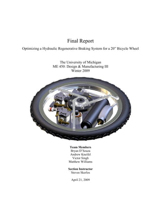
  • 1. Final Report Optimizing a Hydraulic Regenerative Braking System for a 20” Bicycle Wheel The University of Michigan ME 450: Design & Manufacturing III Winter 2009 Team Members Bryan D’Souza Andrew Kneifel Victor Singh Matthew Williams Section Instructor Steven Skerlos April 21, 2009
  • 2. 1 Executive Summary With a growing concern of climate change and decreasing availability of fossil fuels, the U.S. Environmental Protection Agency (EPA) has been researching hydraulic hybrid transportation systems. For seven years, the EPA and ME450 students at The University of Michigan (U-M) have collaborated on projects developing Hydraulic Regenerative Braking Systems (HRBS) for bicycles. These systems conserve energy that is normally lost during friction braking. The bike’s kinetic energy is used to drive hydraulic fluid into an accumulator via a pump, braking the vehicle. This stored energy is later released to accelerate the bike forward. This semester we have refined previous HRBS designs by optimizing the mechanical systems and improving safety. A key goal for our team was to build a functioning prototype 20” wheel that weighs less and has fewer moving parts than previous generations. Our team has made minimal changes to the extant hydraulic system, as the parts have been well-researched and recommended by our sponsor, David Swain of the EPA. Working with Mr. Swain, we created a list of customer requirements for this project. Table 1 below lists many of our key engineering specifications that were created to meet these requirements, as well as the final characteristics of the prototype. Our four categories for engineering specifications are safety, cost, weight, and functionality. Due to the conflicting nature of these specifications, it has been difficult to improve many of the bike’s systems without adversely affecting others. Compromises have been necessary in order to create a feasible design. Table 1: Summary of key engineering specifications Characteristic Target Prototype Front wheel assembly weight ≤ 30 lbs 24.75 lbs Bicycle load rating (rider weight) ≤ 160 lbs > 200 lbs System pressure as limited by relief valve ≤ 4200 psi ≤ 4200 psi Bicycle deceleration target 3.4 m/s2 – 3.6 m/s2 not available Bicycle acceleration target 2.0 m/s2 – 2.5 m/s2 not available Number of moving/rotating parts inside hub < 11 7 Prototype cost ≤ $1400 $1338 Many of the main hydraulic components have long acquisition lead times. To meet our goal of having a functional prototype by the end of the term, we expedited concept generation and selection so as to leave enough time to order and receive these parts. We created a detailed plan for the semester based on expected task requirements as well as these lead times. In reducing the weight of the prototype compared to previous designs, we have significantly reduced the number of gears, replaced the bulky fiberglass hub support system with a lightweight aluminum spoke system, and removed excess material from the internal support plate (“superbracket”). These modification choices were made from a broad number of concepts, based on a thorough analysis of the forces and torques required of each of the components. The main engineering obstacles to implementing these design improvements have been dealing with the nonstandard interface between metric and non-metric components, and determining the routing of the hydraulic circuit.
  • 3. 2 Table of Contents Executive Summary........................................................................................................................ 1  1 Abstract........................................................................................................................................ 5  2 Introduction.................................................................................................................................. 5  2.1 Background and Motivation.................................................................................................. 5  2.2 Project Description................................................................................................................ 6  3 Information Search....................................................................................................................... 7  3.1 Automotive Research and Applications................................................................................ 7  3.2 Bicycle Research and Applications....................................................................................... 8  3.3 Previous Bicycle Design Information ................................................................................... 9  3.4 Future Research................................................................................................................... 10  4 Project Requirements & Engineering Specifications................................................................. 10  4.1 Customer Requirements...................................................................................................... 10  4.2 Engineering Specifications.................................................................................................. 11  5 Concept Generation ................................................................................................................... 13  5.1 Functional Decomposition .................................................................................................. 13  5.2 Hydraulics ........................................................................................................................... 14  5.3 Powertrain & Packaging...................................................................................................... 15  5.4 Hub...................................................................................................................................... 15  5.5 Superbracket........................................................................................................................ 15  5.6 User Interface and Controls................................................................................................. 15  6 Concept Selection ...................................................................................................................... 16  6.1 Hydraulics ........................................................................................................................... 16  6.2 Powertrain ........................................................................................................................... 16  6.3 Hub...................................................................................................................................... 16  6.4 Superbracket........................................................................................................................ 17  6.5 User Interface & Controls ................................................................................................... 17  7 System Model ............................................................................................................................ 17  7.1 Pump and Motor Gear Reductions...................................................................................... 20  7.2 Motor and Pump Performance Curves................................................................................ 21  7.3 Bike System......................................................................................................................... 22 
  • 4. 3 7.4 Hydraulic System................................................................................................................ 23  7.5 Discussion of System Losses .............................................................................................. 24  7.6 Transmission Tuning Analysis............................................................................................ 25  8 Design of Selected Concept....................................................................................................... 26  8.1 Parameter Analysis.............................................................................................................. 26  8.1.1 Hydraulics..................................................................................................................... 26  8.1.2 Powertrain..................................................................................................................... 27  8.1.3 Hub ............................................................................................................................... 29  8.1.4 Superbracket................................................................................................................. 33  8.1.5 User Interface & Controls............................................................................................. 34  8.2 Final Design ........................................................................................................................ 35  8.2.1 Hydraulics..................................................................................................................... 35  8.2.2 Powertrain..................................................................................................................... 36  8.2.3 Hub ............................................................................................................................... 37  8.2.4 Superbracket................................................................................................................. 38  8.2.5 User Interface & Controls............................................................................................. 39  8.3 Prototype Design................................................................................................................. 40  8.4 Fabrication Plan................................................................................................................... 41  8.4.1 Hydraulics..................................................................................................................... 41  8.4.2 Powertrain..................................................................................................................... 42  8.4.3 Hub ............................................................................................................................... 43  8.4.4 Superbracket................................................................................................................. 46  8.4.5 User Interface & Controls............................................................................................. 48  8.5 Prototype Assembly ............................................................................................................ 49  8.6 Validation Plan.................................................................................................................... 53  9 Project Plan................................................................................................................................ 54  9.1 Phase I: Project Background & Specifications ................................................................... 55  9.2 Phase II: Concept Generation & Selection.......................................................................... 55  9.3 Phase III: Final Design........................................................................................................ 55  9.4 Phase IV: Alpha Prototype.................................................................................................. 55  10 Recommendations.................................................................................................................... 56 
  • 5. 4 10.1 Motor/Pump Selection....................................................................................................... 56  10.2 Clutch Selection ................................................................................................................ 56  10.3 Hydraulic Manifold........................................................................................................... 56  10.4 Superbracket stiffness analysis.......................................................................................... 56  10.5 Work with experts............................................................................................................. 57  10.6 Aggressive sourcing and manufacturing schedule............................................................ 57  10.7 Accurate CAD model........................................................................................................ 57  11 Conclusion ............................................................................................................................... 57  12 References................................................................................................................................ 58  13 Biographies .............................................................................................................................. 60  13.1 Bryan D’Souza.................................................................................................................. 60  13.2 Andrew Kneifel................................................................................................................. 60  13.3 Victor Singh ...................................................................................................................... 60  13.4 Matthew Williams............................................................................................................. 61  14 Acknowledgements.................................................................................................................. 61  Appendix A – QFD....................................................................................................................... 62  Appendix B – Gantt Chart ............................................................................................................ 63  Appendix C – Prototype Costs...................................................................................................... 64  Appendix D – Bill of Materials .................................................................................................... 65  Appendix E – Design Analysis Assignment................................................................................. 67  Spoke Material Selection .......................................................................................................... 67  Gear Material Selection............................................................................................................. 70  Spoke Environmental Performance........................................................................................... 72  Gear Environmental Performance............................................................................................. 74  Spoke Manufacturing Process................................................................................................... 77  Gear Manufacturing Process..................................................................................................... 77  Appendix F – DesignSafe Report ................................................................................................. 78  Appendix G – FMEA.................................................................................................................... 84  Appendix H – CAD Drawings...................................................................................................... 86 
  • 6. 5 1 Abstract The U.S. Environmental Protection Agency (EPA) is researching hydraulic hybrid transportation systems in an effort to address the growing concerns about global climate change and insatiable fossil fuel demands. Hydraulic hybrid vehicles use regenerative braking to store energy in pressurized fluids. This energy is then released to assist in vehicle acceleration. For the past seven years, ME450 students at The University of Michigan (U-M) have been developing designs for hydraulic hybrid bicycle systems. This semester we refined the design of a hydraulic hybrid system enclosed in a 20” bicycle wheel, with a focus on decreasing weight, improving safety, and reducing the number of moving parts. 2 Introduction This section outlines the origins of the hydraulic hybrid bicycle system concept at the EPA as well as the driving force for its development. A brief outline of the project’s scope for the Winter 2009 semester of ME450 is also presented below. 2.1 Background and Motivation Founded in 1970, the United States Environmental Protection Agency is a federal body tasked with correcting environmental damage and establishing guidelines to help protect the natural environment of the United States [1]. Research into clean energy, particularly for use in transportation, is the focus of several of the EPA’s efforts [2]. In cooperation with Eaton Corporation, United Parcel Service, Ford, International, and the U.S. Army, the EPA has developed several hydraulic hybrid vehicles for the purposes of improving fuel economy and reducing environmental impact [3]. The primary concept of hydraulic hybrid technology is to capture and utilize the energy that would otherwise be lost during braking and use it to accelerate the vehicle. As the vehicle brakes, a hydraulic pump connected to the drivetrain pumps hydraulic oil into the high-pressure accumulators. During vehicle acceleration, the energy stored in the accumulators is released back into the drivetrain, as the fluid flows through a hydraulic motor. This significantly lowers the amount of fuel needed to accelerate back to normal operating speeds [3]. The result of this regenerative braking is a marked improvement in fuel economy – a feature that is not just better for the environment, but also reduces fuel costs for the owner. A diagram showing this hydraulic regenerative braking system (HRBS) is shown in Figure 1 on page 6.
  • 7. 6 Figure 1: The hydraulic fluid’s path in an HRBS [4] The use of bicycles for commuting reduces fossil fuel use, greenhouse gas emissions, roadway congestion, and vehicle miles traveled while increasing the user’s physical health [5]. The EPA has demonstrated 20-40 percent fuel economy improvements by installing HRBS on vehicles with internal combustion engines [3]. The possibility of clean, efficient transportation with hydraulic assistance bears exploration. The EPA has been working with U-M students on hydraulic bicycle implementation since 2002, but the project has produced only one functional product. 2.2 Project Description The goal of this project is to develop a hydraulic regenerative braking system for a children’s 20” bicycle. Due to the difficult nature of scaling down a hydraulic system, and the comparative ease of scaling upwards, the intent of using a 20” bicycle is to analyze the weight, force, and torque issues inherent to the HRBS on a small scale. The EPA has been working on HRBS bicycles with ME450 students for the past seven years. Previous ME450 teams have worked on fitting these systems in 26” and 20” bicycle wheels. The primary focus of our work on the HRBS is refining the existing designs by improving safety, reducing weight, ensuring functionality, and lowering cost. We are designing an HRBS for a 20” wheel. Notably, one of the main goals is to reduce the device weight to 30 lbs without sacrificing mechanical robustness or safe pressure containment. We plan to retain the majority of the hydraulic components from past designs, as this technology has been well-researched and documented by David Swain and previous teams. By focusing on reducing moving parts, decreasing weight, and improving safety, we are further developing the understanding and implementation of HRBS technology through the fabrication of a functional prototype.
  • 8. 7 3 Information Search To gain a better understanding of hydraulic hybrid systems, our team surveyed a broad collection of information including research papers, previous ME450 reports, and EPA resources. This section of the report discusses the information we found regarding hydraulic hybrid vehicle technology. Hydraulic systems are used in a variety of applications such as machinery, braking systems, and energy storage. They are often used because of their ability to transfer large forces and convert kinetic energy into potential energy efficiently. To safely utilize this technology, many precautions must be taken to prevent high-pressure systems from rupturing. The EPA, U-M, and companies such as Eaton and Ford have been developing hydraulic hybrid systems for transportation applications including cars, trucks, and bicycles. Hydraulic hybrid bicycle technology has been pioneered through a partnership between the EPA and U-M. For seven years, ME450 students at U-M have been researching, designing, and building hydraulic hybrid bicycle systems using HRBS. These systems require improvements in safety, functionality, and performance. 3.1 Automotive Research and Applications The EPA has been developing hydraulic hybrid systems for three main automotive sectors: conventional vehicles, urban delivery trucks, and large SUVs and pickup trucks [3]. Each of these three sectors utilizes parallel and series hydraulic hybrid systems. Parallel hydraulic hybrid systems utilize HRBS to pump incompressible hydraulic fluid into high-pressure accumulators. Much of the energy that is lost through conventional braking systems is recovered through this technique. This energy is then released by directing the pressurized fluid through a hydraulic motor. This hydraulic motor powers the car during acceleration. These systems are ideal for vehicles that operate under frequent stop-and-go driving. Eaton uses parallel hybrid technology in its Hydraulic Launch Assist™ (HLA®) system designed for refuse trucks and buses [6]. A computer model of the HLA® system can be seen in Figure 2 on page 8.
  • 9. 8 Figure 2: Computer model of Eaton Corporation’s HLA® system for a refuse truck [6] Series hydraulic hybrid systems replace the conventional drivetrain with a hydraulic drivetrain [3]. The EPA applied this technology to a Ford Expedition. In this setup a pump powered by an internal combustion engine is used to force fluid through a hydraulic motor. The motor uses the energy stored in the fluid to power the vehicle. Along with a hydraulic drivetrain, series vehicles use HRBS to recover energy lost during braking. The regenerative system is directly plumbed with the hydraulic drivetrain and helps the vehicle accelerate. The EPA estimates that full hydraulic drive vehicles could result in 30-40 percent improvements in combined city/highway fuel economy and lower emissions [3]. The EPA-modified Ford Expedition obtained a combined city/highway fuel economy rating of 32 miles per gallon (mpg) compared to its standard 14 mpg rating [7, 8]. The EPA has teamed up with UPS, Eaton, International, and the U.S. Army to develop the next generation of urban delivery vehicles using hydraulic hybrid technology. UPS is currently the main customer of these vehicles and has provided the EPA with delivery trucks to retrofit. Using hydraulic hybrid technology, it has been shown that the fuel economy of these trucks can be increased from 10 mpg to 18 mpg. Delivery trucks are strong candidates for hybrid systems due to their frequent stops. 3.2 Bicycle Research and Applications Different forms of hybrid bicycles have been used for years, including mopeds and electric bicycles. Most of these systems are powered by gasoline or batteries. Some electric bicycles use regenerative braking, but this feature is not common. ME450 students at U-M have been developing hydraulic hybrid bicycles using regenerative braking as the energy source. This system is unique because it conserves kinetic energy by converting it to mechanical potential energy rather than refilling or recharging an energy source. In December 2006 a team of engineers from U-M and the EPA filed for a patent on hydraulic regenerative braking for a vehicle [9]. This patent is based on the functional hydraulic hybrid bicycle designed and built through ME450 in Fall 2005 and a research project in 2006. This bike has been important for benchmarking purposes. The HRBS was enclosed in a modified 26”
  • 10. 9 bicycle wheel. Testing this bike provided information on optimal acceleration and deceleration speeds, accumulator pressures, and hydraulic component size. In Winter 2007, an ME450 team created a redesign of the internal components of this bike. The final product was not a functional bike, but rather a model that demonstrated the process of hydraulic regenerative braking. Beginning in the Winter 2008 term, ME450 projects regarding HRBS began focusing on implementing a regenerative braking system into a 20” bike wheel. This is a standard wheel size for kids’ bikes. By shifting research towards smaller wheels, the goals were to lighten and refine the system. The 20” wheel containing the hydraulic hybrid system currently weighs about 70 lbs [10, 11]. As of the date of this report’s publishing, the system is not yet operational. In 2005 Parker-Hannifin Corporation began a design competition called the Parker Chainless Challenge [12]. For this contest, students design bicycles powered using hydraulic pumps and motors rather than chains. These bikes are series hydraulic systems. So far no team has entered a bicycle with regenerative braking. Students at U-M are working with the EPA to develop a hydraulic drive in parallel to an HRBS. U-M’s research for this design challenge began in 2007 as an ME450 project. 3.3 Previous Bicycle Design Information ME450 project teams have created numerous HRBS bicycle designs. The most notable work has been accomplished during the past four years. The first functional HRBS bicycle was finished in 2006 for a 26” wheel. This system utilized a single gear reduction between the motor/pump and a large gear rigidly connected to the wheel hub. This system did not have any method to disengage the gears from rotating during operation, meaning that while a rider was pedaling the bike, he was also pumping fluid through the hydraulic loop. This increased the pedaling resistance and decreased the bike’s efficiency. The hubs on this bike were made of carbon fiber and were connected to a custom machined aluminum rim. Both the covers and the rim were quite heavy. The custom rim decreased serviceability and increased cost. The thicknesses of the material used to make the superbracket (4mm) and front bike fork (0.125”) resulted in heavy structural components. In 2007, two teams refined the HRBS for manufacturability. A physical system was built; however, this system was not attached to a bike. The system that was built is housed within a display case and connected to a hand-powered hydraulic pump. Overall, the components used were comparable to those used in 2006. Teams in 2008 further developed the design by incorporating an HRBS into 20” bicycle wheel. Using a 20” wheel was chosen to constrain the design and motivate innovation. This design contained a few notable improvements, but also opened the door for our team to make more changes. The first main improvement was creating a system that no longer used bevel gears. Earlier designs had used bevel gears to redirect rotation. The bevel gears were difficult to align which decreased overall efficiency. In this design, the motor and pump were rotated 90° and only spur gears were used to transmit the rotational energy. The motors and pumps used in designs prior to 2008 were too large, so in 2008 smaller motors and pumps were selected for the system. Additionally clutches were installed to disengage the pump and motor from rotating when neither the braking nor the launch system was engaged.
  • 11. 10 These improvements were beneficial, but there is still much room for improvement. The 2008 bike is not yet functional. Work is currently being done by two former ME450 students to complete the bike, improve the design, and test its performance. The hubs used on the 2008 bicycle were made of ½” thick fiberglass. Combined, the two hubs weighed about 40 lbs. The gears used on this system were ½” thick solid steel weighing a total of 12 lbs. While these gears were robust, they were overdesigned for the number of cycles seen in this system. The front fork and superbracket were also unnecessarily heavy components. The superbracket was made of 4 mm thick 1018 steel and the front fork was made of tubes with 0.125” wall thickness. Excluding the fork, these components resulted in an HRBS weighing approximately 70 lbs. The 2008 system also posed problems for users effectively operating and maintaining it. The switches to engage the braking and launching systems were mounted on the bike frame directly in front of the seat tube. This setup would have required the rider to let go of the handlebars to engage and disengage the system. The bike was also difficult to service, as most of the components were welded together. There was an additional safety concern posed by the lack of a pressure relief device on the system. This could lead to unsafe operation, as the hydraulic components were only rated to 4000 psi. While much work has been done over the last seven years, more work is needed to effectively implement a hydraulic regenerative braking system on a bicycle. 3.4 Future Research In order to further develop a hydraulic hybrid system, more research will need to be completed. The main topics of research this term focused on gear design, hydraulic component sizing, hub strength, and superbracket stiffness. In order to decrease the overall system weight, we investigated gear layouts and strength. Hydraulic component sizing was important in reducing the number and size of fittings. We analyzed the hub strength using FEA to ensure our design is strong enough to safely support a rider. More research into superbracket stiffness will be necessary to prevent gear disengagement and component vibration. 4 Project Requirements & Engineering Specifications To outline the specifications for this project, we began by defining our customer requirements. We then translated these requirements into engineering specifications. This section of the report details these requirements and the resulting specifications. 4.1 Customer Requirements The customer requirements for this term, as outlined by our sponsor David Swain, are continuations of the past two semesters with an added emphasis on three major underlying themes–safety, performance, and cost– to guide the formation of our engineering specifications. Table 1 on page 11 shows a listing of our customer’s requirements, as grouped by the three major themes and their relative importance in each.
  • 12. 11 Table 1: Customer requirements categorized and listed by importance Relative Importance Safety Performance Cost High User Safe Lightweight Inexpensive Manufacturing Processes Natural Braking Rate Reliable Fastenable to a Stock Bicycle Easy to Use Efficient Material Costs Easy to Service Sufficient Launch Speed low 4.2 Engineering Specifications When translating the customer requirements into engineering specifications, cost and safety translated directly. However, performance split into weight and functionality, as we find both categories of high enough importance to be separate. The resultant engineering specifications are described in the following list. The interactions between these specifications and their correlation to the customer requirements can be seen on our Quality Function Deployment (QFD) in Appendix A on page 62. Note: Items in italics are integral to a complete design solution, but are not slated for implementation during the W09 timeframe. 1. Safety a. Hydraulic System i. Design shall incorporate pressure relief valve and line to dump high- pressure fluid to the low-pressure side in the event of overpressure (excess of 4200 psi). ii. High-pressure components and lines shall be sufficiently isolated from the user so as to prevent health and safety hazards in the event of a leak or rupture at 4200 psi. iii. High-pressure components and fittings shall be properly labeled for safety purposes. iv. Design shall provide a method by which the user may release the system pressure without accelerating the device. b. Power Transmission System i. Gears shall be sized to appropriately handle the torques/forces imposed upon them, without deforming or breaking themselves or the components to which they are mounted. ii. Moving/rotating components, especially those with teeth, shall be sufficiently isolated from the user so as to prevent mechanical safety hazards. iii. Moving/rotating components that present a mechanical hazard shall be properly labeled for safety purposes.
  • 13. 12 c. Electrical System i. Voltage and current sources shall be kept as far from the user as possible, such that the only interaction with the electrical system under normal circumstances is through use of well-insulated switches/toggles; in the event of an electrical system failure, the maximum exposure to electricity would result in less than 4 mA entering user. ii. No user interface devices such as switches/toggles shall be mounted in such a manner as to cause unsafe operation of the device. iii. Electrical components that impose dangerous voltage/current levels during normal operation, or could impose dangerous voltage/current levels in the event of an electrical malfunction, shall be properly labeled for safety purposes. d. General Safety i. Mechanical connection between front tire and front fork, regardless of modifications to original bicycle design, shall be robust enough to support a rider weighing 160 lbs based on the weight of a 95th percentile 14-year- old boy [13]. ii. Device deceleration should be limited to 3.6 m/s2 to prevent user from losing control during braking. iii. Device should retain stock rim brakes on the rear wheel to allow for braking in the event of a complete front-wheel system failure. iv. Brake controls should be integrated in such a way that conventional friction braking may be imposed by actuating the RBS control with more force (e.g. squeezing harder in the event of the RBS failing to decelerate the bike properly). 2. Weight a. Target i. Total front wheel assembly, including tire and rim, should weigh not more than 30 lbs. 3. Functionality a. Pedaling i. Impediment to pedaling when the HRBS is disengaged should be minimized through use of clutches or other disengagement components. b. Braking i. Device should respond within 500ms to call for braking. ii. Braking should be swift, but not violent; target range is 3.4 – 3.6 m/s2 based on testing completed on the functional 2006 bike. iii. Upon full stop, device should refrain from accelerating backwards (the system must utilize a check valve to prevent the release of high-pressure flow from the accumulator). c. Launch i. Device should respond within 500ms to call for launch. ii. Launch should be swift, but not rapid enough for the front tire to lose grip; target range is 2.0 – 2.5 m/s2 based on testing completed on the functional 2006 bike.
  • 14. 13 iii. Call for launch when device is already in motion should not damage or bind clutch, which could cause violent braking. d. Servicing i. Design should allow the typical user to perform standard maintenance operations, including replacing a worn/damaged inner tube. ii. Device should be able to be disassembled (i.e. no major components permanently connected). iii. Tire filling should not require disassembly. 4. Cost a. Target i. Total expended cost of the prototype (not including labor or components provided by sponsor) shall be not more than $1400. 5. Interactions Between Specifications a. Conflicting Specifications i. The weight target of 30 lbs (2.a.i) directly opposes several safety targets (1.a.i-ii, 1.b.i-ii, 1.d.i). Ensuring device safety by using larger, more-robust components will increase the total weight of the device. ii. The cost target of $1200 (4.a.i) directly or indirectly opposes several other targets (1.a.i, 1.a.iv, 1.b.i, 1.d.i, 1.d.iv, 2.a.i, 3.a.i). Components necessary to maximize safety, robustness, desirable operation, and weight reduction tend to be more costly. b. Consistent specifications i. Several safety targets (1.a.ii, 1.b.ii, 1.c.i) may be met simultaneously through proper device shielding. 5 Concept Generation To effectively generate a broad collection of concepts, we began by decomposing the main subsystems of the HRBS. After breaking down the subsystems, we listed the main components of each. Each team member then created a list of concepts for each of the components. We then met as a team to build on one another’s ideas and we created a master concept list. 5.1 Functional Decomposition Based on the unique history and relative complexity of our project, we followed a slightly different concept generation process than most teams. We began by decomposing the bicycle HRBS into five functional subsystems. These subsystems are hydraulics, powertrain, hub, superbracket, and user interface. Each of these subsystems contained at a minimum two major components. Figure 3 is a functional decomposition tree showing which components fall under which subsystem.
  • 15. 14 Figure 3: Functional decomposition tree outlining main components of each subsystem After completing the functional decomposition, we generated concepts for each of the subsystem components. By individually creating concepts and analyzing them as a team, we were able to attack each design problem from multiple angles. 5.2 Hydraulics The subsystem most refined by previous teams is hydraulics. This is also the subsystem with the longest lead-time items. As a result, many of our hydraulic components—including the pump, motor, high pressure accumulator, tubing & fittings, and low pressure reservoir—will remain the same as those specified by previous teams. In addition to the systems used on previous generations, it is important to include a pressure relief system to prevent over-pressurizing the system. This can be achieved by including a variable pressure relief valve or a burst disc. The valves category is made up of a check valve preventing high pressure flow from entering the pump and a directional valve to start and stop the launch process. There are various types of check valves that respond better to different pressures. The directional valve could either be a two-way or a three-way electronic valve. There are different types of each of these valves that
  • 16. 15 vary in their sealing method. Poppet valves seal quite well, leaking only a few drops per minute; spool valves can leak multiple milliliters per minute. 5.3 Powertrain & Packaging Powertrain decomposes into only two component categories, but it is very complicated due to the packaging constraints of a 20” bicycle wheel. In the past, the mechanical reduction was created using steel spur gears. We generated many concepts including plastic gears, phenolic gears, sprockets & chain, cogged belts, cables & pulleys, and friction rollers like those used to launch roller coasters. The second powertrain category is clutch mechanisms. A system is needed to disengage the pump and motor from the rotating hub when braking and launching are not engaged. Concepts to complete this task included electromechanical clutches (benchmark), mechanical clutches, roller clutches, and a custom clutch utilizing a linear actuator. 5.4 Hub The hub’s main roles on the bike are to support the rim, to interface with the mechanical reduction, and to enclose the system’s moving components. This hub rotates around the bike’s axle, which is stationary. Previous teams have created hubs made of carbon fiber and fiberglass. We included these in our concept list as well as aluminum sheet metal, vacuum formed plastic, and spokes with a thin cover. We developed another concept by combining the spoke and vacuum form designs. In this design a rigid skeletal structure would be used to support the bicycle and a thin plastic cover would enclose the system. 5.5 Superbracket The superbracket subsystem is made up of the superbracket and the bike’s axle. These components are rigidly connected together. The hub rotates on the axle and electric wiring exits the hub through the center of the axle. Designing the superbracket is a material selection and thickness optimization problem. The bracket needs to support the hydraulic and mechanical components and prevent the pump and motor’s output/input shafts from being loaded radially. To meet these criteria we created a list of potential materials, including steel, aluminum, fiberglass, tooling board, wood, carbon fiber, and plastic. Along with material selection we have discussed methods of increasing the bracket’s stiffness by using dimple dies, adding gussets, and adding angle iron reinforcements. 5.6 User Interface and Controls Previous designs incorporated a switchbox for controlling the brake and launch functions. This box was mounted on the frame of the bike directly in front of the seat. While functional, this forces the rider to let go of the handlebars with at least one hand to activate either system. In the event of a system braking failure, the rider would have to quickly adjust his hand position to activate the hand brake on the handlebar. One concept that could potentially solve this problem is to integrate the switch and the preexisting hand brake. This could be done by splicing a toggle switch into the cable. A light squeeze on the hand brake could activate the HRBS, while a hard squeeze would be enough to engage the friction brakes. Another option, provided that the bike is equipped with front and rear brakes, is to leave the rear hand brake unmodified and splice a toggle switch into the front hand brake cable. The launch activation could potentially be switched via a toggle switch mounted on the handlebars, or a pushbutton mounted on the
  • 17. 16 handlebars. If two switches are wired in parallel, there is the advantage that both switches must be activated for the launch to be triggered – this could be beneficial from a safety standpoint. 6 Concept Selection The concepts described above are suitable for general applications. For example, a belt & pulley power transmission is able to transfer torque and rotational speed. However, in our small and lightweight bicycle, such a mechanism is unreasonable due to the added difficulty in developing and sustaining tension. Because of this, reasonable feasibility was the primary criterion for all of our concept selections. Next, we compared each reasonable concept to a benchmark. In our case, the benchmark was the corresponding sub-assembly of the previous bicycle (Fall 2008). All concepts that were inferior to the benchmark were discarded because our design needs to improve on the previous iteration. The criteria used for comparing concepts included design characteristics, manufacturing, weight, safety, and cost. 6.1 Hydraulics For the hydraulic subsystem, the components remain relatively unchanged except for the 2-way valve, filter, and relief valve. The new 2-way valve has the same functionality and size as the benchmark, but leaks at a much lower rate (5 drops per minute vs. 5 ml per minute). The new filter is rated for particles as small as 2 microns, and is able to withstand pressures of up to 6000 psi (the previous design was only rated to 1500 psi). The addition of a relief valve will allow fluid pressurized above the recommended accumulator limit of 4000 psi to be dumped safely into the low pressure accumulator. No such mechanism was present on the benchmark subsystem. 6.2 Powertrain For the powertrain subsystem, we use drilled-out steel spur gears. These are much lighter than the current solid steel gears and offer similar strength properties – the lightening holes are strategically placed so as to remove excess material without sacrificing structural integrity. To disengage the pump from the rotating hub, we plan to use the same 24V electromechanical clutch used by previous teams. This clutch was selected because it is relatively small in size and can transmit a larger amount of torque than comparably sized clutches. We will use a Timken one-way clutch bearing to disengage the motor. When the motor is not engaged, it is disconnected from the gears. This clutch bearing requires no electrical power and weighs only 1/100th of a second clutch. Using the clutch bearing adds a precision machining process to create the proper press fit. 6.3 Hub The hub subsystem will not be made out of the benchmark material (thick fiberglass), but will be comprised of outer metal spokes covered by a vacuum formed ABS plastic cover. This substantially reduces the weight of the bicycle wheel and allow for quicker, more precise fabrication. A mold for the hub cover will be created out of Renboard using a CNC router. The vacuum forming will be done in the Art and Architecture woodshop.
  • 18. 17 6.4 Superbracket The superbracket will be made from a thin stainless steel plate with strategically placed reinforcements and lightening pockets. The circular envelope of the rim will be similar, but more pockets and unnecessary material will be cut out of the plate for significant weight savings. We will use thin angle iron to increase the rigidity while maintaining the weight reduction. The stiffness of the superbracket should not be compromised as the previous iteration was overdesigned. 6.5 User Interface & Controls The user interface will be reworked from the current setup of a box mounted between the rider’s legs. A handlebar mounted system will utilize two pushbutton switches that must be engaged simultaneously to activate the launch process. Instead of the front hand brake connecting to calipers on the front wheel, it will connect to a momentary switch that will activate the regenerative braking process. This lends itself to improved stability for the rider, as s/he does not have to remove a hand from the handlebars to operate either of the systems. Wires will run through the hollow shaft of the handlebars so that charged components are kept away from the user. Also, for additional safety, a lock and key setup will prevent unauthorized users from engaging any of the operations of the bicycle involving stored energy. 7 System Model One of our goals this semester was to more rigorously define the theoretical model of the HRBS through the use of computer simulation (Simulink), something that has not been attempted in previous generations. Though we have used it primarily to evaluate performance characteristics and design selection of the HRBS, we realize that this model will provide a valuable source of information to existing research as well as to future works. The theoretical model is constructed around the pump and motor transmission, from which the other subsystems developed overtime. The architecture of the theoretical model is shown in Figure 4 with the complete model shown in Figure 5 on page 18. All variables used in the model are listed in Table 2 on page 19. Figure 4: Architecture of theoretical model
  • 19. 18 Figure 5: Complete HRBS model
  • 20. 19 Table 2: List of all variables used in theoretical model Variable Subsystem Description ω1 Pump/Motor Transmission & Performance Curves Angular speed of pump or motor shaft and gear ω2 Pump/Motor Transmission Angular speed of 2nd gear on first reduction ω3 Pump/Motor Transmission Angular speed of clutched gear ω4 Pump/Motor Transmission Angular speed of main gear and front wheel ω5 Pump/Motor Transmission Angular speed of meshed 5th gear from other transmission R1 Pump/Motor Transmission Pitch radius of pump or motor gear R2 Pump/Motor Transmission Pitch radius of 2nd gear on first reduction R3 Pump/Motor Transmission Pitch radius of clutched gear R4 Pump/Motor Transmission Pitch radius of main gear R5 Pump/Motor Transmission Pitch radius of meshed 5th gear from other transmission I1 Pump/Motor Transmission Rotational inertia of pump or motor gear I2 Pump/Motor Transmission Rotational inertia of 2nd gear on first reduction I3 Pump/Motor Transmission Rotational inertia of clutched gear I4 Pump/Motor Transmission Rotational inertia of main gear I5 Pump/Motor Transmission Rotational inertia of 5th gear from other transmission Tin Pump/Motor Transmission & Performance Curves Torque applied by motor and pump shaft to transmission Tout Pump/Motor Transmission Torque applied to wheels Ts Pump/Motor Transmission Torque applied to clutched shaft F12 Pump/Motor Transmission Tangential force between motor or pump gear to 2nd gear on first reduction F34 Pump/Motor Transmission Tangential force between main gear and 1st gear on 2nd reduction P Performance Curves Pressure on high side of pump or motor Iw Bike System Inertia of front (and rear) wheel M Bike System Total mass of bike (w/ rider) Rw Bike System Radius of the front (and rear) wheel a Bike System Acceleration of the bike PnR Hydraulic System Precharge pressure of hydraulic accumulator VnR Hydraulic System Volume of nitrogen gas for empty accumulator Pg Hydraulic System Instantaneous nitrogen gas pressure Pc Hydraulic System Charge Pressure (for motor system) Vg Hydraulic System Instantaneous nitrogen gas volume Vfo Hydraulic System Initial fluid volume Vf Hydraulic System Instantaneous fluid volume Q Hydraulic System Flow rate of fluid into the accumulator
  • 21. 20 7.1 Pump and Motor Gear Reductions Figure 6 shows the geometry of the pump or motor transmission model (since both transmissions are the same). The transmission is a double reduction system (1 to 2 and 3 to 4) that amplifies the torque transmitted to the front wheel in two stages. Figure 6: Geometry and loadings of transmission system Using free body diagrams, the corresponding dynamics of each gear is determined in Equations 1-4. 1 1 1 12 ω I R F Tin = − (1) 2 2 2 12 ω = − I T R F s (2) ( ) 3 2 3 34 ω + = − s s I I R F T (3) 4 2 5 4 5 4 4 34 ω ⎟ ⎟ ⎠ ⎞ ⎜ ⎜ ⎝ ⎛ ⎟ ⎟ ⎠ ⎞ ⎜ ⎜ ⎝ ⎛ + = − R R I I T R F out (4) Although we could have largely simplified the above equations by algebraically combining them together, we chose not to in order to create separate subsystems for each gear. By doing this, we have the ability to incorporate additional information (frictional losses of tooth grinding for example) more efficiently if the need arises. Notice the inclusion of the 5th gear in the above equations and Figure 6. This is the satellite gear of the transmission not in operation. Though the two transmissions are independent, this satellite gear is meshed and will always rotate when either transmission is active. Alongside the dynamic analysis, a kinematic analysis reveals the mechanical reduction of the system, as shown in Equation 5. 4 3 4 1 2 3 1 2 2 1 2 1 ω = ω = ω = ω R R R R R R R R (5) Utilizing Equations 1-5, we formed the transmission model for the motor and pump as shown in Figure 7.
  • 22. 21 Figure 7: Motor (or Pump) transmission model 7.2 Motor and Pump Performance Curves The motor and pump generates unique torques based on pressure and rotational speed. Fortunately, the manufacturer of the pump and motor, Marzocchi, provides steady-state performance curves [14] that trace their behavior for various operating points (see Figure 8). Thus by mapping these performance curves, we could obtain the “plants” of the motor and pump. Figure 8: Motor and pump performance curves [14]
  • 23. 22 While a look-up table could have represented these curves, the operating pressure of our system is above the values shown on the graphs in Figure 8. This meant most of the data would have to be extrapolated and thus, a curve fit was considered. Noticing that the torque on the motor and pump shafts is a strong function of pressure and a weak function of speed, the curve fit was chosen by assuming that torque varied strongly with respect to pressure. The variation due to speed was assumed to be a percentage change from the average torque at the constant baseline pressure curve. The baseline pressure curve is the constant pressure line (on the performance curves) from which the curve fits are extrapolated. The selection of this baseline is chosen such that the extrapolated curve fits match as closely as possible to the actual performance curve data. The speed variation was modeled as a quadratic function due to its consistency with the shape of the performance curves. The generic curve fit is shown in Equation 6. ( ) ( )( ) eP d eP d c b a P T BASE in + + + ω + ω = ω 1 2 1 , (6) Here, ω is the angular speed of the motor/pump shaft (in rpm), P is the pressure on the high side of the pump/motor (in bars), PBASE is the baseline pressure, and the variables {a, b, c, d, e} are fit parameters. The fit parameters for both the motor and pump are shown in Table 3. The baseline pressures were chosen such that the extrapolated curves matched as closely as possible to the actual performance curves. Table 3: Curve fit parameters for motor and pump Motor Pump PBASE 230 Bar 190 Bar a* 1.400(10)-8 2.571(10)-8 b* -3.000(10)-5 -5.286(10)-5 c 2.216 2.260 d 0.2000 0.1219 e 0.01748 0.01130 * These parameters become extremely significant for pump and motor speeds exceeding 4000 rpm. 7.3 Bike System The analysis of the bike system was conducted using the free body diagram (FBD) in Figure 9, from which the governing equations of the bike were determined (Equation 7).
  • 24. 23 Figure 9: FBD of bike ( ) w w w out R a MR I T 2 2 + = (7) It is important to note that the FBD analysis assumes rolling without slip, that is, the bike does not skid during operation. Though this might be added later to validate the system model, it has not been included since rolling without slip generates the greatest loadings, making them useful for designing against failure. Also, since the front wheel is rigidly attached to the fourth gear of the transmission, its angular speed is ω4. The model of the bike system is shown in Figure 10. Figure 10: Bike system model 7.4 Hydraulic System The hydraulic accumulator was modeled under the assumption that the nitrogen gas inside the accumulator behaved isothermally. This is a reasonable assumption, as there shouldn’t be significant temperature variations in the accumulator during operation. Utilizing conservation laws, we determined the fluid and gas behavior of the fluid during operation (Equations 8-11). Definitions of the variables used in these equations are found in Table 2 on page 19. nR nR g g V P C V P = = (8) f nR g V V V − = (9) ∫ = − t fo f Qdt V V 0 (10)
  • 25. 24 nR c nR fo V P P V ⎟ ⎟ ⎠ ⎞ ⎜ ⎜ ⎝ ⎛ − = 1 (11) The flow rate through the system is dependent on the displacement of the pump and motor (assuming no energy losses in the pipes). Conveniently for us, Marzocchi also included flow rate curves [14] with the performance curves. By mapping these curves (Figure 11), we found a method of relating angular speed of the pump and motor to the flow rate. We chose a linear curve fit for the flows. Here Q is the flow rate (L/min) and ω is the angular speed of the pump/motor shaft (rpm). The corresponding fit parameter for both the motor and pump is shown in Table 4. ω = a Q (12) Figure 11: Pump and motor flow curves Table 4: Fit parameters for pump and motor flow rates Motor Pump a 0.00051 0.000635 7.5 Discussion of System Losses System losses are important to discuss since they directly impact the validity of the system model. Table 5 documents losses that have not been taken into account in each subsystem.
  • 26. 25 Table 5: Losses not modeled in the theoretical model Subsystem Losses not modeled Pump/Motor Transmission - Frictional losses and stored deformation energy of meshed gear teeth - Frictional losses in both clutches - Frictional losses in all bearings Performance Curves - Information uncertainty associated with back calculating transient behavior from steady-state Bike System - Frictional losses in all bearings - Air drag - Vibration of components Hydraulic System - Entrance/Exit effects at small openings (valves, pump, motor, accumulator, fittings) - Air pockets and or instantaneous cavitations due to motor/pump activity (model assumes fluid is continuous and is present at all times in the lines) - Heat and viscous losses in lines and hydraulic accumulator. 7.6 Transmission Tuning Analysis With an automobile, one must tune the transmission to obtain the highest efficiency from the engine. The HRBS is no different. Utilizing the model, we tested different gear reductions of the transmission to tune the system. The observed behavior of the system is documented in Table 6 for higher and lower reductions. Table 6: System behavior for variations in transmission reduction Reduction Changes Pump System Behavior Motor System Behavior Higher Reductions - Lower final charge pressure - Slightly higher final speed - Larger pump shaft speed - Larger motor shaft speed - Larger deceleration - Larger acceleration - Larger loadings on gears - Larger loadings on gears Lower Reductions - Larger final charge pressure - Slightly lower final speed - Lower pump shaft speed - Lower motor shaft speed - Lower deceleration - Lower acceleration - Lower loadings on gears - Lower loadings on gears Based on the information presented in Table 6, we can argue that to maximize performance we need to have as low a gear reduction as possible on the pump system (to acquire the largest accumulator pressure) and to have the highest gear reduction as possible on the motor system to
  • 27. 26 take advantage of the higher final speed. However, there are limitations. For one, the high accumulator pressure is limited to the design constraint of 4000 psi. This limited how low of a reduction we could go on the pump side. Another constraint is that the maximum operating speed of the pump and motor is 7000 rpm. This places an upper limit on possible gear reductions for our HRBS. Further complicating the matter is the fact that our maximum acceleration and decelerations levels are limited to those levels comfortable to a rider. These were previously determined by our sponsor David Swain and are listed in the engineering specifications. Testing stock gear sizes, we determined that a gear reduction of 17.5:1 for the both the pump and motor transmission satisfied all design constraints (see Table 7). We chose to use the same reduction for both the pump and motor to reduce the number of machining operations required for different gear geometries. Although we sacrifice some performance on the motor side (a slightly lower final speed), it does not outweigh the benefits of simpler machining schedules as well as reduced loadings on the transmission components. Table 7: Final gear sizes (pitch diameters) for transmission systems Pump Gear Reduction To Wheel Motor Gear Reduction G1 G2 G3 G4 G3 G2 G1 1” 3.5” 1” 5” 1” 3.5” 1” Final Pump Reduction 17.5:1 Final Motor Reduction 17.5:1 8 Design of Selected Concept Our system model created load, speed, and pressure information for our system. From this information and our component restrictions we created our final design. This section of the report outlines our final design and an analysis of it including such parameters as shape, material, and dimensions. 8.1 Parameter Analysis Throughout our design process we have analyzed concepts for performance. This section of the report documents these processes as they pertain to each subsystem of the HRBS. The selection of purchased and custom parts is described. 8.1.1 Hydraulics For safety purposes, the high-pressure side of the hydraulic system has been designed to withstand pressures of 6000 psi, even though the maximum expected system pressure is 4000 psi. Due to material considerations, this effectively excludes the use of brass fittings and components; while brass is commonly used in low-pressure systems, it is not strong enough to safely manage 6000 psi. Likewise, most aluminum fittings are not rated for this high of pressures. This leaves steel and stainless steel–the latter being preferred for its corrosion resistance. The gear pump and gear motor are manufactured by Marzocchi. Since they are 12-week lead- time items, there was only one parameter to decide: use the pump and motor available through
  • 28. 27 (and preferred by) our sponsor or order a new pump and motor with the knowledge that neither would arrive before the end of the semester. Since the W08 team had a significant problem with the Marzocchi lead time, we used the components we had on-hand. Impurities in the hydraulic fluid will cause accelerated wear on the pump and motor, and will prevent the poppet valves from seating properly. According to Norman Filter Company, LLC, the most damaging contaminants in hydraulic systems are in the range of 3-20 microns [15]. As such, we have chosen a 2-micron stainless steel filter manufactured by Swagelok. Since the filter is to be placed on the high-pressure side of the system, it is rated for pressures up to 6000 psi. If the filter was placed on the low-pressure side of the system, it would present a restriction to flow resulting in possible cavitation or vacuum generation inside the pump, both of which are damaging. Placing the filter directly after the pump maximizes the number of components receiving freshly-filtered fluid. To prevent backflow into the pump, the system utilizes a check valve after the filter. The check valve also keeps the fluid from back-flushing contaminants out of the filter and into the system. To reduce the resistance to opening, the crack pressure was chosen to be 1 psi. Manufactured by Swagelok, the check valve is made of stainless steel and is rated to 6000 psi. The hydraulic accumulator is another component made available by our sponsor; the only parameter to decide was the nitrogen pre-charge pressure, which was selected to be 2200 psi based on data collected in previous semesters. This pre-charge is lower than previous generations so that system functionality may be tested under reduced loading conditions. The system control valve had several options. Previous designs have used three-way spool valves, which leak at a rate of multiple mL/min. These valves are also available in poppet valve form, a style that leaks at a rate of drops/min. The two-way electronically-actuated poppet valve was chosen because it is smaller and leaks less than previous selections. The steel valve housing option was chosen over the aluminum option as the steel housing is rated to 6000 psi, whereas the aluminum housing is rated to 3300 psi. The main drawback of this selection is the larger weight of steel vs. aluminum. The requirements for the low-pressure reservoir are markedly less severe than the requirements for high-side components. The reservoir must be large enough to handle 150 mL of hydraulic fluid while not monopolizing too much space in the superbracket envelope. The material must also be nonreactive with hydraulic fluid. We chose a polyethylene terephthalate (PET) honey bottle, mainly due to size and cost considerations. 8.1.2 Powertrain Once the gear reductions were optimized using our Simulink model, we analyzed potential gear sizes and materials for our HRBS. We did this using the gear sizes listed in Table 7 on page 26. Selecting gears for this system was a complicated process, as gears are generally rated for around 10 million cycles. Selection was also made more difficult because gears generally fail through fatigue caused by sliding, rolling, bending, and compressing. Ultimately we utilized three different calculations to verify the performance of our gears. Our gear selection focused on two main characteristics: material and face width. Two secondary characteristics—pressure angle and diametral pitch—were directly related to the availability of the gears. Based on lead time and cost concerns, we ruled out custom gears as an option for this project.
  • 29. 28 Gears are made from a variety of materials so we focused our selection on steel, aluminum, phenolic, and nylon based on part availability, cost, and performance. The face width, or thickness, of the gear was important during selection as the hub is limited to four inches in width. Using the previous team’s design of ½” steel gears as a benchmark we limited the overall thickness of each gear to ½”. This value was also used in creating our initial CAD model, so we knew this was an upper bound. Table 8: Gear design requirements used for material selection Functions - Lightweight, strong gears Constraints - Must not yield - Maximum face width of 0.5” - No Custom gears Objectives - Minimize weight - Minimize cost Free Variables - Face width (gear thickness) - Diametral pitch (number of teeth per inch diameter) - Pressure angle (20° preferable over 14.5°) The gear material and pitch diameter drove the options for the pressure angle and the diametral pitch. When options were available, a 20° pressure angle was chosen over 14.5° for increased durability. Also, when choosing the diametral pitch the smaller value was selected to increase the size of each gear tooth. Following the basic limitations of gear availability we began calculating gear strength using the Lewis Equation with the Barth Revision [16]. This was recommended to our team by numerous companies including Emerson and Boston Gear. The Lewis equation determines the maximum allowable stress in a gear based on the tangential tooth load, face width, Lewis form factor, velocity factor, and allowable material stress. The allowable material stress is generally calculated as one-third of the material’s yield stress. This one-third factor allows for a wide range of variability and is designed to increase the life of the gear [17]. While using the Lewis equation we concurrently utilized equations describing the compressive and tensile stress applied to a gear tooth under given operation conditions. Once again, these calculations included a fractional factor on the allowable material stress. These equations swiftly eliminated the possibility of using phenolic and aluminum gears, but based on the fractional stress factors, we were not content with their accuracy based on our low cycle application. This led us to a third equation, which came from the American Gear Manufacturers Association (AGMA). This equation, called the AGMA strength equation, utilizes calculates the stress in a gear based on five operating parameters, a geometry factor, the face width, the allowable stress, and the diametral pitch [18]. We chose to base our gear selection on this equation because its five user-defined operating parameters provide a more accurate stress calculation.
  • 30. 29 The AGMA gear strength formula showed us that, while undesirable, the loading on our system requires the use of steel gears. Our calculations found that the first reduction required gears with a 3/8” face width and our second reduction required ½”. The diameter and face width requirements limited our gear options to a pressure angle of 14.5°. A summary of the selected gears is located in Table 9. Screenshots of the Excel worksheets used to make these calculations are located in Appendix E on page 67. Table 9: Gear selection summary Pump Gear Reduction To Wheel Motor Gear Reduction G1 G2 G3 G4 G3 G2 G1 1” 3.5” 1” 5” 1” 3.5” 1” Material Steel Steel Steel Steel Steel Steel Steel Face width (in) 0.375” 0.375” 0.5” 0.5” 0.5” 0.375” 0.375” Diametral Pitch 20 20 16 16 16 20 20 Pressure Angle 14.5° 14.5° 14.5° 14.5° 14.5° 14.5° 14.5° Weight (lbs) 0.059 .707 0.077 2.006 0.077 .707 0.059 The powertrain subsystem also includes two clutching mechanisms. The hydraulic system needs to disengage from the mechanical system so that normal riding does not pressurize the fluid or drive the motor shaft. The clutch device on the pump side needs to take ~80 in-lb of torque, and the clutch device on the motor side must be able to transmit a load of 56 in-lb (both figures are derived from the Simulink model). This can be accomplished through the use of an electromechanical clutch and a one-way needle bearing. The electromechanical clutch allows its two input shafts to rotate independent of one another when there is no voltage across it. When placed under a predetermined voltage differential, the shafts are effectively joined together in the desired direction. The pump gear train is therefore selectively isolated or joined to the hydraulic system while the bicycle is in motion. The one-way bearing serves the purpose of allowing the motor gear train to drive the bicycle but not the other way around (i.e. the bicycle’s forward motion cannot drive the motor gear train). 8.1.3 Hub The hub is a critical component of the HRBS since it supports the Superbracket, connects the front wheel to the bike, and transmits the power between the powertrain and bike. Its endurance to the rider weight as well as the torque applied by the pump or motor is crucial to rider safety and system functionality. Although the 2008 hub concept was able to meet this requirement, its implementation resulted in a total hub weight of 40 lbs which decreased system performance and rider comfort. The main focus of this term’s hub design is to reduce weight to improve performance by utilizing a skeletal structure and a non-structural cover. By making a skeletal hub design, we eliminated the structural aspect of the hub cover, thus drastically reducing the weight of the hub system compared to the 2008 design. This also leads to improved
  • 31. 30 serviceability as a person does not have to completely disassemble the structural components of the hub system to access the hydraulic components. The challenge of designing the hub emerges from the fact that the typical location to mount a spoke structure is occupied by a hydraulic system. To further complicate matters, the HRBS front wheel is required to endure torque loads, in which case it will receive larger loadings than a typical bike wheel. The large size of the hydraulic system eliminated the possibility of running straight members from the bearing carrier to the rim like a typical tension spoke system of a bike. Thus, the spokes had to sustain both compression and tension. Two different spoke layouts were considered: a radial layout where the spokes are arranged along the radius of the wheel and a tangent layout where the spokes are arranged tangent to the mounting holes of the bearing carrier (similar to a bicycle). Radial Spoke Layout: Due to its geometry (Figure 12 on page 30), it has good triangulation to support vertical loads. However, the resultant forces from the torque applied to the bearing carrier will be directed normal to the axis of the spokes, in which case loadings can only be transmitted by the spokes shifting slightly about the fixed point on the rim. This will induce a wobble in the spoke structure, inherently accelerating fatigue and decreasing life. Tangent Spoke Layout: Similar to a standard bicycle spoke design, this layout will direct torque loads along the axis of the spokes, eliminating the wobble inherent in the radial spoke layout. Furthermore, with the spokes being offset from the center of the wheel, the forces transmitted to the rim have a moment arm about the center. This allows for more efficient torque transmission to the wheel. The drawback to this design is that it is not as effective in supporting vertical loads since one spoke may receive a large percentage of the total loadings for certain wheel orientations. Figure 12: Spoke geometry layouts
  • 32. 31 A question of optimal geometry for loading arose for the tangent layout. Since the spokes are essentially long slender members, their ability to withstand tension is greater than their ability to withstand compression. Torque loads from deceleration are much higher than the torque loads from acceleration. Taking advantage of this fact, we decided that we could minimize possibility of failure by designing the orientation of the spokes such that they will be in compression for acceleration and in tension for deceleration. A combination of the two spoke layouts was initially considered. This allowed the strengths of one layout to offset the weaknesses of the other. However, we realized that by using the identical tangent layout on both sides, not only were we able to cut down on manufacturing complexity, but we were able to form triangulations of opposite spokes. This made the hub system more effective at supporting vertical loads. Since the rim is rigid and not prone to deformation from radial loads, we did not have to design the spokes to retain the arc shape of the rim. This eliminated the need for a large number of spokes. The smallest number of spokes we could chose on each side to properly constrain the geometry was three, which is what we chose. Due to the urgency of constructing a functional and stable structural hub to contain the HRBS, we were limited to materials that were readily available locally and easy to process. Accordingly, our material selection process bypassed a traditional analysis based purely on design constraints, and instead favored a real world analysis of specific stock materials from local vendors. Metals were chosen over all other materials since our available fabrication resources (Wilson Center and ME Shop) were specifically equipped to deal with these materials. The types of metals readily available to us were aluminum, copper alloys, steel alloys, and stainless steel. A difficult limitation to overcome was that stock material came in pre-specified cross sections. Our width limitations required us to use a 0.25” by 0.5” rectangular cross section. This proved to be a difficult constraint since it entailed a small cross section for the spokes to withstand buckling during compression, requiring a material with a large Yield Strength and Young’s Modulus. In addition, to keep the hub as light as possible, the material needed a low density. A summary of these design requirements is listed in Table 10. Table 10: Spoke requirements used for material selection Functions - Strong, lightweight spokes Constraints - Must not yield - Must not buckle - Must be metal (pre cut stocks available readily) Objectives - Minimize weight - Minimize lead time Free Variables - Hollow vs. solid We ultimately decided to use 6061-T651 aluminum with a 0.25”x0.5” rectangular cross section. 6061-T651 aluminum was chosen due to its low density for a lightweight design, high Young’s
  • 33. 32 Modulus to resist buckling, high Yield Strength, and good machinability. Though steels, stainless steels, and coppers all passed the loading criteria, the aluminum was by far the lightest. We conducted failure analysis by listing possible failure mechanisms in all loading conditions, determining the dominant failure mechanisms, and then designing against them. For compressive loadings, buckling was a concern. We analyzed yield by using an FEA package within Autodesk Inventor and buckling with the AISC Standard Buckling Equations [19], which are extensions of the Euler Elastic buckling and Johnson’s Inelastic buckling equations to account for structural defects and eccentricities in loading. The results of the FEA and buckling analysis are shown in Figure 13 and Table 11. Note: The loading scales on the two images are different. Figure 13: FEA analysis for failure by yield for the hub Braking (Deceleration) Launching (Acceleration)
  • 34. 33 Table 11: Failure analysis parameters and results for 6061-T651 Al. Negative values denote compression. Loading Parameters Magnitude Vertical Load 400 lb Torque (Deceleration) 600 lb-in Torque (Acceleration) 300 lb-in Localized Yield Analysis Deceleration Acceleration Failure Stress (Yield) [20] 34900 psi (241 MPa) 34900 psi (241 MPa) Actual Stress 13740 psi (94.7 MPa) 9700 psi (66.9 MPa) Buckling Analysis Deceleration Acceleration Failure Stress -7300 psi (50.3 MPa) -7300 psi (50.3 MPa) Actual Stress -852 psi (5.87 MPa) -824 psi (5.68 MPa) 8.1.4 Superbracket The superbracket provides support for all of the system’s internal components. Contained within the hub, it must be smaller in diameter than the rim – including the inner tube’s Schrader valve stem. A CAD image of the bracket is shown in Figure 14 on page 34. Since the overall width of the system is to be minimized, the superbracket must also be thin while retaining its strength. Based on these requirements, a maximum envelope for the superbracket was defined: it shall be no larger than 13” in diameter, and no thicker than 1/8”. This bracket will be made of steel. An alloy will be decided based on stiffness, cost, and availability at Alro. A non-corrosive steel alloy is ideal. To further reduce weight, as much unused material as possible will be removed from the superbracket. To determine where these unused sections will be, the system components were modeled in Autodesk Inventor and assembled within the diameter of the superbracket. The advantage of this method is that the components can be quickly and easily repositioned within the wheel. The primary constraints of this layout are the relative positions of the gears, and the position of the low-pressure reservoir relative to the pump. Gears must be positioned so as to mesh properly and connect the pump and motor to the drive gear. The low-pressure reservoir must be oriented so that fluid is driven into the pump upon braking.
  • 35. 34 Figure 14: Isometric CAD view of superbracket (overall diameter of 13”) 8.1.5 User Interface Controls The user interface consists of two points of interaction: the existing front brake lever and two pushbuttons mounted on the handlebar. The brake lever will initiate the regenerative braking process by actuating a toggle switch. This completes the braking circuit and allows the electromagnetic clutch to engage, which connects the powertrain to the hydraulics. The pushbuttons will activate the hydraulic pressure release system via the two-way valve to drive the powertrain, propelling the bicycle. User safety is very important in developing parameters for this subsystem. We want to minimize the electric current flowing near the user at all times. One solution is to design a low-current signal circuit to activate the appropriate high-current power circuit. This way the user is not exposed to potentially dangerous levels of electrical energy. Also, switching the high power circuit should not use any mechanical movement because of potential corrosion or other wear on the contacts from repeated engagement and disengagement. A great way to accomplish this is through the use of transistors, with a control circuit activating and deactivating its corresponding power circuit. The electromagnetic clutch and valve are on separate power circuits and have fixed electrical requirements. Both the clutch and valve require 24VDC, but they draw different amounts of current (250mA and 880mA, respectively). This constrains the electric system and forces all other electrical components to be designed and specified around these parameters. There are several power options for our user interface, but the use of batteries is the simplest method that we have found. They are portable and have acceptable energy density for our application. A problem with batteries is that they are rated based on open circuit tests and the actual voltage that they can maintain under electric load is nontrivially less and decreases with time. To combat this, a voltage regulator will be used. A negative consequence of this is that the input to the regulator must be somewhat higher than the expected 24VDC output in order to
  • 36. 35 guarantee a consistent output from the regulator. We will restrict the type and number of batteries to those combinations that yield a final voltage of 27VDC or more. 8.2 Final Design Our final design is broken into the five subsystems of our HRBS. The four subsystems located within the wheel are shown in an exploded view in Figure 15. This section of the report describes the design selection and the component functionality. Figure 15: Exploded view of CAD assembly showing four subsystems 8.2.1 Hydraulics The final hydraulic circuit is shown in Figure 16. An annotated drawing of this assembly is shown in detail in Figure 31 on page 51. The high-pressure accumulator and low-pressure reservoir are placed next to each other to save space. Upon braking, fluid will be pushed into the pump via gravity and bike deceleration. The filter is placed directly after the pump to maximize the system protection from particulates. The pressure relief valve is teed off of the line connecting the pump to the filter, so that the lines will not rupture in the event of the filter becoming clogged. The check valve is placed after the filter, followed by the two-way valve inlet. This inlet is connected to an always-open outlet on the other side of the two-way valve – which then goes to the high-pressure accumulator. When the two-way valve is triggered, the third port opens and fluid flows into the motor, and then back to the line from the low-pressure reservoir. The downside of working within such a tight envelope is that the circuit incorporates
  • 37. 36 several right-angle bends, across which will cause pressure losses in the fluid. Ideally, the system would be arranged in a straight line, so as to present minimal impediment to flow. Figure 16: CAD model of hydraulic circuit in 20” wheel 8.2.2 Powertrain Once the gear sizes were selected (see Table 7 on page 26), the main design concerns focused on attaching the gears to shafts. Based on gear availability and attachment goals, different torque transmission methods were chosen. A summary of the attachment methods is in Table 12. Table 12: Summary of gear to shaft attachments in radial and axial directions Pump Gear Reduction To Wheel Motor Gear Reduction G1 G2 G3 G4 G3 G2 G1 1” 3.5” 1” 5” 1” 3.5” 1” Radial Attachment Key Coupler Key Key Pinned Key One-way Bearing Key Coupler Axial Attachment Retaining Clip Retaining Clip Retaining Clip Set screw coupler Retaining Clip Retaining Clip Retaining Clip The most complicated gear attachment locations are on the pump/motor shafts. These shafts are metric (6mm diameter) with a key and M6 threads. Attached to each of these shafts is a gear with a 1” pitch diameter. Unless custom made, these gears cannot be purchased with a 6mm bore. We chose to purchase gears with a ½” finished bore with a keyway. To connect the gear to the shaft we will be using a set screw collar (6mm ID, ½” OD) as a coupler. On the outside of this collar we will machine a 1/8” keyway which matches that of the 1” gear. A support bearing on the end of this shaft will axially retain this gear. The bearing will be in a housing connected to the superbracket.
  • 38. 37 The 3.5” diameter gear on the pump reduction will be attached to a shaft connected to the electromechanical clutch. The shaft will use a 0.001” interference fit to transmit torque to the clutch. The gear will be connected to this shaft radially using a key and axially using a retaining clip. On the opposite side of the electromechanical clutch, torque will be transferred to a shaft through a 0.0002” press fit and a cross pin. Attached to this shaft will be a 1” diameter gear. Torque will be transferred through a 1/8” key. Axial motion will be limited by a retaining clip on the end of the shaft. The 3.5” diameter gear on the motor reduction will have a one-way clutch bearing pressed into it. This bearing will be the main means of torque transmission. A retaining clip will be used to axially restrain the gear from falling of the shaft and a Delrin spacer will be machined to offset the gear from the superbracket. On the other end of the shaft will be a 1” diameter gear connected with a key and a set screw. The main gear on our system has a diameter of 5”. A bearing will be pressed into the center of this gear. This bearing will rotate around the bike’s axle (which is stationary). On the inboard side of the gear, a set screw collar will be used to position the gear axially, with a thrust bearing between the gear and the collar. On the outboard side, the gear will be retained by the hub bearing carrier, to which it will be rigidly connected via three dowel pins pressed into the gear. These pins will slide into matching holes on the hub bearing carrier. Torque will be transmitted through these pins. The number of electromagnetic clutches on the market capable of supporting our system’s large torque and small size requirements is very limited. Several clutches were able to handle the torque, but they were large and heavy. Others were small enough, but their maximum torque rating was too small for expected operation. Ultimately we chose a clutch manufactured by Reell Precision Manufacturing which is the same clutch used by 2008 teams. It is rated to take 75 in- lbs – close to the maximum operating load of 80 in-lb. Selecting the one-way bearing was easier and was a simple constraint search with the correct shaft diameter and torque requirements. The final selection was a Timken one-way bearing sold by McMaster. 8.2.3 Hub The final hub skeleton design is shown in Figure 17. This hub consists of 3 spokes on each side, with the spoke layouts on one side forming triangulations with the spokes on the other. This geometry combination increases the effectiveness of supporting vertical loads. The spokes are made of solid 0.25”x0.5” 6061-T651 aluminum. This material has a relatively high stiffness that retains structural integrity and is still light enough to reduce weight. To reduce weight, the bearing carriers are also made of aluminum and have extra “lightening” holes drilled into them, which is also utilized on the drive side to attach to the main gear. The hub cover will be made from thermoformed ABS plastic that will be mounted over the hub skeleton. The CAD image of the hub cover is shown in Figure 17. A photograph of the final hub assembly is shown in Figure 18.
  • 39. 38 Figure 17: CAD of final hub design Figure 18: Side view of the final hub assembly without covers 8.2.4 Superbracket The layout of the components on the superbracket was dictated by the requirements of the powertrain as well as the design of the hydraulic circuit. The largest components – the high- pressure accumulator and the low-pressure reservoir – were placed in the model first. These were followed by the pump and motor, which are constrained to be in contact with the gearing of the powertrain. After these components were organized, the remaining smaller components were positioned so as to satisfy the hydraulic circuit requirements and the mechanical space considerations of the powertrain.
  • 40. 39 8.2.5 User Interface Controls For engaging and disengaging the different modes of our system, Metal-Oxide-Semiconductor Field-Effect Transistors (MOSFET) are used because of their ability to switch high-current circuits on and off based on a control static voltage differential (i.e. no current flow). This is good primarily for improved safety of the user in all operation modes (see Table 13 on page 39). Normal braking and acceleration do not require any user inputs and do not employ any of the improved HRBS functionality. In fact, the HRBS is disengaged during these operating modes and the bicycle can be operated like a standard bicycle. In the regenerative braking mode, the front-brake lever is pulled and a toggle switch is activated. This triggers the electromagnetic clutch to engage the pump, which uses the bicycle’s kinetic energy to pressurize the hydraulic fluid. To activate the hydraulic acceleration, the rider pushes two pushbuttons which energize the two-way valve circuit. This valve directs pressure through the motor, which drives the bicycle forward. When there are no user control inputs, the system reverts to a state where the HRBS is not engaged. Table 13: HRBS Operation Modes Mode Setting Result Normal Braking Pull rear-brake lever Rear friction brake engaged, HRBS disengaged Normal Acceleration/Cruise - HRBS disengaged Regenerative Braking Pull front-brake lever Hydraulic pump engaged Hydraulic Acceleration Depress two pushbuttons Fluid forced through motor Based on the expected current through the electromagnetic clutch and valve solenoid, we have specified all of our electrical components to withstand at least 1A. This includes the voltage regulator and transistors. We have put fuses in place that are rated to 1 A as a precautionary measure. The entire circuit will fit inside the wheel hub, save the user interface controls as described above. A schematic of the circuit is shown in Figure 19. The best combination and type of batteries for our application is four 9V batteries. They have a relatively small size and can fit into the hub. In addition, they have adequate capacity so that the batteries do not have to be replaced excessively often.
  • 41. 40 Figure 19: Electric schematic of user interface control system 8.3 Prototype Design The prototype that our team created is a full-scale, functional HRBS for a 20” bicycle that is developed according to our final design. Consequently, our prototype proves the design from concept selection to assembly and fabrication. The working device and accompanying analysis are the main deliverables for our sponsor and can be used to further holistic and practical hydraulic regenerative systems. We met or exceeded all of the established engineering specifications, and therefore fully satisfy each customer requirement, except for final functionality. These metrics have yet to be verified through our bicycle’s performance in validation tests (outlined in section 8.5). The one main design difference between the final design and our prototype is the electrical system. We removed the voltage regulator, transistors, and fuses from the electrical system of our alpha prototype to make sure that all components worked as required. This made the circuit much easier to test and allowed for easier assembly/disassembly. The actual circuit in the prototype is shown in Figure 20. Figure 20: Wiring diagram of electrical system used on prototype
  • 42. 41 8.4 Fabrication Plan Many components were fabricated for our HRBS. A summary of these components and the machining processes involved are covered in this section of the report and Table 14. Our assembly plan is listed in section 8.5. Table 14: Summary of HRBS machining processes Component Material Required Tools Machines Speed Location Hub mold Renboard; MDF CNC Router; sandpaper; Hand drill N/A Wilson Center (WC) Hub cover ABS plastic Vacuum Former N/A Art School woodshop Hub bearing carriers 6061 Aluminum Lathe; Arbor press 1150 rpm WC Hub spokes 6061 Aluminum Welder; Band Saw 30 fpm WC ME Superbracket 304 Stainless steel Water jet cutter Determined by CAM program ERC Axle Steel tube Mill; Lathe 600 rpm WC Fork Steel tube Mill; Tubing Notcher; TIG Welder 600 rpm WC Rim Aluminum Mill; Rotary table 600 rpm ME Gear lightening Steel Mill; Rotary chuck; Lathe 600 rpm (mill); 950 rpm (lathe) WC Gear keyways Steel Broaches; Arbor press N/A ME Gear shafts Steel Lathe; Mill 950 rpm WC Button carriers 6061 Aluminum Lathe; Tap 1150 rpm WC Electrical system Wires; solder Soldering iron N/A WC ME Clutch stabilizer housing 6061 Aluminum Lathe; Mill 1150 rpm WC Pump/Motor stabilizer collars 6061 Aluminum Lathe 1150 rpm WC 8.4.1 Hydraulics Most of the hydraulic subsystem components are purchased parts. This helps guarantee reliability of components under high pressures. However, three of our hydraulic components
  • 43. 42 needed modifications. These modifications were completed by Federal Fluid Power (FFP), as they have experience modifying hydraulic components. Both the pump and the motor were modified to remove metric fittings. FFP rebored the M10 ports and threaded them for SAE 6 fittings. This removed four fittings from our assembly. FFP also modified our two-way valve housing by boring two new holes. One is a ¼” national pipe thread (NPT) to allow the housing to serve as a tee-fitting in addition to being a valve housing. The other hole is a 1/8” NPT diagnostic port where our pressure gauge is attached. The only other hydraulic component requiring machining is our low pressure reservoir. We machined a Lexan cap using the CNC Router at the Wilson Center and threaded a hole for a tube fitting. 8.4.2 Powertrain All of our gears required machining processes. The required processes are summarized in the following bullets and in Table 15. • Bore (lathe 950 rpm): Some of the gears were bored on a lathe. This allowed for the gears to fit on the shafts or have bearings pressed into them. • Keyway (broach): Keyways (1/8”) were broached using an arbor press and broach set in the ME shop. • Removal of hub projection (lathe 950rpm): Each of our gears came from the manufacturer with a hub projection extending off the center of the gear. All of the gears had this projection removed on a lathe to reduce thickness and weight. • Lightening holes (mill 600rpm): Some of the gears had unnecessary material that was milled away to reduce weight. This is seen in Figure 21 on page 43. • Bearing Press-fit (arbor press): Two of our gears have bearings pressed into them. This was done using an arbor press. Table 15: Machining processes (and tool) required for each gear Pump Gear Reduction To Wheel Motor Gear Reduction G1 G2 G3 G4 G3 G2 G1 1” 3.5” 1” 5” 1” 3.5” 1” Bore (lathe) x x x Keyway (broach) x x x x x Removal of hub projection (lathe) x x x x x x x Lightening Holes (mill) x x x Bearing Press- fit (arbor press) x x
  • 44. 43 In addition to machining the gears, all of our shafts required machining processes to cut them to length and diameter. We added keyways to many of the shafts as well as retaining clip grooves to all of them. Figure 21: Milling lightening holes in a 3.5” gear 8.4.3 Hub The hub is composed of four main components: the hub covers, the bearing carriers, the spokes, and the rim. Each of these components required its own fabrication process. The ABS plastic hub cover was vacuum formed over a mold made of Ren Board. This mold was rough machined using the Wilson Center’s CNC Router and finished with sandpaper. Pictures of this process are in Figure 22. A base for the mold was made of ¾” thick medium-density fiberboard (MDF). The line separating the base from the mold was visible in the plastic following the vacuum forming. This created a cut line for post machining the hub cover. The vacuum forming process is shown in Figure 23.
  • 45. 44 Figure 22: Machining of hub mold on CNC Router Figure 23: Vacuum forming hub covers in the AA Woodshop The bearing carriers (qty 2) were machined out of 6061 aluminum. Both lathe and mill processes were required to give the part its shape. The lathe processes included turning the outside profile and boring an inside profile with a 0.0005” press fit for a bearing. Once the lathe operations were
  • 46. 45 complete, the holes in the flange were drilled on a mill. The bearing carrier is shown in Figure 24. Figure 24: Hub bearing carrier with bearing and spokes Spokes were machined out of ½” x ¼” rectangular 6061 aluminum stock. The spokes are composed of three pieces. Each side of the assembly requires three spokes. To simplify the manufacturing processes we chose to use the same spoke design for all six spokes. Maintaining machining tolerances on the spokes is important in guaranteeing wheel alignment. If spokes are of different lengths or if they mount poorly, the wheel will not spin true. Because of this, the spoke sections were milled to length and a mill was used to drill attachment holes. The sections were welded together. A jig, seen in Figure 25, was used to hold the assembly in place during welding. Figure 25: Hub spoke jig with three spoke segments mounted prior to welding The fourth component of the hub assembly is the rim. Holes were drilled through the rim for mounting the spokes and covers. For this process a mill with a rotary table was used. The manufacturing process is shown in Figure 26.
  • 47. 46 Figure 26: Aligning the rim on the mill in the ME Shop using a dial indicator 8.4.4 Superbracket To accurately cut all of the holes in our superbracket, we used the water jet cutter in the ERC. Utilizing the final CAD model of our system we created a 2D model of the superbracket that was the computer input in the ERC. Using a water jet cutter saved time, improved accuracy, and allowed us to machine more complex shapes to lighten the bracket. Along with the superbracket, a fork was made using steel tube. Tubes were welded onto the ends of the horizontal members of our current fork. This is shown in Figure 27 on page 47. Vertical tubes were fish-mouthed (shown in Figure 28 on page 47) and tee welded to the bottom of the horizontal tubes. Prior to welding, slots and through holes were milled into the bottom of the tubes to allow for axle placement and attachment. The fork was then painted and clear coated in the Wilson Center’s paint booth. This is shown in Figure 29 on page 48, next to the CAD model of the fork.
  • 48. 47 Figure 27: Horizontal fork members prior to welding Figure 28: Fish-mouthing fork tubes in the Wilson Center
  • 49. 48 Figure 29: Front fork – From CAD model to reality The axle was machined from ¾” × 0.083” steel tube. Holes were machined into either end for a through bolt that connects it to the fork. The tube was cut to length using a horizontal band saw. A third hole was drilled near the center of the tube to allow for wires to pass through the axle and out of the cover. 8.4.5 User Interface Controls The launch push-buttons located in the bar ends of the bicycle handlebar are mounted in carriers. These push-button carriers are made of 6061 aluminum. They were turned and drilled on a lathe at 1150rpm. The carriers were pressed into the ends of the bar ends (0.0005” interference fit). The master key switch was mounted in a similar manner, but on the horizontal end of the handlebar. The wiring for the user interface was contained inside the handlebar and run into the hub through the axle. The wires were placed into position in the handlebar and the ends were soldered to their respective components. This way, there is some slack and the wires will be less susceptible to damage or wear. Corrugated plastic tubing surrounds the wires that are outside of the handlebar (e.g., wire running to the axle) for tightness and safety. The toggle switch was mounted in a bracket attached to the handlebars. Electrical components were assembled in the Wilson Center and the ME Shop.