SlideShare a Scribd company logo
1 of 143
Download to read offline
Unit 1
FUNDAMENTALS OF IoT
1. INTRODUCTION TO IoT
 Today the Internet has become ubiquitous, has touched almost every corner of the
globe, and is affecting human life in unimaginable ways.
 We are now entering an era of even more pervasive connectivity where a very wide
variety of appliances will be connected to the web.
 One year after the past edition of the Clusterbook 2012 it can be clearly statedthat
the Internet of Things (IoT) has reached many different players and gainedfurther
recognition. Out of the potential Internet of Things application areas,Smart Cities
(and regions), Smart Car and mobility, Smart Home and assistedliving, Smart
Industries, Public safety, Energy & environmental protection,Agriculture and Tourism
as part of a future IoT Ecosystem (Figure 1.1) haveacquired high attention.
IoT Ecosystem.
 We are entering an era of the “Internet of Things” (abbreviated as IoT).There are 2
definitions: First one is defined by Vermesan and second by Pe˜na-L´opez
1. The Internet of Things as simply an interaction between the physical and digital
worlds. The digital world interacts with the physical world using a plethora of sensors
and actuators.
2. Another is the Internet of Things is defined as a paradigm in which computing and
networking capabilities are embedded in any kind of conceivable object.
www.rejinpaul.com
 We use these capabilities to query the state of the object and to change its state if
possible.
 In common parlance, the Internet of Things refers to a new kind of world where
almost all the devices and appliances that we use are connected to a network.
 We can use them collaboratively to achieve complex tasks that require a high degree
of intelligence.
 For this intelligence and interconnection, IoT devices areequipped with embedded
sensors, actuators, processors, andtransceivers.
 IoT is not a single technology; rather it is anagglomeration of various technologies
that work together intandem.
 Sensors and actuators are devices, which help in interactingwith the physical
environment.
 The data collected by thesensors has to be stored and processed intelligently in
order toderive useful inferences from it.
 Note that we broadly definethe term sensor; a mobile phone or even a microwave
ovencan count as a sensor as long as it provides inputs about itscurrent state
(internal state + environment).
 An actuator is adevice that is used to effect a change in the environment suchas the
temperature controller of an air conditioner.
 The storage and processing of data can be done on theedge of the network itself or
in a remote server.
 If any preprocessingof data is possible, then it is typically done at eitherthe sensor or
some other proximate device.
 The processeddata is then typically sent to a remote server.
 The storageand processing capabilities of an IoT object are also restrictedby the
resources available, which are often very constraineddue to limitations of size,
energy, power, and computationalcapability.
 As a result the main research challenge is toensure that we get the right kind of data
at the desired levelof accuracy.
 Along with the challenges of data collection, and handling, there are challenges in
communication aswell.
 The communication between IoT devices is mainlywireless because they are
generally installed at geographicallydispersed locations.
 The wireless channels often have high rates of distortion and are unreliable.
 In this scenario reliablycommunicating data without too many retransmissions is
animportant problem and thus communication technologiesare integral to the study
of IoT devices.
 We can directly modify the physical world through actuators or we may do
something virtually. For example,we can send some information to other smart
things.
www.rejinpaul.com
 The process of effecting a change in the physical world is often dependent on its
state at that point of time. This is called context awareness. Each action is taken
keeping in consideration the context because an application can behave differently
in different contexts.
 For example, a person may not like messages from his office to interrupt him when
he is on vacation. Sensors, actuators, compute servers, and the communication
network form the core infrastructure of an IoT framework. However, there are many
software aspects that need to be considered.
 First, we need a middleware that can be used to connect and manage all of these
heterogeneous components. We need a lot of standardization to connect many
different devices.
 The Internet of Things finds various applications in health care, fitness, education,
entertainment, social life, energy conservation, environment monitoring, home
automation, and transport systems.
1.2 TECHNOLOGIES INVOLVED IN IOT DEVELOPMENT: INTERNET/WEB AND NETWORKING
BASICS OSI MODEL
 Networking technologies enable IoT devices to communicate with other devices,
applications, and services running in the cloud.
 The internet relies on standardized protocols to ensure communication between
heterogeneous devices is secure and reliable.
 Standard protocols specify rules and formats that devices use to establish and
manage networks and transmit data across those networks.
 Networks are built as a “stack” of technologies. A technology such as Bluetooth LE
is at the bottom of the stack.
 While others such as such as IPv6 technologies (which is responsible for the logical
device addressing and routing of network traffic) are further up the stack.
Technologies at the top of the stack are used by the applications that are running
on top of those layers, such as message queuing technologies.
 This article describes widely adopted technologies and standards for IoT
networking. It also provides guidance for choosing one network protocol over
another. It then discusses key considerations and challenges related to networking
within IoT: range, bandwidth, power usage, intermittent connectivity,
interoperability, and security.
www.rejinpaul.com
NETWORKING STANDARDS AND TECHNOLOGIES
 The Open Systems Interconnection (OSI) model is an ISO-standard abstract model
is a stack of seven protocol layers.
 From the top down, they are: application, presentation, session, transport,
network, data link and physical. TCP/IP, or the Internet Protocol suite, underpins
the internet, and it provides a simplified concrete implementation of these layers
in the OSI model.
Figure 1. OSI and TCP/IP networking models
The TCP/IP model includes only four layers, merging some of the OSI model layers:
 Network Access & Physical Layer
This TCP/IP Layer subsumes both OSI layers 1 and 2. The physical (PHY) layer (Layer
1 of OSI) governs how each device is physically connected to the network with
hardware, for example with an optic cable, wires, or radio in the case of wireless
network like wifi IEEE 802.11 a/b/g/n). At the link layer (Layer 2 of OSI), devices are
identified by a MAC address, and protocols at this level are concerned with
physical addressing, such as how switches deliver frames to devices on the
network.
 Internet Layer
This layer maps to the OSI Layer 3 (network layer). OSI Layer 3 relates to logical
addressing. Protocols at this layer define how routers deliver packets of data
www.rejinpaul.com
between source and destination hosts identified by IP addresses. IPv6 is commonly
adopted for IoT device addressing.
 Transport Layer
The transport layer (Layer 4 in OSI) focuses on end-to-end communication and
provides features such as reliability, congestion avoidance, and guaranteeing that
packets will be delivered in the same order that they were sent. UDP (User
Datagram protocol) is often adopted for IoT transport for performance reasons.
 Application Layer
The application layer (Layers 5, 6, and 7 in OSI) covers application-level messaging.
HTTP/S is an example of an application layer protocol that is widely adopted across
the internet.
Although the TCP/IP and OSI models provide you with useful abstractions for discussing
networking protocols and specific technologies that implement each protocol, some
protocols don’t fit neatly into these layered models and are impractical. For example, the
Transport Layer Security (TLS) protocol that implements encryption to ensure privacy and
data integrity of network traffic can be considered to operate across OSI layers 4, 5, and 6.
NETWORK ACCESS AND PHYSICAL LAYER IOT NETWORK TECHNOLOGIES
IoT network technologies to be aware of toward the bottom of the protocol stack include
cellular, Wifi, and Ethernet, as well as more specialized solutions such as LPWAN,
Bluetooth Low Energy (BLE), ZigBee, NFC, and RFID.
NB-IoT is becoming the standard for LPWAN networks, according to Gartner. This IoT for
All article tells more about NB-IoT.
The following are network technologies with brief descriptions of each:
 LPWAN
(Low Power Wide Area Network) is a category of technologies designed for low-
power, long-range wireless communication. They are ideal for large-scale
deployments of low-power IoT devices such as wireless sensors. LPWAN
technologies include LoRa (LongRange physical layer protocol), Haystack, SigFox,
LTE-M, and NB-IoT (Narrow-Band IoT).
 Cellular
The LPWAN NB-IoT and LTE-M standards address low-power, low-cost IoT
communication options using existing cellular networks. NB-IoT is the newest of
www.rejinpaul.com
these standards and is focused on long-range communication between large
numbers of primarily indoor devices. LTE-M and NB-IoT were developed
specifically for IoT, however existing cellular technologies are also frequently
adopted for long-range wireless communication. While this has included 2G (GSM)
in legacy devices (and currently being phased out), CDMA (also being retired or
phased out), it also includes 3G, which is rapidly being phased out with several
network providers retiring all 3G devices. 4G is still active and will be until 5G
becomes fully available and implemented.
 Bluetooth Low Energy (BLE)
BLE is a low-power version of the popular Bluetooth 2.4 GHz wireless
communication protocol. It is designed for short-range (no more than 100 meters)
communication, typically in a star configuration, with a single primary device that
controls several secondary devices. Bluetooth operates across both layers 1 (PHY)
and 2 (MAC) of the OSI model. BLE is best suited to devices that transmit low
volumes of data in bursts. Devices are designed to sleep and save power when
they are not transmitting data. Personal IoT devices such as wearable health and
fitness trackers, often use BLE.
 ZigBee
ZigBee operates on 2.4GHz wireless communication spectrum. It has a longer
range than BLE by up to 100 meters. It also has a slightly lower data rate (250 kbps
maximum compared to 270 kbps for BLE) than BLE. ZigBee is a mesh network
protocol. Unlike BLE, not all devices can sleep between bursts. Much depends on
their position in the mesh and whether they need to act as routers or controllers
within the mesh. ZigBee was designed for building and home automation
applications. Another closely related technology to ZigBee is Z-Wave, which is also
based on IEEE 802.15.4. Z-Wave was designed for home automation. It has been
proprietary technology, but was recently released as a public domain
specification.
 NFC
The near field communication (NFC) protocol is used for very small range
communication (up to 4 cm), such as holding an NFC card or tag next to a reader.
NFC is often used for payment systems, but also useful for check-in systems and
smart labels in asset tracking.
 RFID
RFID stands for Radio Frequency Identification. RFID tags store identifiers and
data. The tags are attached to devices and read by an RFID reader. The typical
range of RFID is less than a meter. RFID tags can be active, passive, or assisted
passive. Passive tags are ideal for devices without batteries, as the ID is passively
www.rejinpaul.com
read by the reader. Active tags periodically broadcast their ID, while assisted
passive tags become active when RFID reader is present. Dash7 is a
communication protocol that uses active RFID that is designed to be used within
Industrial IoT applications for secure long-range communication. Similar to NFC, a
typical use case for RFID is tracking inventory items within retail and industrial IoT
applications.
 Wifi
Wifi is standard wireless networking based on IEEE 802.11a/b/g/n specifications.
802.11n offers the highest data throughput, but at the cost of high-power
consumption, so IoT devices might only use 802.11b or g for power conservation
reasons. Although wifi is adopted within many prototype and current generation
IoT devices, as longer-range and lower-power solutions become more widely
available, it is likely that wifi will be superseded by lower-power alternatives.
 Ethernet
Widely deployed for wired connectivity within local area
networks, Ethernet implements the IEEE 802.3 standard. Not all IoT devices need
to be stationery wireless . For example, sensor units installed within a building
automation system can use wired networking technologies like Ethernet. Power
line communication (PLC), an alternative hard-wired solution, uses existing
electrical wiring instead of dedicated network cables.
INTERNET LAYER IOT NETWORK TECHNOLOGIES
Internet layer technologies (OSI Layer 3) identify and route packets of data. Technologies
commonly adopted for IoT are related to this layer, and include IPv6, 6LoWPAN, and RPL.
 IPv6
At the Internet layer, devices are identified by IP addresses. IPv6 is typically used
for IoT applications over legacy IPv4 addressing. IPv4 is limited to 32-bit
addresses, which only provide around 4.3 billion addresses in total, which is less
than the current number of IoT devices that are connected, while IPv6 uses 128
bits, and so provides 2 128
addresses (around 3.4 × 10 38
or 340 billion billion billion
billion) addresses. In practice, not all IoT devices need public addresses. Of the
tens of billions of devices expected to connect via the IoT over the next few years,
many will be deployed in private networks that use private address ranges and
only communicate out to other devices or services on external networks by using
gateways.
 6LoWPAN
The IPv6 Low Power Wireless Personal Area Network (6LoWPAN) standard allows
IPv6 to be used over 802.15.4 wireless networks. 6LoWPAN is often used for
wireless sensor networks, and the Thread protocol for home automation devices
also runs over 6LoWPAN.
www.rejinpaul.com
 RPL
The Internet Layer also covers routing. IPv6 Routing Protocol for Low-Power and
Lossy Networks (RPL) is designed for routing IPv6 traffic over low-power networks
like those networks implemented over 6LoWPAN. RPL (pronounced “ripple”) is
designed for routing packets within constrained networks such as wireless sensor
networks, where not all devices are reachable at all times and there are high or
unpredictable amounts of packet loss. RPL can compute the optimal path by
building up a graph of the nodes in the network based on dynamic metrics and
constraints like minimizing energy consumption or latency.
APPLICATION LAYER IOT NETWORK TECHNOLOGIES
HTTP and HTTPS are ubiquitous across internet applications, which is true also within IoT,
with RESTful HTTP and HTTPS interfaces widely deployed. CoAP (Constrained Application
Protocol) is like a lightweight HTTP that is often used in combination with 6LoWPAN over
UDP. Messaging protocols like MQTT, AMQP, and XMPP are also frequently used within
IoT applications:
 MQTT
Message Queue Telemetry Transport (MQTT) is a publish/subscribe-based
messaging protocol that was designed for use in low bandwidth situations,
particularly for sensors and mobile devices on unreliable networks.
 AMQP
Advanced Message Queuing Protocol (AMQP) is an open standard messaging
protocol that is used for message-oriented middleware. Most notably, AMQP is
implemented by RabbitMQ.
 XMPP
The Extensible Messaging and Presence Protocol (XMPP) was originally designed
for real-time human-to-human communication including instant messaging. This
protocol has been adapted for machine-to-machine (M2M) communication to
implement lightweight middleware and for routing XML data. XMPP is primarily
used with smart appliances.
Your choice of technologies at this layer will depend on the specific application
requirements of your IoT project. For example, for a budget home automation system
that involves several sensors, MQTT would be a good choice as it is great for
implementing messaging on devices without much storage or processing power because
the protocol is simple and lightweight to implement.
www.rejinpaul.com
IOT NETWORKING CONSIDERATIONS AND CHALLENGES
When you consider which networking technologies to adopt within your IoT application,
be mindful of the following constraints:
 Range
 Bandwidth
 Power usage
 Intermittent connectivity
 Interoperability
 Security
Range
Networks can be described in terms of the distances over which data is typically
transmitted by the IoT devices attached to the network:
 PAN(PersonalAreaNetwork)
PAN is short-range, where distances can be measured in meters, such as a
wearable fitness tracker device that communicates with an app on a cell phone
over BLE.
 LAN(LocalAreaNetwork)
LAN is short- to medium-range, where distances can be up to hundreds of meters,
such as home automation or sensors that are installed within a factory production
line that communicate over wifi with a gateway device that is installed within the
same building.
 MAN (Metropolitan Area Network)
MAN is long-range (city wide), where distances are measured up to a few
kilometers, such as smart parking sensors installed throughout a city that are
connected in a mesh network topology.
 WAN (Wide Area Network)
WAN is long-range, where distances can be measured in kilometers, such as
agricultural sensors that are installed across a large farm or ranch that are used to
monitor micro-climate environmental conditions across the property.
Your network should retrieve data from the IoT devices and transmit to its intended
destination. Select a network protocol that matches the range is required. For example,
do not choose BLE for a WAN application to operate over a range of several kilometers. If
transmitting data over the required range presents a challenge, consider edge computing.
Edge computing analyzes data directly from the devices rather than from a distant data
center or elsewhere.
www.rejinpaul.com
Bandwidth
Bandwidth is the amount of data that can be transmitted per unit of time. It limits the
rate at which data can be collected from IoT devices and transmitted upstream.
Bandwidth is affected by many factors, which include:
 The volume of data each device gathers and transmits
 The number of devices deployed
 Whether data is being sent as a constant stream or in intermittent bursts, and if
any peak periods are notable
The packet size of the networking protocol should match up with the volume of data
typically transmitted. It is inefficient to send packets padded with empty data. In
contrast, there are overheads in splitting larger chunks of data up across too many small
packets. Data transmission rates are not always symmetrical (that is, upload rates might
be slower than download rates). So, if there is two-way communication between devices,
data transmission needs to be factored in. Wireless and cellular networks are
traditionally low bandwidth, so consider whether a wireless technology is the right choice
for high-volume applications.
Consider whether all raw data must be transmitted. A possible solution is to capture less
data by sampling less frequently. Thus, you’ll capture fewer variables and may filter data
from the device to drop insignificant data. If you aggregate the data before you transmit
it, you reduce the volume of data transmitted. But this process affects flexibility and
granularity in the upstream analysis. Aggregation and bursting are not always suitable for
time-sensitive or latency-sensitive data. All of these techniques increase the data
processing and storage requirements for the IoT device.
Power usage
Transmitting data from a device consumes power. Transmitting data over long ranges
requires more power than over a short range. You must consider the power source – such
as a battery, solar cell, or capacitor – of a device and its total lifecycle. A long and
enduring lifecycle will not only provide greater reliability but reduce operating cost. Steps
may be taken to help achieve longer power supply lifecycles. For example, to prolong the
battery life, you can put the device into sleep mode whenever it is idle. Another best
practice is to model the energy consumption of the device under different loads and
different network conditions to ensure that the device’s power supply and storage
capacity matches with the power that is required to transmit the necessary data by using
the networking technologies that you adopted.
www.rejinpaul.com
Intermittent connectivity
IoT devices aren’t always connected. In some cases, devices are designed to connect
periodically. However, sometimes an unreliable network might cause devices to drop off
due to connectivity issues. Sometimes quality of service issues, such as dealing with
interference or channel contention on a wireless network using a shared spectrum.
Designs should incorporate intermittent connectivity and seek any available solutions to
provide uninterrupted service, should that be a critical factor for IoT landscape design.
Interoperability
Devices work with other devices, equipment, systems, and technology; they are
interoperable. With so many different devices connecting to the IoT, interoperability can
be a challenge. Adopting standard protocols has been a traditional approach for
maintaining interoperability on the Internet. Standards are agreed upon by industry
participants and avoid multiple different designs and directions. With proper standards,
and participants who agree to them, incompatibility issues, hence interoperability issues
may be avoided.
However, for the IoT, standardization processes sometimes struggle to keep up with
innovation and change. They are written and released based on upcoming versions of
standards that are still subject to change. Consider the ecosystem around the
technologies: Are they widely adopted? Are they open versus proprietary? How many
implementations are available?
Using these questions to plan your IoT networks help plan better interoperability for a
more robust IoT network.
Security
Security is a priority. Selection of networking technologies that implement end-to-end
security, including authentication, encryption, and open port protection is crucial. IEEE
802.15.4 includes a security model that provides security features that include access
control, message integrity, message confidentiality, and replay protection, which are
implemented by technologies based on this standard such as ZigBee.
Consider the following factors in shaping a secure and safe IoT network:
 Authentication
Adopt secure protocols to support authentication for devices, gateways, users,
services, and applications. Consider using adopting the X.509 standard for device
authentication.
www.rejinpaul.com
 Encryption
If you are using wifi, use Wireless Protected Access 2 (WPA2) for wireless network
encryption. You may also adopt a Private Pre-Shared Key (PPSK) approach. To
ensure privacy and data integrity for communication between applications, be
sure to adopt TLS or Datagram Transport-Layer Security (DTLS), which is based on
TLS, but adapted for unreliable connections that run over UDP. TLS encrypts
application data and ensures its integrity.
 Port protection
Port protection ensures that only the ports required for communication with the
gateway or upstream applications or services remain open to external
connections. All other ports should be disabled or protected by firewalls. Device
ports might be exposed when exploiting Universal Plug and Play (UPnP)
vulnerabilities. Thus, UPnP should be disabled on the router.
The IoT World Forum (IoTWF) Standardized Architecture
In 2014 the IoTWF architectural committee (led by Cisco, IBM, Rockwell Automation, and
others)published a seven-layer IoT architectural reference model. While various IoT
reference models exist, theone put forth by the IoT World Forum offers a clean, simplified
perspective on IoT and includes edgecomputing, data storage, and access. It provides a
succinct way of visualizing IoT from a technicalperspective. Each of the seven layers is
broken down into specific functions, and security encompassesthe entire model. Figure
belowdetails the IoT Reference Model published by the IoTWF.
As shown in Figure 2-2, the IoT Reference Model defines a set of levels with control flowing
from thecenter (this could be either a cloud service or a dedicated data center), to the edge,
www.rejinpaul.com
which includessensors, devices, machines, and other types of intelligent end nodes. In
general, data travels up the stack,originating from the edge, and goes northbound to the
center. Using this reference model, we are able toachieve the following:
 Decompose the IoT problem into smaller parts
 Identify different technologies at each layer and how they relate to one another
 Define a system in which different parts can be provided by different vendors
 Have a process of defining interfaces that leads to interoperability
 Define a tiered security model that is enforced at the transition points between
levels
The following sections look more closely at each of the seven layers of the IoT Reference
Model.
Layer 1: Physical Devices and Controllers Layer
The first layer of the IoT Reference Model is the physical devices and controllers layer. This
layer is hometo the “things” in the Internet of Things, including the various endpoint devices
and sensors that send andreceive information. The size of these “things” can range from
almost microscopic sensors to giantmachines in a factory. Their primary function is
generating data and being capable of being queriedand/or controlled over a network.
Layer 2: Connectivity Layer
In the second layer of the IoT Reference Model, the focus is on connectivity. The most
important functionof this IoT layer is the reliable and timely transmission of data. More
specifically, this includestransmissions between Layer 1 devices and the network and
between the network and informationprocessing that occurs at Layer 3 (the edge computing
layer).As you may notice, the connectivity layer encompasses all networking elements of IoT
and doesn’t reallydistinguish between the last-mile network (the network between the
sensor/endpoint and the IoT gateway,discussed later in this chapter), gateway, and
backhaul networks. Functions of the connectivity layer aredetailed in Figure 2-3.
www.rejinpaul.com
Layer 3: Edge Computing Layer
Edge computing is the role of Layer 3. Edge computing is often referred to as the “fog” layer
and isdiscussed in the section “Fog Computing,” later in this chapter. At this layer, the
emphasis is on datareduction and converting network data flows into information that is
ready for storage and processing byhigher layers. One of the basic principles of this
reference model is that information processing is initiated
as early and as close to the edge of the network as possible. Figure 2-4 highlights the
functions handledby Layer 3 of the IoT Reference Model.
Another important function that occurs at Layer 3 is the evaluation of data to see if it can be
filtered oraggregated before being sent to a higher layer. This also allows for data to be
reformatted or decoded,making additional processing by other systems easier. Thus, a
critical function is assessing the data to seeif predefined thresholds are crossed and any
action or alerts need to be sent.
Upper Layers: Layers 4–7
The upper layers deal with handling and processing the IoT data generated by the bottom
layer. For thesake of completeness, Layers 4–7 of the IoT Reference Model are summarized
in Table 2-2.
www.rejinpaul.com
M2M Communication
Machine-to-machine communication, or M2M, is exactly as it sounds: two machines
“communicating,” or exchanging data, without human interfacing or interaction. This
includes serial connection, powerline connection (PLC), or wireless communications in the
industrial Internet of Things (IoT). Switching over to wireless has made M2M communication
much easier and enabled more applications to be connected.
In general, when someone says M2M communication, they often are referring to cellular
communication for embedded devices. Examples of M2M communication in this case would
be vending machines sending out inventory information or ATM machines getting
authorization to despense cash.
As businesses have realized the value of M2M, it has taken on a new name: the Internet of
Things (IoT). IoT and M2M have similar promises: to fundamentally change the way the
world operates. Just like IoT, M2M allows virtually any sensor to communicate, which opens
up the possibility of systems monitoring themselves and automatically responding to
changes in the environment, with a much reduced need for human involvement. M2M and
IoT are almost synonymous—the exception is IoT (the newer term) typically refers to
wireless communications, whereas M2M can refer to any two machines—wired or
wireless—communicating with one another.
www.rejinpaul.com
Traditionally, M2M focused on “industrial telematics,” which is a fancy way of explaining
data transfer for some commercial benefit. But many original uses of M2M still stand today,
like smart meters. Wireless M2M has been dominated by cellular since it came out in the
mid-2000’s with 2G cell networks. Because of this, the cellular market has tried to brand
M2M as an inherently cellular thing by offering M2M data plans. But cellular M2M is only
one subsection of the market, and it shouldn’t be thought of as a cellular-only area.
How M2M Works
As previously stated, machine-to-machine communication makes the Internet of Things
possible. According to Forbes, M2M is among the fastest-growing types of connected device
technologies in the market right now, largely because M2M technologies can connect
millions of devices within a single network. The range of connected devices includes
anything from vending machines to medical equipment to vehicles to buildings. Virtually
anything that houses sensor or control technology can be connected to some sort of
wireless network.
This sounds complex, but the driving thought behind the idea is quite simple. Essentially,
M2M networks are very similar to LAN or WAN networks, but are exclusively used to allow
machines, sensors, and controls, to communicate. These devices feed information they
collect back to other devices in the network. This process allows a human (or an intelligent
control unit) to assess what is going on across the whole network and issue appropriate
instructions to member devices.
M2M Applications
The possibilities in the realm of M2M can be seen in four major use cases, which we’ve
detailed below:
1. MANUFACTURING
Every manufacturing environment—whether it’s food processing or general product
manufacturing—relies on technology to ensure costs are managed properly and processes
are executed efficiently. Automating manufacturing processes within such a fast-paced
environment is expected to improve processes even more. In the manufacturing world, this
could involve highly automated equipment maintenance and safety procedures.
For example, M2M tools allow business owners to be alerted on their smartphones when an
important piece of equipment needs servicing, so they can address issues as quickly as they
arise. Sophisticated networks of sensors connected to the Internet could even order
replacement parts automatically.
www.rejinpaul.com
2. HOME APPLIANCES
IoT already affects home appliance connectivity through platforms like Nest. However, M2M
is expected to take home-based IoT to the next level. Manufacturers like LG and Samsung
are already slowly unveiling smart home appliances to help ensure a higher quality of life for
occupants.
For example, an M2M-capable washing machine could send alerts to the owners’ smart
devices once it finishes washing or drying, and a smart refrigerator could automatically
order groceries from Amazon once its inventory is depleted. There are many more examples
of home automation that can potentially improve quality of life for residents, including
systems that allow members of the household to remotely control HVAC systems using their
mobile devices. In situations where a homeowner decides to leave work early, he or she
could contact the home heating system before leaving work to make sure the temperature
at home will be comfortable upon arrival.
3. HEALTHCARE DEVICE MANAGEMENT
One of the biggest opportunities for M2M technology is in the realm of health care. With
M2M technology, hospitals can automate processes to ensure the highest levels of
treatment. Using devices that can react faster than a human healthcare professional in an
emergency situation make this possible. For instance, when a patient’s vital signs drop
below normal, an M2M-connected life support device could automatically administer
oxygen and additional care until a healthcare professional arrives on the scene. M2M also
allows patients to be monitored in their own homes instead of in hospitals or care centers.
For example, devices that track a frail or elderly person’s normal movements can detect
when he or she has had a fall and alert a healthcare worker to the situation.
4. SMART UTILITY MANAGEMENT
In the new age of energy efficiency, automation will quickly become the new normal. As
energy companies look for new ways to automate the metering process, M2M comes to the
rescue, helping energy companies automatically gather energy consumption data, so they
can accurately bill customers. Smart meters can track how much energy a household or
business uses and automatically alert the energy company, which supplants sending out an
employee to read the meter or requiring the customer to provide a reading. This is even
more important as utilities move toward more dynamic pricing models, charging consumers
more for energy usage during peak times.
A few key analysts predict that soon, every object or device will need to be able to connect
to the cloud. This is a bold but seemingly accurate statement. As more consumers, users,
and business owners demand deeper connectivity, technology will need to be continually
www.rejinpaul.com
equipped to meet the needs and challenges of tomorrow. This will empower a wide range of
highly automated processes, from equipment repairs and firmware upgrades to system
diagnostics, data retrieval, and analysis. Information will be delivered to users, engineers,
data scientists, and key decision-makers in real time, and it will eliminate the need for
guesswork.
The Value Of M2M
Growth in the M2M and IoT markets has been growing rapidly, and according to many
reports, growth will continue. Strategy Analytics believes that low power, wide-area
network (LPWAN) connections will grow from 11 million in 2014 to 5 billion in 2022.
And IDC says the market for worldwide IoT solutions will go from $1.9 trillion in 2013 to $7.1
trillion in 2020.
Many big cell operators, like AT&T and Verizon, see this potential and are rolling out their
own M2M platforms. Intel, PTC, and Wipro are are all marketing heavily in M2M and
working to take advantage of this major industry growth spurt. But there is still a great
opportunity for new technology companies to engage in highly automated solutions to help
streamline processes in nearly any type of industry. We’re certain we’ll see a huge influx of
companies who begin to innovate in this area in the next five years.
However, as the cost of M2M communication continues to decrease, companies must
determine how they will create value for businesses and customers. In our mind, the
opportunity and value for M2M doesn’t lie in the more traditional layers of the
communication world. Cell carriers and hardware manufacturers, for example, are
beginning to look into full-stack offerings that enable M2M and IoT product development.
We strongly believe value lies in the application side of things, and the growth in this
industry will be driven by smart applications from this point forward.
Companies shouldn’t think about IoT or M2M for the sake of IoT or M2M. Instead, they
should focus on optimizing their business models or providing new value for their
customers. For example, if you’re a logistics company like FedEx or UPS, you have obvious
choices for automated logistics decisions made by machines. But if you’re a retailer, the
transition to automation may not be as obvious. It’s one thing to think of a “cool”
automated process—say, creating advertising that is automatically tied to a specific
customer through the use of M2M technology—but before you move forward with the
process, you have to consider the value you’re getting out of it. How much does it cost to
implement? Will any company considering a move into the IoT space needs to understand
what its business model is, how it will make money, and how it will provide value for
customers or internal processes.
www.rejinpaul.com
Architecture of IoT
Figure below has three layers, namely, the perception, network, and application layers.
(i) The perception layer is the physical layer, which has sensors for sensing and
gathering information about the environment. It senses some physical
parameters or identifies other smart objects in the environment.
(ii) The network layer is responsible for connecting to other smart things, network
devices, and servers. Its features are also used for transmitting and processing
sensor data.
(iii) The application layer is responsible for delivering application specific services to
the user. It defines various applications in which the Internet of Things can be
deployed, for example, smart homes, smart cities, and smart health.
The three-layer architecture defines the main idea of the Internet of Things, but
it is not sufficient for research on IoT because research often focuses on finer
aspects of the Internet of Things. That is why, we have many more layered
architectures proposed in the literature. One is the fivelayer architecture, which
additionally includes the processing and business layers [3–6]. The five layers are
perception, transport, processing, application, and business layers (see Figure 1).
The role of the perception and application layers is the same as the architecture
with three layers. We outline the function of the remaining three layers.
(i) The transport layer transfers the sensor data from the perception layer to
the processing layer and vice versa through networks such as wireless,
3G, LAN, Bluetooth, RFID, and NFC.
(ii) The processing layer is also known as the middleware layer. It stores,
analyzes, and processes huge amounts of data that comes from the
transport layer. It can manage and provide a diverse set of services to the
www.rejinpaul.com
lower layers. It employs many technologies such as databases, cloud
computing, and big data processing modules.
(iii) The business layer manages the whole IoT system, including applications,
business and profit models, and users’ privacy. The business layer is out
of the scope of this paper. Hence, we do not discuss it further.
Core IoT Functional Stack
The IoT network must be designed to support its unique requirements and constraints. This
section provides an overview of the full networking stack, from sensors all the way to the
applications layer.
The Core IoT Functional Stack IoT networks are built around the concept of “things,” or
smart objects performing functions and delivering new connected services. These objects
are “smart” because they use a combination of contextual information and configured goals
to perform actions. These actions can be self-contained (that is, the smart object does not
rely on external systems for its actions); however, in most cases, the “thing” interacts with
an external system to report information that the smart object collects, to exchange with
other objects, or to interact with a management platform. In this case, the management
platform can be used to process data collected from the smart object and also guide the
behavior of the smart object. From an architectural standpoint, several components have to
work together for an IoT network to be operational: “Things” layer: At this layer, the
physical devices need to fit the constraints of the environment in which they are deployed
while still being able to provide the information needed. Communications network layer:
When smart objects are not self-contained, they need to communicate with an external
system. In many cases, this communication uses a wireless technology. This layer has four
sublayers: Access network sublayer: The last mile of the IoT network is the access network.
This is typically made up of wireless technologies such as 802.11ah, 802.15.4g, and LoRa.
The sensors connected to the access network may also be wired. Gateways and backhaul
network sublayer: A common communication system organizes multiple smart objects in a
given area around a common gateway. The gateway communicates directly with the smart
objects. The role of the gateway is to forward the collected information through a longer-
range medium (called the backhaul) to a headend central station where the information is
processed. This information exchange is a Layer 7 (application) function, which is the reason
this object is called a gateway. On IP networks, this gateway also forwards packets from one
IP network to another, and it therefore acts as a router. Network transport sublayer: For
communication to be successful, network and transport layer protocols such as IP and UDP
must be implemented to support the variety of devices to connect and media to use. IoT
network management sublayer: Additional protocols must be in place to allow the headend
applications to exchange data with the sensors. Examples include CoAP and MQTT.
www.rejinpaul.com
Application and analytics layer: At the upper layer, an application needs to process the
collected data, not only to control the smart objects when necessary, but to make intelligent
decision based on the information collected and, in turn, instruct the “things” or other
systems to adapt to the analyzed conditions and change their behaviors or parameters. The
following sections examine these elements and help you architect your IoT communication
network.
Layer 1: Things: Sensors and Actuators Layer
Most IoT networks start from the object, or “thing,” that needs to be connected.From an
architectural standpoint, the variety of smart object types, shapes, and needs drive the
variety of IoT protocols and architectures. There are myriad ways to classify smart objects.
One architectural classification could be:
 Battery-powered or power-connected: This classification is based on whether the
object carries its own energy supply or receives continuous power from an external
power source. Battery- powered things can be moved more easily than line-
powered objects. However, batteries limit the lifetime and amount of energy that
the object is allowed to consume, thus driving transmission range and frequency.
 Mobile or static: This classification is based on whether the “thing” should move or
always stay at the same location. A sensor may be mobile because it is moved from
one object to another (for example, a viscosity sensor moved from batch to batch in
a chemical plant) or because it is attached to a moving object (for example, a
location sensor on moving goods in a warehouse or factory floor). The frequency of
the movement may also vary, from occasional to permanent. The range of mobility
(from a few inches to miles away) often drives the possible power source.
 Low or high reporting frequency: This classification is based on how often the
object should report monitored parameters. A rust sensor may report values once a
month. A motion sensor may report acceleration several hundred times per second.
Higher frequencies drive higher energy consumption, which may create constraints
on the possible power source (and therefore the object mobility) and the
transmission range.
 Simple or rich data: This classification is based on the quantity of data exchanged at
each report cycle. A humidity sensor in a field may report a simple daily index value
(on a binary scale from 0 to 255), while an engine sensor may report hundreds of
parameters, from temperature to pressure, gas velocity, compression speed, carbon
index, and many others. Richer data typically drives higher power consumption. This
classification is often combined with the previous to determine the object data
throughput (low throughput to high throughput). You may want to keep in mind
that throughput is a combined metric. A medium-throughput object may send
simple data at rather high frequency (in which case the flow structure looks
www.rejinpaul.com
continuous), or may send rich data at rather low frequency (in which case the flow
structure looks bursty).
 Report range: This classification is based on the distance at which the gateway is
located. For example, for your fitness band to communicate with your phone, it
needs to be located a few meters away at most. The assumption is that your phone
needs to be at visual distance for you to consult the reported data on the phone
screen. If the phone is far away, you typically do not use it, and reporting data from
the band to the phone is not necessary. By contrast, a moisture sensor in the
asphalt of a road may need to communicate with its reader several hundred meters
or even kilometers away.
 Object density per cell: This classification is based on the number of smart objects
(with a similar need to communicate) over a given area, connected to the same
gateway. An oil pipeline may utilize a single sensor at key locations every few miles.
By contrast, telescopes like the SETI Colossus telescope at the Whipple Observatory
deploy hundreds, and sometimes thousands, of mirrors over a small area, each with
multiple gyroscopes, gravity, and vibration sensors.
Layer 2: Communications Network Layer
Once you have determined the influence of the smart object form factor over its
transmission capabilities (transmission range, data volume and frequency, sensor
density and mobility), you are ready to connect the object and communicate.
Compute and network assets used in IoT can be very different from those in IT
environments. The difference in the physical form factors between devices used by
IT and OT is obvious even to the most casual of observers. What typically drives this
is the physical environment in which the devices are deployed. What may not be as
inherently obvious, however, is their operational differences. The operational
differences must be understood in order to apply the correct handling to secure the
target assets. Temperature variances are an easily understood metric. The cause for
the variance is easily attributed to external weather forces and internal operating
conditions. Remote external locations, such as those associated with mineral
extraction or pipeline equipment can span from the heat of the Arabian Gulf to the
cold of the Alaskan North Slope. Controls near the furnaces of a steel mill obviously
require heat tolerance, and controls for cold food storage require the opposite. In
some cases, these controls must handle extreme fluctuations as well. These
extremes can be seen within a single deployment. For example, portions of the
Tehachapi, California, wind farms are located in the Mojave Desert, while others are
at an altitude of 1800 m in the surrounding mountains. As you can imagine, the wide
variance in temperature takes a special piece of hardware that is capable of
withstanding such harsh environments. Humidity fluctuations can impact the long-
term success of a system as well. Well heads residing in the delta of the Niger River
www.rejinpaul.com
will see very different conditions from those in the middle of the Arabian Desert. In
some conditions, the systems could be exposed to direct liquid contact such as may
be found with outdoor wireless devices or marine condition deployments. Less
obvious are the operating extremes related to kinetic forces. Shock and vibration
needs vary based on the deployment scenario. In some cases, the focus is on low-
amplitude but constant vibrations, as may be expected on a bushing-mounted
manufacturing system. In other cases, it could be a sudden acceleration or
deceleration, such as may be experienced in peak ground acceleration of an
earthquake or an impact on a mobile system such as high-speed rail or heavy-duty
earth moving equipment. Solid particulates can also impact the gear. Most IT
environments must contend with dust build-up that can become highly concentrated
due to the effect of cooling fans. In less-controlled IT environments, that
phenomenon can be accelerated due to higher concentrations of particulates. A
deterrent to particulate build-up is to use fanless cooling, which necessitates a
higher surface area, as is the case with heat transfer fins. Hazardous location design
may also cause corrosive impact to the equipment. Caustic materials can impact
connections over which power or communications travel. Furthermore, they can
result in reduced thermal efficiency by potentially coating the heat transfer surfaces.
In some scenarios, the concern is not how the environment can impact the
equipment but how the equipment can impact the environment. For example, in a
scenario in which volatile gases may be present, spark suppression is a critical design
criterion. There is another class of device differentiators related to the external
connectivity of the device for mounting or industrial function. Device mounting is
one obvious difference between OT and IT environments. While there are rack
mount environments in some industrial spaces, they are more frequently found
among IT type assets. Within industrial environments, many compute and
communication assets are placed within an enclosed space, such as a control cabinet
where they will be vertically mounted on a DIN (Deutsches Institut für Normung) rail
inside. In other scenarios, the devices might be mounted horizontally directly on a
wall or on a fence. In contrast to most IT-based systems, industrial compute systems
often transmit their state or receive inputs from external devices through an alarm
channel. These may drive an indicator light (stack lights) to display the status of a
process element from afar. This same element can also receive inputs to initiate
actions within the system itself. Power supplies in OT systems are also frequently
different from those commonly seen on standard IT equipment. A wider range of
power variations are common attributes of industrial compute components. DC
power sources are also common in many environments. Given the criticality of many
systems, it is often required that redundant power supplies be built into the device
itself. Extraneous power supplies, especially those not inherently mounted, are
frowned upon, given the potential for accidental unplugging. In some utility cases,
the system must be able to handle brief power outages and still continue to operate.
www.rejinpaul.com
 Access Network Sublayer
There is a direct relationship between the IoT network technology you choose and
the type of connectivity topology this technology allows. Each technology was
designed with a certain number of use cases in mind (what to connect, where to
connect, how much data to transport at what interval and over what distance).
These use cases determined the frequency band that was expected to be most
suitable, the frame structure matching the expected data pattern (packet size and
communication intervals), and the possible topologies that these use cases illustrate.
As IoT continues to grow exponentially, you will encounter a wide variety of
applications and special use cases. For each of them, an access technology will be
required. IoT sometimes reuses existing access technologies whose characteristics
match more or less closely the IoT use case requirements. Whereas some access
technologies were developed specifically for IoT use cases, others were not. One key
parameter determining the choice of access technology is the range between the
smart object and the information collector. Figure 2-9 lists some access technologies
you may encounter in the IoT world and the expected transmission distances.
PAN (personal area network): Scale of a few meters. This is the personal space
around a person. A common wireless technology for this scale is Bluetooth.
HAN (home area network): Scale of a few tens of meters. At this scale, common
wireless technologies for IoT include ZigBee and Bluetooth Low Energy (BLE).
NAN (neighborhood area network): Scale of a few hundreds of meters. The term
NAN is often used to refer to a group of house units from which data is collected.
FAN (field area network): Scale of several tens of meters to several hundred meters.
FAN typically refers to an outdoor area larger than a single group of house units. The
FAN is often seen as “open space” (and therefore not secured and not controlled). A
FAN is sometimes viewed as a group of NANs, but some verticals see the FAN as a
group of HANs or a group of smaller outdoor cells. As you can see, FAN and NAN may
sometimes be used interchangeably. In most cases, the vertical context is clear
enough to determine the grouping hierarchy.
LAN (local area network): Scale of up to 100 m. This term is very common in
networking, and it is therefore also commonly used in the IoT space when standard
networking technologies (such as Ethernet or IEEE 802.11) are used. Other
networking classifications, such as MAN (metropolitan area network, with a range of
up to a few kilometers) and WAN (wide area network, with a range of more than a
few kilometers), are also commonly used.
www.rejinpaul.com
Network Transport Sublayer
The previous section describes a hierarchical communication architecture in which a
series of smart objects report to a gateway that conveys the reported data over
another medium and up to a central station. However, practical implementations are
often flexible, with multiple transversal communication paths. For example, consider
the case of IoT for the energy grid. Your house may have a meter that reports the
energy consumption to a gateway over a wireless technology. Other houses in your
neighborhood (NAN) make the same report, likely to one or several gateways. The
data to be transported is small and the interval is large (for example, four times per
hour), resulting in a low-mobility, lowthroughput type of data structure, with
transmission distances up to a mile. Several technologies (such as 802.11ah,
802.15.4, or LPWA) can be used for this collection segment. Other neighborhoods
may also connect the same way, thus forming a FAN.
IoT Network Management Sublayer
IP, TCP, and UDP bring connectivity to IoT networks. Upper-layer protocols need to
take care of data transmission between the smart objects and other systems.
Multiple protocols have been leveraged or created to solve IoT data communication
problems. Some networks rely on a push model (that is, a sensor reports at a regular
interval or based on a local trigger), whereas others rely on a pull model (that is, an
application queries the sensor over the network), and multiple hybrid approaches
are also possible.
Layer 3: Applications and Analytics Layer
Once connected to a network, your smart objects exchange information with other
systems. As soon as your IoT network spans more than a few sensors, the power of
the Internet of Things appears in the applications that make use of the information
exchanged with the smart objects. Analytics Versus Control Applications Multiple
applications can help increase the efficiency of an IoT network. Each application
collects data and provides a range of functions based on analyzing the collected
data. It can be difficult to compare the features offered. Chapter 7, “Data and
Analytics for IoT,” provides an in-depth analysis of the various application families.
From an architectural standpoint, one basic classification can be as follows: Analytics
application: This type of application collects data from multiple smart objects,
processes the collected data, and displays information resulting from the data that
was processed. The display can be about any aspect of the IoT network, from
historical reports, statistics, or trends to individual system states. The important
aspect is that the application processes the data to convey a view of the network
that cannot be obtained from solely looking at the information displayed by a single
www.rejinpaul.com
smart object. Control application: This type of application controls the behavior of
the smart object or the behavior of an object related to the smart object. For
example, a pressure sensor may be connected to a pump. A control application
increases the pump speed when the connected sensor detects a drop in pressure.
Control applications are very useful for controlling complex aspects of an IoT
network with a logic that cannot be programmed inside a single IoT object, either
because the configured changes are too complex to fit into the local system or
because the configured changes rely on parameters that include elements outside
the IoT object.
Fog Computing
The solution to the challenges mentioned in the previous section is to distribute data
management throughout the IoT system, as close to the edge of the IP network as
possible. The best-known embodiment of edge services in IoT is fog computing. Any
device with computing, storage, and network connectivity can be a fog node.
Examples include industrial controllers, switches, routers, embedded servers, and
IoT gateways. Analyzing IoT data close to where it is collected minimizes latency,
offloads gigabytes of network traffic from the core network, and keeps sensitive data
inside the local network.
Fog services are typically accomplished very close to the edge device, sitting as close
to the IoT endpoints as possible. One significant advantage of this is that the fog
www.rejinpaul.com
node has contextual awareness of the sensors it is managing because of its
geographic proximity to those sensors. For example, there might be a fog router on
an oil derrick that is monitoring all the sensor activity at that location. Because the
fog node is able to analyze information from all the sensors on that derrick, it can
provide contextual analysis of the messages it is receiving and may decide to send
back only the relevant information over the backhaul network to the cloud. In this
way, it is performing distributed analytics such that the volume of data sent
upstream is greatly reduced and is much more useful to application and analytics
servers residing in the cloud.
The defining characteristic of fog computing are as follows:
Contextual location awareness and low latency: The fog node sits as close to the IoT
endpoint as possible to deliver distributed computing.
Geographic distribution: In sharp contrast to the more centralized cloud, the
services and applications targeted by the fog nodes demand widely distributed
deployments.
Deployment near IoT endpoints: Fog nodes are typically deployed in the presence of
a large number of IoT endpoints. For example, typical metering deployments often
see 3000 to 4000 nodes per gateway router, which also functions as the fog
computing node.
Wireless communication between the fog and the IoT endpoint: Although it is
possible to connect wired nodes, the advantages of fog are greatest when dealing
with a large number of endpoints, and wireless access is the easiest way to achieve
such scale.
Use for real-time interactions: Important fog applications involve real-time
interactions rather than batch processing. Preprocessing of data in the fog nodes
allows upper-layer applications to perform batch processing on a subset of the data.
Edge Computing
Fog computing solutions are being adopted by many industries, and efforts to
develop distributed applications and analytics tools are being introduced at an
accelerating pace. The natural place for a fog node is in the network device that sits
closest to the IoT endpoints, and these nodes are typically spread throughout an IoT
network. However, in recent years, the concept of IoT computing has been pushed
even further to the edge, and in some cases it now resides directly in the sensors and
IoT devices.
www.rejinpaul.com
Functional blocks of an IoT ecosystem
IoTdon’t exist in a void. A lone sensor isn’t really good for anything, nor is a bunch of them,
for that matter, unless they are all connected to one another and to platforms that generate
data for further use. This is what we call an Internet of Things (IoT) ecosystem – a broad
network of connected and interdependent devices and technologies that are applied by
specialists towards a specific goal, such as the creation of a smart city.
Obviously, there are limitless applications to the IoT and therefore we can speak of endless
coexisting IoT ecosystems. But if you boil what is happening in the ecosystem down to the
bare essentials, you will come up with a simple schema: a device collects data and sends it
across the network to a platform that aggregates the data for future use by the agent. And
so we have the key components to an IoT ecosystem: devices, networks, platforms, and
agents. Let’s discuss them in more detail.
Four things form basic building blocks of the IoT system –sensors, processors, gateways,
applications. Each of these nodes has to have its own characteristics in order to form an
useful IoT system.
www.rejinpaul.com
Figure 1: Simplified block diagram of the basic building blocks of the IoT
Sensors:
 These form the front end of the IoT devices. These are the so-called “Things” of the
system. Their main purpose is to collect data from its surroundings (sensors) or give
out data to its surrounding (actuators).
 These have to be uniquely identifiable devices with a unique IP address so that they
can be easily identifiable over a large network.
 These have to be active in nature which means that they should be able to collect
real-time data. These can either work on their own (autonomous in nature) or can be
made to work by the user depending on their needs (user-controlled).
 Examples of sensors are gas sensor, water quality sensor, moisture sensor, etc.
Processors:
 Processors are the brain of the IoT system. Their main function is to process the data
captured by the sensors and process them so as to extract the valuable data from
the enormous amount of raw data collected. In a word, we can say that it gives
intelligence to the data.
 Processors mostly work on real-time basis and can be easily controlled by
applications. These are also responsible for securing the data – that is performing
encryption and decryption of data.
 Embedded hardware devices, microcontroller, etc are the ones that process the data
because they have processors attached to it.
Gateways:
 Gateways are responsible for routing the processed data and send it to proper
locations for its (data) proper utilization.
 In other words, we can say that gateway helps in to and fro communication of the
data. It provides network connectivity to the data. Network connectivity is essential
for any IoT system to communicate.
 LAN, WAN, PAN, etc are examples of network gateways.
www.rejinpaul.com
Applications:
 Applications form another end of an IoT system. Applications are essential for proper
utilization of all the data collected.
 These cloud-based applications which are responsible for rendering the effective
meaning to the data collected. Applications are controlled by users and are a
delivery point of particular services.
 Examples of applications are home automation apps, security systems, industrial
control hub, etc.
IoT devices
As we said earlier, there are many scenarios in which IoT can be employed and they all
require different devices. Here, at the most basic level, we can speak of sensors (i.e. devices
that sense things, such as temperature, motion, particles, etc.) and actuators (i.e. devices
that act on things, such as switches or rotors).
Rarely, though, will a smart solution make do with just one type of an IoT sensor or an
actuator. If you think of a smart surgical robot, for example, it will require hundreds, if not
thousands, of components that measure different parameters and act accordingly. But even
apparently less complicated solutions aren’t truly that easy. Consider running a smart farm –
for a plant to grow, it’s not just a matter of measuring the humidity of the soil, but also its
fertility; it’s also a matter of providing proper irrigation based on insolation, and much more.
So you need not just one, but many sensors and actuators that all have to work together.
When speaking of devices essential for the IoT ecosystem, one cannot forget about IoT
gateways. They are a piece of hardware that is capable of “translating” and facilitating the
essential connection between devices or between devices and the network and work as a
kind of relay for the two. Which brings us to the next element of our puzzle…
www.rejinpaul.com
Networks
Based on what you read before, you may think: “Well, if an automatic door senses my
presence and opens itself, is that IoT?” Obviously, it is not, because while that door has
sensors and actuators, it is not connected to much else. And, as the name suggests, the
Internet of Things requires both things and the Internet (although there are cases of data
delivery without the use of the Internet Protocol). Arguably, the real power of this
concept lies in the connectivity.
Again, based on your deployment needs, there are plenty of different IoT connectivity
options, starting with the “classics,” such as WiFi or Bluetooth, to more specialized and field-
oriented technologies, such as Low-Power Wide Area Networks (LPWAN). They all differ in
range and speed of data transfer, making them more or less appropriate for particular
deployments. Consider, for example, smart cars that require both high data speed and long
range and juxtapose them with the smart farms we’ve mentioned that don’t necessarily
need either.
IoT platform
Whether they are in the cloud or not, IoT platforms are always the binder for any IoT
ecosystem. They are the quiet administrators that take care of device lifecycle
management, so that you don’t have to worry about them. They are also the hub that
collects and aggregates the data, allowing you to make sense of it. With the variety of
platforms offered on the market and the breadth of claims their providers make, the choice
of the “ideal” IoT platform for a deployment is arguably the most significant, yet also the
most difficult to make. It shouldn’t be taken lightly, as it determines whether the IoT
ecosystem will thrive or wither into oblivion.
www.rejinpaul.com
The right IoT device management platform should be versatile and adaptable, as the IoT
world is very fragmented and constantly shifting and you don’t want the core element of
your ecosystem to become the stumbling block of your deployment. It should also be
scalable, so that your ecosystem can grow naturally, and secure, so it can do so without any
threats.
Agents
Agents are all the people whose actions affect the IoT ecosystem. These may be the
engineers who devise IoT deployments and design the platforms, it can also be the platform
operators. But probably, most importantly, it’s the stakeholders, who ultimately reap the
results. After all, IoT deployments aren’t just art for art’s sake. These complex ecosystems
are put in place for a reason: to drive efficiency and improve the quality of life. And it is
the agents who decide on how to use the devices, networks and platforms to achieve
these results. This is where technology and business converge, because it’s business goals
that very much shape the IoT ecosystem.
www.rejinpaul.com
People are an essential part of this equation. Ecosystems are created by us, managed by us
and, ultimately, it is our responsibility to realize their full potential. It is the devices that
collect the data, but it is the people that make sense of it and put it to use. Similarly with
networks and platforms, which are a necessary component of the ecosystem, but wouldn’t
be of much value if it weren’t for the people who create and perfect them to fit their needs.
As was said, an IoT ecosystem is a very complex concept that eludes easy classification, as
its characteristics vary from deployment to deployment. Much like our world, the IoT
world comprises numerous different ecosystems that evolve and adapt. What they have in
common is the idea and the people that make them happen: device manufacturers, service
providers, application developers, and enterprises. Yet in this ever changing landscape
there still remains a lot of variety – the technology, represented by the devices, networks
and platforms, always gets better. This is particularly worth remembering, because the one
mistake the inhabitants of an IoT ecosystem should never make, is to take it for granted.
There is nothing more toxic for that landscape than stagnation and lock-in, so you should
always be on the lookout for newer, better technologies that will help you flourish.
www.rejinpaul.com
UNIT-II
IoT ACCESS TECHNOLOGIES
Introduction:
This unit provides an in depth look at some of access technologies that are considered for
connection of smart Objects. The most promising access technologies which are going
forward in the IoT marketplace are discussed. The technologies highlighted here are the
ones that are seen as having market and/or mind share. The following are the technologies
for connecting smart objects:
IEEE 802.15.4: This is an older but foundational wireless protocol for connecting smart
objects.
IEEE 802.15.4g and IEEE 802.15.4e: These are the result of improvements done to 802.15.4
and are mainly targeted to utilities and smart cities deployments.
IEEE 1901.2a: This is a technology for connecting smart objects over power lines.
IEEE 802.11ah: This is a technology built on the well-known 802.11 Wi-Fi standards that is
specifically for smart objects.
LoRaWAN: This is a scalable technology designed for longer distances with low power
requirements in the unlicensed spectrum.
NB-IoT and Other LTE Variations: These technologies are often the choice of mobile service
providers looking to connect smart objects over longer distances in the licensed spectrum.
A common information set is provided about the IoT access technologies which are as listed
below:
 Standardization and alliances: The standards bodies that maintain the protocols for
a technology
 Physical layer: The wired or wireless methods and relevant frequencies
 MAC layer: Considerations at the Media Access Control (MAC) layer, which bridges
the physical layer with data link control
 Topology: The topologies supported by the technology
 Security: Security aspects of the technology
 Competitive technologies: Other technologies that are similar and may be suitable
alternatives to the given technology
www.rejinpaul.com
IEEE 802.15.4
IEEE 802.15.4 is a wireless access technology for low-cost and low-data-rate devices that are
powered or run on batteries. In addition to being low cost and offering a reasonable battery
life, this access technology enables easy installation using a compact protocol stack while
remaining both simple and flexible. Several network communication stacks, including
deterministic ones, and profiles leverage this technology to address a wide range of IoT use
cases in both the consumer and business markets.
IEEE 802.15.4 is commonly found in the following types of deployments:
 Home and building automation
 Automotive networks
 Industrial wireless sensor networks
 Interactive toys and remote controls
Criticisms of IEEE 802.15.4 often focus on its MAC reliability, unbounded latency, and
susceptibility to interference and multipath fading.
The negatives around reliability and latency often have to do with the Collision Sense
Multiple Access/Collision Avoidance (CSMA/CA) algorithm. CSMA/CA is an access method in
which a device “listens” to make sure no other devices are transmitting before starting its
own transmission. If another device is transmitting, a wait time (which is usually random)
occurs before “listening” occurs again. Interference and multipath fading occur with IEEE
802.15.4 because it lacks a frequency-hopping technique. Later variants of 802.15.4 from
the IEEE start to address these issues.
Standardization and Alliances:
IEEE 802.15.4 or IEEE 802.15 Task Group 4 defines low-data-rate PHY and MAC layer
specifications for wireless personal area networks (WPAN). This standard has evolved over
the years and is a well-known solution for low-complexity wireless devices with low data
rates that need many months or even years of battery.
Since 2003, the IEEE has published several iterations of the IEEE 802.15.4 specification.
Newer releases
typically supersede older ones, integrate addendums, and add features or clarifications to
previous versions.
The IEEE 802.15.4 PHY and MAC layers are the foundations for several networking protocol
stacks. These protocol stacks make use of 802.15.4 at the physical and link layer levels, but
the upper layers are different. These protocol stacks are promoted separately through
various organizations and often commercialized. Some of the most well-known protocol
stacks based on 802.15.4 are highlighted in Table 2-1.
www.rejinpaul.com
S.No Protocol Description
1. ZigBee Promoted through the ZigBee alliance, ZigBee defines upper-layer
components (network through application) as well as application
profiles. Common profiles include building automation, home
automation, and healthcare. ZigBee also defines device object
functions such as device role, device discovery, network join and
security
2. 6LoWPAN 6LoWPAN is an IPv6 adaptation layer defined by the IETF 6LoWPAN
working group that describes how to transport IPv6 packets over IEEE
802.15.4 layers. RFCs document header compression and IPv6
enhancement to cope with the specific details of IEEE 802.15.4
3. ZigBee IP An evolution of the ZigBee protocol stack, ZigBee IP adopts the
6LoWPAN adaptation layer , IPv6 network layer, RPL routing protocol.
In addition, it offers improvement in IP security.
4. ISA100.11a This is developed by the International Society of Automation (ISA) as
“Wireless Systems for Industrial automation: Process Control and
Related Applications”.It is based on IEEE 802.15.4-2006. The network
and transport layers are based on IETF 6LoWPAN, IPv6, and UDP
standards
5. Wireless
HART
Wireless HART promoted by the HART Communication Foundation, is a
protocol stack that offers a time-synchronized, self-organizing, and self
healing mesh architecture, leveraging IEEE 802.15.4-2006 over the
2.4GHz frequency band.
6. Thread Constructed on top of IETF 6LoWPAN /IPv6, Thread is a protocol stack
for a secure and reliable mesh network to connect and control
products in the home.
ZigBee
ZigBee is one of the most well-known protocols listed in Table 4-2. In addition, ZigBee has
continued to evolve over time as evidenced by the release of Zigbee IP and is representative
of how IEEE 802.15.4 can be leveraged at the PHY and MAC layers, independent of the
protocol layers above. The Zigbee Alliance is an industry group formed to certify
interoperability between vendors and it is committed to driving and evolving ZigBee as an
IoT solution for interconnecting smart objects. ZigBee solutions are aimed at smart objects
and sensors that have low bandwidth and low power needs.
Furthermore, products that are ZigBee compliant and certified by the ZigBee Alliance should
interoperate even though different vendors may manufacture them. The ZigBee
specification has undergone several revisions.
The main areas where ZigBee is the most well-known include automation for commercial,
retail, and home applications and smart energy. In the industrial and commercial
automation space, ZigBee-based devices can handle various functions, from measuring
temperature and humidity to tracking assets. For home automation, ZigBee can control
lighting, thermostats, and security functions. ZigBee Smart Energy brings together a variety
of interoperable products, such as smart meters, that can monitor and control the use and
delivery of utilities, such as electricity and water. These ZigBee products are controlled by
www.rejinpaul.com
the utility provider and can help coordinate usage between homes and businesses and the
utility provider itself to provide more efficient operations.
The traditional ZigBee stack is illustrated in Figure 2.1. As mentioned previously, ZigBee
utilizes the IEEE
802.15.4 Standard at the lower PHY and MAC layers. ZigBee specifies the network and
security layer and application support layer that sit on top of the lower layers.
Figure 2.1 High Level ZigBee Protocol Stack
The ZigBee network and security layer provides mechanisms for network startup,
configuration, routing, and securing communications. This includes calculating routing paths
in what is often a changing topology, discovering neighbors, and managing the routing
tables as devices join for the first time. The network layer is also responsible for forming the
appropriate topology, which is often a mesh but could be a star or tree as well. From a
security perspective, ZigBee utilizes 802.15.4 for security at the MAC layer, using the
Advanced Encryption Standard (AES) with a 128-bit key and also provides security at the
network and application layers.
The application support layer in Figure 2.1 interfaces the lower portion of the stack dealing
with the networking of ZigBee devices with the higher-layer applications. ZigBee predefines
many application profiles for certain industries, and vendors can optionally create their own
custom ones at this layer.
ZigBee is one of the most well-known protocols built on an IEEE 802.15.4 foundation. On top
of the 802.15.4 PHY and MAC layers, ZigBee specifies its own network and security layer and
application profiles. While this structure has provided a fair degree of interoperability for
vendors with membership in the ZigBee Alliance, it has not provided interoperability with
other IoT solutions. However, this has started to change with the release of ZigBee IP
ZigBee IP
With the introduction of ZigBee IP, the support of IEEE 802.15.4 continues, but the IP
and TCP/UDP protocols and various other open standards are now supported at the
network and transport layers. The ZigBee-specific layers are now found only at the top of
the protocol stack for the applications. ZigBee IP was created to embrace the open
standards coming from the IETF’s work on LLNs, such as IPv6, 6LoWPAN, and RPL. They
www.rejinpaul.com
provide for low-bandwidth, low-power, and cost-effective communications when
connecting smart objects.
ZigBee IP is a critical part of the Smart Energy (SE) Profile 2.0 specification from the ZigBee
Alliance. SE 2.0 is aimed at smart metering and residential energy management systems. In
fact, ZigBee IP was designed specifically for SE 2.0 but it is not limited to this use case. Any
other applications that need a standards based IoT stack can utilize Zigbee IP. The ZigBee IP
stack is shown in Figure 2.2
Figure 2.2 ZigBee IP protocol stack
Unlike traditional ZigBee, ZigBee IP supports 6LoWPAN as an adaptation layer. The
6LoWPAN mesh addressing header is not required as ZigBee IP utilizes the mesh-over or
route-over method for forwarding packets.
ZigBee IP requires the support of 6LoWPAN’s fragmentation and header compression
schemes. At the network layer, all ZigBee IP nodes support IPv6, ICMPv6, and 6LoWPAN
Neighbor Discovery (ND), and utilize RPL for the routing of packets across the mesh
network. Both TCP and UDP are also supported, to provide both connection-oriented and
connectionless service.
As you can see, ZigBee IP is a compelling protocol stack offering because it is based on
current IoT standards at every layer under the application layer. This opens up opportunities
for ZigBee IP to integrate and interoperate on just about any 802.15.4 network with other
solutions built on these open IoT standards.
Physical Layer
The 802.15.4 standard supports an extensive number of PHY options that range from 2.4
GHz to sub-GHz frequencies in ISM bands. The original IEEE 802.15.4-2003 standard
specified only three PHY options based on direct sequence spread spectrum (DSSS)
modulation. DSSS is a modulation technique in which a signal is intentionally spread in the
frequency domain, resulting in greater bandwidth. The original physical layer transmission
options were as follows:
 2.4 GHz, 16 channels, with a data rate of 250 kbps
 915 MHz, 10 channels, with a data rate of 40 kbps
 868 MHz, 1 channel, with a data rate of 20 kbps
www.rejinpaul.com
The 2.4 GHz band operates worldwide. The 915 MHz band operates mainly in North and
South America, and the 868 MHz frequencies are used in Europe, the Middle East, and
Africa. IEEE 802.15.4-2006, 802.15.4-2011, and IEEE 802.15.4-2015 introduced additional
PHY communication options, including the following:
 OQPSK PHY: This is DSSS PHY, employing offset quadrature phase-shift keying
(OQPSK) modulation. OQPSK is a modulation technique that uses four unique bit
values that are signaled by phase changes. An offset function that is present during
phase shifts allows data to be transmitted more reliably.
 BPSK PHY: This is DSSS PHY, employing binary phase-shift keying (BPSK) modulation.
BPSK specifies two unique phase shifts as its data encoding scheme.
 ASK PHY: This is parallel sequence spread spectrum (PSSS) PHY, employing
amplitude shift keying (ASK) and BPSK modulation. PSSS is an advanced encoding
scheme that offers increased range, throughput, data rates, and signal integrity
compared to DSSS. ASK uses amplitude shifts instead of phase shifts to signal
different bit values.
These improvements increase the maximum data rate for both 868 MHz and 915 MHz to
100 kbps and 250 kbps, respectively. The 868 MHz support was enhanced to 3 channels,
while other IEEE 802.15.4 study groups produced addendums for new frequency bands. For
example, the IEEE 802.15.4c study group created the bands 314–316 MHz, 430–434 MHz,
and 779–787 MHz for use in China.
Figure 2.3 shows the frame for the 802.15.4 physical layer. The synchronization header for
this frame is composed of the Preamble and the Start of Frame Delimiter fields. The
Preamble field is a 32-bit 4-byte (for parallel construction) pattern that identifies the start of
the frame and is used to synchronize the data transmission. The Start of Frame Delimiter
field informs the receiver that frame contents start immediately after this byte.
Figure 2.3 IEEE 802.15.4 PHY Format
The PHY Header portion of the PHY frame shown in Figure 2.3 is simply a frame length
value. It lets the receiver know how much total data to expect in the PHY service data unit
(PSDU) portion of the 802.4.15 PHY. The PSDU is the data field or payload.
MAC Layer
The IEEE 802.15.4 MAC layer manages access to the PHY channel by defining how devices in
the same area will share the frequencies allocated. At this layer, the scheduling and routing
of data frames are also coordinated. The 802.15.4 MAC layer performs the following tasks:
 Network beaconing for devices acting as coordinators (New devices use beacons to
join an 802.15.4 network)
www.rejinpaul.com
 PAN association and disassociation by a device
 Device security
 Reliable link communications between two peer MAC entities
The MAC layer achieves these tasks by using various predefined frame types. In fact, four
types of MAC frames are specified in 802.15.4:
 Data frame: Handles all transfers of data
 Beacon frame: Used in the transmission of beacons from a PAN coordinator
 Acknowledgement frame: Confirms the successful reception of a frame
 MAC command frame: Responsible for control communication between devices
Each of these four 802.15.4 MAC frame types follows the frame format shown in Figure 2.4.
In Figure 2.4, notice that the MAC frame is carried as the PHY payload. The 802.15.4 MAC
frame can be broken down into the MAC Header, MAC Payload, and MAC Footer fields.
Figure 2.4 IEEE 802.15.4 MAC Format
The MAC Header field is composed of the Frame Control, Sequence Number and the
Addressing fields. The Frame Control field defines attributes such as frame type, addressing
modes, and other control flags. The Sequence Number field indicates the sequence
identifier for the frame. The Addressing field specifies the Source and Destination PAN
Identifier fields as well as the Source and Destination Address fields.
The MAC Payload field varies by individual frame type. For example, beacon frames
have specific fields and payloads related to beacons, while MAC command frames have
different fields present. The MAC Footer field is nothing more than a frame check sequence
(FCS). An FCS is a calculation based on the data in the frame that is used by the receiving
side to confirm the integrity of the data in the frame.
IEEE 802.15.4 requires all devices to support a unique 64-bit extended MAC address,
based on EUI-64. However, because the maximum payload is 127 bytes, 802.15.4 also
defines how a 16-bit “short address” is assigned to devices.
This short address is local to the PAN and substantially reduces the frame overhead
compared to a 64-bit extended MAC address. However, you should be aware that the use of
this short address might be limited to specific upper-layer protocol stacks.
www.rejinpaul.com
Topology
IEEE 802.15.4–based networks can be built as star, peer-to-peer, or mesh topologies.
Mesh networks tie together many nodes. This allows nodes that would be out of range if
trying to communicate directly to leverage intermediary nodes to transfer communications.
Please note that every 802.15.4 PAN should be set up with a unique ID. All the nodes in the
same 802.15.4 network should use the same PAN ID. Figure 2.5 shows an example of an
802.15.4 mesh network with a PAN ID of 1.
Figure 2.5: Sample Mesh Network Topology
A minimum of one FFD acting as a PAN coordinator is required to deliver services
that allow other devices to associate and form a cell or PAN. Notice in Figure 2.5 that a
single PAN coordinator is identified for PAN ID 1. FFD devices can communicate with any
other devices, whereas RFD devices can communicate only with FFD devices.
The IEEE 802.15.4 specification does not define a path selection within the MAC
layer for a mesh topology. This function can be done at Layer 2 and is known as mesh-under.
Generally, this is based on a proprietary solution. Alternatively, the routing function can
occur at Layer 3, using a routing protocol, such as the IPv6 Routing Protocol for Low Power
and Lossy Networks (RPL). This is referred to as mesh-over.
Security
The IEEE 802.15.4 specification uses Advanced Encryption Standard (AES) with a 128-
bit key length as the base encryption algorithm for securing its data. Established by the US
National Institute of Standards and Technology in 2001, AES is a block cipher, which means
it operates on fixed-size blocks of data. The use of AES by the US government and its
widespread adoption in the private sector has helped it become one of the most popular
algorithms used in symmetric key cryptography. (A symmetric key means that the same key
is used for both the encryption and decryption of the data.)
In addition to encrypting the data, AES in 802.15.4 also validates the data that is
sent. This is accomplished by a message integrity code (MIC), which is calculated for the
entire frame using the same AES key that is used for encryption.
Enabling these security features for 802.15.4 changes the frame format slightly and
consumes some of the payload. Using the Security Enabled field in the Frame Control
portion of the 802.15.4 header is the first step to enabling AES encryption. This field is a
single bit that is set to 1 for security. Once this bit is set, a field called the Auxiliary Security
Header is created after the Source Address field, by stealing some bytes from the Payload
field. Figure 2.6 shows the IEEE 802.15.4 frame format at a high level, with the Security
Enabled bit set and the Auxiliary Security Header field present.
www.rejinpaul.com
Figure 2.6: Frame format with the Auxiliary Security Header Field for 802.15.4-2006
Competitive Technologies
As detailed in Table 2.1, the IEEE 802.15.4 PHY and MAC layers are the foundations
for several networking profiles that compete against each other in various IoT access
environments. These various vendors and organizations build upper-layer protocol stacks on
top of an 802.15.4 core. They compete and distinguish themselves based on features and
capabilities in these upper layers.
A competitive radio technology that is different in its PHY and MAC layers is DASH7.
DASH7 was originally based on the ISO18000-7 standard and positioned for industrial
communications, whereas IEEE 802.15.4 is more generic. Commonly employed in active
radio frequency identification (RFID) implementations, DASH7 was used by US military
forces for many years, mainly for logistics purposes. Active RFID utilizes radio waves
generated by a battery-powered tag on an object to enable continuous tracking.
The current DASH7 technology offers low power consumption, a compact protocol
stack, range up to 1 mile, and AES encryption. Frequencies of 433 MHz, 868 MHz, and 915
MHz have been defined, enabling data rates up to 166.667 kbps and a maximum payload of
256 bytes. DASH7 is promoted by the DASH7 Alliance, which has evolved the protocol from
its active RFID niche into a wireless sensor network technology that is aimed at the
commercial market.
IEEE 802.15.4 Summary
The IEEE 802.15.4 wireless PHY and MAC layers are mature specifications that are
the foundation for various industry standards and products as listed in Table 2.1. The PHY
layer offers a maximum speed of up to 250 kbps, but this varies based on modulation and
frequency. The MAC layer for 802.15.4 is robust and handles how data is transmitted and
received over the PHY layer. Specifically, the MAC layer handles the association and
disassociation of devices to/from a PAN, reliable communications between devices, security,
and the formation of various topologies.
The topologies used in 802.15.4 include star, peer-to-peer, and cluster trees that
allow for the formation of mesh networks. From a security perspective, 802.15.4 utilizes AES
encryption to allow secure communications and also provide data integrity.
www.rejinpaul.com
The main competitor to IEEE 802.15.4 is DASH7, another wireless technology that
compares favorably. However, IEEE 802.15.4 has an edge in the marketplace through all the
different vendors and organizations that utilize its PHY and MAC layers. As 802.15.4
continues to evolve, you will likely see broader adoption of the IPv6 standard at the network
layer. For IoT sensor deployments requiring low power, low data rate, and low complexity,
the IEEE 802.15.4 standard deserves strong consideration.
IEEE 802.11ah
In unconstrained networks, IEEE 802.11 Wi-Fi is certainly the most successfully
deployed wireless technology. This standard is a key IoT wireless access technology, either
for connecting endpoints such as fog computing nodes, high-data-rate sensors, and audio or
video analytics devices or for deploying Wi-Fi backhaul infrastructures, such as outdoor Wi-
Fi mesh in smart cities, oil and mining, or other environments.
However, Wi-Fi lacks sub-GHz support for better signal penetration, low power for
battery-powered nodes, and the ability to support a large number of devices. For these
reasons, the IEEE 802.11 working group launched a task group named IEEE 802.11ah to
specify a sub-GHz version of Wi-Fi. Three main use cases are identified for IEEE 802.11ah:
 Sensors and meters covering a smart grid: Meter to pole,
environmental/agricultural monitoring, industrial process sensors, indoor healthcare
system and fitness sensors, home and building automation sensors
 Backhaul aggregation of industrial sensors and meter data: Potentially connecting
IEEE 802.15.4g sub networks
 Extended range Wi-Fi: For outdoor extended-range hotspot or cellular traffic
offloading when distances already covered by IEEE 802.11a/b/g/n/ac are not good
enough
Standardization and Alliances
In July 2010, the IEEE 802.11 working group decided to work on an “industrial Wi-Fi”
and created the IEEE 802.11ah group. The 802.11ah specification would operate in
unlicensed sub-GHz frequency bands, similar to IEEE 802.15.4 and other LPWA technologies.
The industry organization that promotes Wi-Fi certifications and interoperability for
2.4 GHz and 5 GHz products is the Wi-Fi Alliance. The Wi-Fi Alliance is a similar body to the
Wi-SUN Alliance.
For the 802.11ah standard, the Wi-Fi Alliance defined a new brand called Wi-Fi
HaLow. The HaLow brand exclusively covers IEEE 802.11ah for sub-GHz device certification.
You can think of Wi-Fi HaLow as a commercial designation for products incorporating IEEE
802.11ah technology.
Physical Layer
IEEE 802.11ah essentially provides an additional 802.11 physical layer operating in
unlicensed sub-GHz
bands.
For example, various countries and regions use the following bands for IEEE
802.11ah: 868–868.6 MHz for EMEAR, 902–928 MHz and associated subsets for North
America and Asia-Pacific regions, and 314–316 MHz, 430–434 MHz, 470–510 MHz, and 779–
787 MHz for China.
www.rejinpaul.com
Based on OFDM modulation, IEEE 802.11ah uses channels of 2, 4, 8, or 16 MHz (and
also 1 MHz for lowbandwidth transmission). This is one-tenth of the IEEE 802.11ac channels,
resulting in one-tenth of the corresponding data rates of IEEE 802.11ac. The IEEE 802.11ac
standard is a high-speed wireless LAN protocol at the 5 GHz band that is capable of speeds
up to 1 Gbps.
While 802.11ah does not approach this transmission speed (as it uses one-tenth of
802.11ac channel width, it reaches one-tenth of 802.11ac speed), it does provide an
extended range for its lower speed data. For example, at a data rate of 100 kbps, the
outdoor transmission range for IEEE 802.11ah is expected to be 0.62 mile.
MAC Layer
The IEEE 802.11ah MAC layer is optimized to support the new sub-GHz Wi-Fi PHY while
providing low power consumption and the ability to support a larger number of endpoints.
Enhancements and features specified by IEEE 802.11ah for the MAC layer include the
following:
 Number of devices: Has been scaled up to 8192 per access point.
 MAC header: Has been shortened to allow more efficient communication.
 Null data packet (NDP) support: Is extended to cover several control and
management frames. Relevant information is concentrated in the PHY header and
the additional overhead associated with decoding the MAC header and data payload
is avoided. This change makes the control frame exchanges efficient and less power-
consuming for the receiving stations.
 Grouping and sectorization: Enables an AP to use sector antennas and also group
stations (distributing a group ID). In combination with RAW and TWT, this
mechanism reduces contention in large cells with many clients by restricting which
group, in which sector, can contend during which time window. (Sectors are
described in more detail in the following section.)
 Restricted access window (RAW): Is a control algorithm that avoids simultaneous
transmissions when many devices are present and provides fair access to the
wireless network. By providing moreefficient access to the medium, additional
power savings for battery-powered devices can be achieved, and collisions are
reduced.
 Target wake time (TWT): Reduces energy consumption by permitting an access
point to define times when a device can access the network. This allows devices to
enter a low-power state until their TWT time arrives. It also reduces the probability
of collisions in large cells with many clients.
 Speed frame exchange: Enables an AP and endpoint to exchange frames during a
reserved transmit opportunity (TXOP). This reduces contention on the medium,
minimizes the number of frame exchanges to improve channel efficiency, and
extends battery life by keeping awake times short.
The 802.11ah MAC layer is focused on power consumption and mechanisms to allow
low-power Wi-Fi stations to wake up less often and operate more efficiently. This sort of
MAC layer is ideal for IoT devices that often produce short, low-bit-rate transmissions.
Topology
www.rejinpaul.com
While IEEE 802.11ah is deployed as a star topology, it includes a simple hops relay operation
to extend its range. This relay option is not capped, but the IEEE 802.11ah task group
worked on the assumption of two hops. It allows one 802.11ah device to act as an
intermediary and relay data to another. In some ways, this is similar to a mesh, and it is
important to note that the clients and not the access point handle the relay function.
This relay operation can be combined with a higher transmission rate or modulation
and coding scheme (MCS). This means that a higher transmit rate is used by relay devices
talking directly to the access point. The transmit rate reduces as you move further from the
access point via relay clients. This ensures an efficient system that limits transmission
speeds at the edge of the relays so that communications close to the AP are not negatively
affected.
Sectorization is a technique that involves partitioning the coverage area into several
sectors to get reduced contention within a certain sector. This technique is useful for
limiting collisions in cells that have many clients. This technique is also often necessary
when the coverage area of 802.11ah access points is large, and interference from
neighboring access points is problematic. Sectorization uses an antenna array and beam-
forming techniques to partition the cell-coverage area. Figure 2.7 shows an example of
802.11ah sectorization.
Figure 2.7: IEEE 802.11 ah Sectorization
Security
No additional security has been identified for IEEE 802.11ah compared to other IEEE 802.11
specifications.
Competitive Technologies
Competitive technologies to IEEE 802.11ah are IEEE 802.15.4 and IEEE 802.15.4e.
IEEE 802.11ah Conclusions
The IEEE 802.11ah access technology is an ongoing effort of the IEEE 802.11 working
group to define an “industrial Wi-Fi.” Currently, this standard is just at the beginning of its
evolution, and it is not clear how the market will react to this new Wi-Fi standard.
www.rejinpaul.com
Fundamentals of IoT: Introduction and Technologies

More Related Content

Similar to Fundamentals of IoT: Introduction and Technologies

IoT & Applications Digital Notes.pdf
IoT & Applications Digital Notes.pdfIoT & Applications Digital Notes.pdf
IoT & Applications Digital Notes.pdfraja118355
 
IoT & Applications Digital Notes (1).pdf
IoT & Applications Digital Notes (1).pdfIoT & Applications Digital Notes (1).pdf
IoT & Applications Digital Notes (1).pdfssusere169ea1
 
IoT & Applications Digital Notes.pdf
IoT & Applications Digital Notes.pdfIoT & Applications Digital Notes.pdf
IoT & Applications Digital Notes.pdfMaaheenKashish
 
OCS352-IOT -UNIT-1.pdf
OCS352-IOT -UNIT-1.pdfOCS352-IOT -UNIT-1.pdf
OCS352-IOT -UNIT-1.pdfgopinathcreddy
 
OPTIMIZING SMART THINGS ADDRESSING THROUGH THE ZIGBEE-BASED INTERNET OF THINGS
OPTIMIZING SMART THINGS ADDRESSING THROUGH THE ZIGBEE-BASED INTERNET OF THINGSOPTIMIZING SMART THINGS ADDRESSING THROUGH THE ZIGBEE-BASED INTERNET OF THINGS
OPTIMIZING SMART THINGS ADDRESSING THROUGH THE ZIGBEE-BASED INTERNET OF THINGSIJCNCJournal
 
The technology behind the internet of things -C&T RF Antennas Inc
The technology behind the internet of things -C&T RF Antennas IncThe technology behind the internet of things -C&T RF Antennas Inc
The technology behind the internet of things -C&T RF Antennas IncAntenna Manufacturer Coco
 
INTEROPERABILITY, FLEXIBILITY AND INDUSTRIAL DESIGN REQUIREMENTS IN THE IoT
INTEROPERABILITY, FLEXIBILITY AND INDUSTRIAL DESIGN REQUIREMENTS IN THE IoTINTEROPERABILITY, FLEXIBILITY AND INDUSTRIAL DESIGN REQUIREMENTS IN THE IoT
INTEROPERABILITY, FLEXIBILITY AND INDUSTRIAL DESIGN REQUIREMENTS IN THE IoTMuhammad Ahad
 
Data Communication in Internet of Things: Vision, Challenges and Future Direc...
Data Communication in Internet of Things: Vision, Challenges and Future Direc...Data Communication in Internet of Things: Vision, Challenges and Future Direc...
Data Communication in Internet of Things: Vision, Challenges and Future Direc...TELKOMNIKA JOURNAL
 
Research Inventy : International Journal of Engineering and Science
Research Inventy : International Journal of Engineering and ScienceResearch Inventy : International Journal of Engineering and Science
Research Inventy : International Journal of Engineering and Scienceinventy
 
Home monitoring system using io t
Home monitoring system using io tHome monitoring system using io t
Home monitoring system using io tPuneet Mishra
 
Internet of things
Internet of thingsInternet of things
Internet of thingsTamojit Das
 
WIRELESS SENSORS INTEGRATION INTO INTERNET OF THINGS AND THE SECURITY PRIMITIVES
WIRELESS SENSORS INTEGRATION INTO INTERNET OF THINGS AND THE SECURITY PRIMITIVESWIRELESS SENSORS INTEGRATION INTO INTERNET OF THINGS AND THE SECURITY PRIMITIVES
WIRELESS SENSORS INTEGRATION INTO INTERNET OF THINGS AND THE SECURITY PRIMITIVESIJCNCJournal
 
WIRELESS SENSORS INTEGRATION INTO INTERNET OF THINGS AND THE SECURITY PRIMITIVES
WIRELESS SENSORS INTEGRATION INTO INTERNET OF THINGS AND THE SECURITY PRIMITIVESWIRELESS SENSORS INTEGRATION INTO INTERNET OF THINGS AND THE SECURITY PRIMITIVES
WIRELESS SENSORS INTEGRATION INTO INTERNET OF THINGS AND THE SECURITY PRIMITIVEScsandit
 
IoT: Ongoing challenges and opportunities in Mobile Technology
IoT: Ongoing challenges and opportunities in Mobile TechnologyIoT: Ongoing challenges and opportunities in Mobile Technology
IoT: Ongoing challenges and opportunities in Mobile TechnologyAI Publications
 

Similar to Fundamentals of IoT: Introduction and Technologies (20)

IoT & Applications Digital Notes.pdf
IoT & Applications Digital Notes.pdfIoT & Applications Digital Notes.pdf
IoT & Applications Digital Notes.pdf
 
IoT & Applications Digital Notes (1).pdf
IoT & Applications Digital Notes (1).pdfIoT & Applications Digital Notes (1).pdf
IoT & Applications Digital Notes (1).pdf
 
IoT & Applications Digital Notes.pdf
IoT & Applications Digital Notes.pdfIoT & Applications Digital Notes.pdf
IoT & Applications Digital Notes.pdf
 
IOT-Monograph .docx
IOT-Monograph .docxIOT-Monograph .docx
IOT-Monograph .docx
 
Internet of things
Internet of thingsInternet of things
Internet of things
 
OCS352-IOT -UNIT-1.pdf
OCS352-IOT -UNIT-1.pdfOCS352-IOT -UNIT-1.pdf
OCS352-IOT -UNIT-1.pdf
 
OPTIMIZING SMART THINGS ADDRESSING THROUGH THE ZIGBEE-BASED INTERNET OF THINGS
OPTIMIZING SMART THINGS ADDRESSING THROUGH THE ZIGBEE-BASED INTERNET OF THINGSOPTIMIZING SMART THINGS ADDRESSING THROUGH THE ZIGBEE-BASED INTERNET OF THINGS
OPTIMIZING SMART THINGS ADDRESSING THROUGH THE ZIGBEE-BASED INTERNET OF THINGS
 
The technology behind the internet of things -C&T RF Antennas Inc
The technology behind the internet of things -C&T RF Antennas IncThe technology behind the internet of things -C&T RF Antennas Inc
The technology behind the internet of things -C&T RF Antennas Inc
 
INTEROPERABILITY, FLEXIBILITY AND INDUSTRIAL DESIGN REQUIREMENTS IN THE IoT
INTEROPERABILITY, FLEXIBILITY AND INDUSTRIAL DESIGN REQUIREMENTS IN THE IoTINTEROPERABILITY, FLEXIBILITY AND INDUSTRIAL DESIGN REQUIREMENTS IN THE IoT
INTEROPERABILITY, FLEXIBILITY AND INDUSTRIAL DESIGN REQUIREMENTS IN THE IoT
 
Data Communication in Internet of Things: Vision, Challenges and Future Direc...
Data Communication in Internet of Things: Vision, Challenges and Future Direc...Data Communication in Internet of Things: Vision, Challenges and Future Direc...
Data Communication in Internet of Things: Vision, Challenges and Future Direc...
 
Research Inventy : International Journal of Engineering and Science
Research Inventy : International Journal of Engineering and ScienceResearch Inventy : International Journal of Engineering and Science
Research Inventy : International Journal of Engineering and Science
 
Home monitoring system using io t
Home monitoring system using io tHome monitoring system using io t
Home monitoring system using io t
 
Internet of things
Internet of thingsInternet of things
Internet of things
 
Chapter 1 pdf
Chapter 1 pdfChapter 1 pdf
Chapter 1 pdf
 
IOT_PPT.pptx
IOT_PPT.pptxIOT_PPT.pptx
IOT_PPT.pptx
 
WIRELESS SENSORS INTEGRATION INTO INTERNET OF THINGS AND THE SECURITY PRIMITIVES
WIRELESS SENSORS INTEGRATION INTO INTERNET OF THINGS AND THE SECURITY PRIMITIVESWIRELESS SENSORS INTEGRATION INTO INTERNET OF THINGS AND THE SECURITY PRIMITIVES
WIRELESS SENSORS INTEGRATION INTO INTERNET OF THINGS AND THE SECURITY PRIMITIVES
 
WIRELESS SENSORS INTEGRATION INTO INTERNET OF THINGS AND THE SECURITY PRIMITIVES
WIRELESS SENSORS INTEGRATION INTO INTERNET OF THINGS AND THE SECURITY PRIMITIVESWIRELESS SENSORS INTEGRATION INTO INTERNET OF THINGS AND THE SECURITY PRIMITIVES
WIRELESS SENSORS INTEGRATION INTO INTERNET OF THINGS AND THE SECURITY PRIMITIVES
 
IoTwlcHITnewSlideshare.pptx
IoTwlcHITnewSlideshare.pptxIoTwlcHITnewSlideshare.pptx
IoTwlcHITnewSlideshare.pptx
 
Questions in iot
Questions in iotQuestions in iot
Questions in iot
 
IoT: Ongoing challenges and opportunities in Mobile Technology
IoT: Ongoing challenges and opportunities in Mobile TechnologyIoT: Ongoing challenges and opportunities in Mobile Technology
IoT: Ongoing challenges and opportunities in Mobile Technology
 

Recently uploaded

Biology for Computer Engineers Course Handout.pptx
Biology for Computer Engineers Course Handout.pptxBiology for Computer Engineers Course Handout.pptx
Biology for Computer Engineers Course Handout.pptxDeepakSakkari2
 
main PPT.pptx of girls hostel security using rfid
main PPT.pptx of girls hostel security using rfidmain PPT.pptx of girls hostel security using rfid
main PPT.pptx of girls hostel security using rfidNikhilNagaraju
 
Microscopic Analysis of Ceramic Materials.pptx
Microscopic Analysis of Ceramic Materials.pptxMicroscopic Analysis of Ceramic Materials.pptx
Microscopic Analysis of Ceramic Materials.pptxpurnimasatapathy1234
 
Artificial-Intelligence-in-Electronics (K).pptx
Artificial-Intelligence-in-Electronics (K).pptxArtificial-Intelligence-in-Electronics (K).pptx
Artificial-Intelligence-in-Electronics (K).pptxbritheesh05
 
Oxy acetylene welding presentation note.
Oxy acetylene welding presentation note.Oxy acetylene welding presentation note.
Oxy acetylene welding presentation note.eptoze12
 
Software and Systems Engineering Standards: Verification and Validation of Sy...
Software and Systems Engineering Standards: Verification and Validation of Sy...Software and Systems Engineering Standards: Verification and Validation of Sy...
Software and Systems Engineering Standards: Verification and Validation of Sy...VICTOR MAESTRE RAMIREZ
 
Sachpazis Costas: Geotechnical Engineering: A student's Perspective Introduction
Sachpazis Costas: Geotechnical Engineering: A student's Perspective IntroductionSachpazis Costas: Geotechnical Engineering: A student's Perspective Introduction
Sachpazis Costas: Geotechnical Engineering: A student's Perspective IntroductionDr.Costas Sachpazis
 
CCS355 Neural Network & Deep Learning UNIT III notes and Question bank .pdf
CCS355 Neural Network & Deep Learning UNIT III notes and Question bank .pdfCCS355 Neural Network & Deep Learning UNIT III notes and Question bank .pdf
CCS355 Neural Network & Deep Learning UNIT III notes and Question bank .pdfAsst.prof M.Gokilavani
 
Architect Hassan Khalil Portfolio for 2024
Architect Hassan Khalil Portfolio for 2024Architect Hassan Khalil Portfolio for 2024
Architect Hassan Khalil Portfolio for 2024hassan khalil
 
VIP Call Girls Service Kondapur Hyderabad Call +91-8250192130
VIP Call Girls Service Kondapur Hyderabad Call +91-8250192130VIP Call Girls Service Kondapur Hyderabad Call +91-8250192130
VIP Call Girls Service Kondapur Hyderabad Call +91-8250192130Suhani Kapoor
 
VICTOR MAESTRE RAMIREZ - Planetary Defender on NASA's Double Asteroid Redirec...
VICTOR MAESTRE RAMIREZ - Planetary Defender on NASA's Double Asteroid Redirec...VICTOR MAESTRE RAMIREZ - Planetary Defender on NASA's Double Asteroid Redirec...
VICTOR MAESTRE RAMIREZ - Planetary Defender on NASA's Double Asteroid Redirec...VICTOR MAESTRE RAMIREZ
 
Application of Residue Theorem to evaluate real integrations.pptx
Application of Residue Theorem to evaluate real integrations.pptxApplication of Residue Theorem to evaluate real integrations.pptx
Application of Residue Theorem to evaluate real integrations.pptx959SahilShah
 
SPICE PARK APR2024 ( 6,793 SPICE Models )
SPICE PARK APR2024 ( 6,793 SPICE Models )SPICE PARK APR2024 ( 6,793 SPICE Models )
SPICE PARK APR2024 ( 6,793 SPICE Models )Tsuyoshi Horigome
 
Introduction to Microprocesso programming and interfacing.pptx
Introduction to Microprocesso programming and interfacing.pptxIntroduction to Microprocesso programming and interfacing.pptx
Introduction to Microprocesso programming and interfacing.pptxvipinkmenon1
 
What are the advantages and disadvantages of membrane structures.pptx
What are the advantages and disadvantages of membrane structures.pptxWhat are the advantages and disadvantages of membrane structures.pptx
What are the advantages and disadvantages of membrane structures.pptxwendy cai
 
Heart Disease Prediction using machine learning.pptx
Heart Disease Prediction using machine learning.pptxHeart Disease Prediction using machine learning.pptx
Heart Disease Prediction using machine learning.pptxPoojaBan
 
HARMONY IN THE NATURE AND EXISTENCE - Unit-IV
HARMONY IN THE NATURE AND EXISTENCE - Unit-IVHARMONY IN THE NATURE AND EXISTENCE - Unit-IV
HARMONY IN THE NATURE AND EXISTENCE - Unit-IVRajaP95
 
High Profile Call Girls Nagpur Meera Call 7001035870 Meet With Nagpur Escorts
High Profile Call Girls Nagpur Meera Call 7001035870 Meet With Nagpur EscortsHigh Profile Call Girls Nagpur Meera Call 7001035870 Meet With Nagpur Escorts
High Profile Call Girls Nagpur Meera Call 7001035870 Meet With Nagpur EscortsCall Girls in Nagpur High Profile
 

Recently uploaded (20)

Biology for Computer Engineers Course Handout.pptx
Biology for Computer Engineers Course Handout.pptxBiology for Computer Engineers Course Handout.pptx
Biology for Computer Engineers Course Handout.pptx
 
main PPT.pptx of girls hostel security using rfid
main PPT.pptx of girls hostel security using rfidmain PPT.pptx of girls hostel security using rfid
main PPT.pptx of girls hostel security using rfid
 
Microscopic Analysis of Ceramic Materials.pptx
Microscopic Analysis of Ceramic Materials.pptxMicroscopic Analysis of Ceramic Materials.pptx
Microscopic Analysis of Ceramic Materials.pptx
 
Artificial-Intelligence-in-Electronics (K).pptx
Artificial-Intelligence-in-Electronics (K).pptxArtificial-Intelligence-in-Electronics (K).pptx
Artificial-Intelligence-in-Electronics (K).pptx
 
Exploring_Network_Security_with_JA3_by_Rakesh Seal.pptx
Exploring_Network_Security_with_JA3_by_Rakesh Seal.pptxExploring_Network_Security_with_JA3_by_Rakesh Seal.pptx
Exploring_Network_Security_with_JA3_by_Rakesh Seal.pptx
 
Oxy acetylene welding presentation note.
Oxy acetylene welding presentation note.Oxy acetylene welding presentation note.
Oxy acetylene welding presentation note.
 
Software and Systems Engineering Standards: Verification and Validation of Sy...
Software and Systems Engineering Standards: Verification and Validation of Sy...Software and Systems Engineering Standards: Verification and Validation of Sy...
Software and Systems Engineering Standards: Verification and Validation of Sy...
 
Sachpazis Costas: Geotechnical Engineering: A student's Perspective Introduction
Sachpazis Costas: Geotechnical Engineering: A student's Perspective IntroductionSachpazis Costas: Geotechnical Engineering: A student's Perspective Introduction
Sachpazis Costas: Geotechnical Engineering: A student's Perspective Introduction
 
CCS355 Neural Network & Deep Learning UNIT III notes and Question bank .pdf
CCS355 Neural Network & Deep Learning UNIT III notes and Question bank .pdfCCS355 Neural Network & Deep Learning UNIT III notes and Question bank .pdf
CCS355 Neural Network & Deep Learning UNIT III notes and Question bank .pdf
 
Architect Hassan Khalil Portfolio for 2024
Architect Hassan Khalil Portfolio for 2024Architect Hassan Khalil Portfolio for 2024
Architect Hassan Khalil Portfolio for 2024
 
VIP Call Girls Service Kondapur Hyderabad Call +91-8250192130
VIP Call Girls Service Kondapur Hyderabad Call +91-8250192130VIP Call Girls Service Kondapur Hyderabad Call +91-8250192130
VIP Call Girls Service Kondapur Hyderabad Call +91-8250192130
 
VICTOR MAESTRE RAMIREZ - Planetary Defender on NASA's Double Asteroid Redirec...
VICTOR MAESTRE RAMIREZ - Planetary Defender on NASA's Double Asteroid Redirec...VICTOR MAESTRE RAMIREZ - Planetary Defender on NASA's Double Asteroid Redirec...
VICTOR MAESTRE RAMIREZ - Planetary Defender on NASA's Double Asteroid Redirec...
 
Application of Residue Theorem to evaluate real integrations.pptx
Application of Residue Theorem to evaluate real integrations.pptxApplication of Residue Theorem to evaluate real integrations.pptx
Application of Residue Theorem to evaluate real integrations.pptx
 
SPICE PARK APR2024 ( 6,793 SPICE Models )
SPICE PARK APR2024 ( 6,793 SPICE Models )SPICE PARK APR2024 ( 6,793 SPICE Models )
SPICE PARK APR2024 ( 6,793 SPICE Models )
 
Introduction to Microprocesso programming and interfacing.pptx
Introduction to Microprocesso programming and interfacing.pptxIntroduction to Microprocesso programming and interfacing.pptx
Introduction to Microprocesso programming and interfacing.pptx
 
What are the advantages and disadvantages of membrane structures.pptx
What are the advantages and disadvantages of membrane structures.pptxWhat are the advantages and disadvantages of membrane structures.pptx
What are the advantages and disadvantages of membrane structures.pptx
 
Heart Disease Prediction using machine learning.pptx
Heart Disease Prediction using machine learning.pptxHeart Disease Prediction using machine learning.pptx
Heart Disease Prediction using machine learning.pptx
 
🔝9953056974🔝!!-YOUNG call girls in Rajendra Nagar Escort rvice Shot 2000 nigh...
🔝9953056974🔝!!-YOUNG call girls in Rajendra Nagar Escort rvice Shot 2000 nigh...🔝9953056974🔝!!-YOUNG call girls in Rajendra Nagar Escort rvice Shot 2000 nigh...
🔝9953056974🔝!!-YOUNG call girls in Rajendra Nagar Escort rvice Shot 2000 nigh...
 
HARMONY IN THE NATURE AND EXISTENCE - Unit-IV
HARMONY IN THE NATURE AND EXISTENCE - Unit-IVHARMONY IN THE NATURE AND EXISTENCE - Unit-IV
HARMONY IN THE NATURE AND EXISTENCE - Unit-IV
 
High Profile Call Girls Nagpur Meera Call 7001035870 Meet With Nagpur Escorts
High Profile Call Girls Nagpur Meera Call 7001035870 Meet With Nagpur EscortsHigh Profile Call Girls Nagpur Meera Call 7001035870 Meet With Nagpur Escorts
High Profile Call Girls Nagpur Meera Call 7001035870 Meet With Nagpur Escorts
 

Fundamentals of IoT: Introduction and Technologies

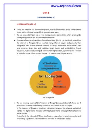
  • 1. Unit 1 FUNDAMENTALS OF IoT 1. INTRODUCTION TO IoT  Today the Internet has become ubiquitous, has touched almost every corner of the globe, and is affecting human life in unimaginable ways.  We are now entering an era of even more pervasive connectivity where a very wide variety of appliances will be connected to the web.  One year after the past edition of the Clusterbook 2012 it can be clearly statedthat the Internet of Things (IoT) has reached many different players and gainedfurther recognition. Out of the potential Internet of Things application areas,Smart Cities (and regions), Smart Car and mobility, Smart Home and assistedliving, Smart Industries, Public safety, Energy & environmental protection,Agriculture and Tourism as part of a future IoT Ecosystem (Figure 1.1) haveacquired high attention. IoT Ecosystem.  We are entering an era of the “Internet of Things” (abbreviated as IoT).There are 2 definitions: First one is defined by Vermesan and second by Pe˜na-L´opez 1. The Internet of Things as simply an interaction between the physical and digital worlds. The digital world interacts with the physical world using a plethora of sensors and actuators. 2. Another is the Internet of Things is defined as a paradigm in which computing and networking capabilities are embedded in any kind of conceivable object. www.rejinpaul.com
  • 2.  We use these capabilities to query the state of the object and to change its state if possible.  In common parlance, the Internet of Things refers to a new kind of world where almost all the devices and appliances that we use are connected to a network.  We can use them collaboratively to achieve complex tasks that require a high degree of intelligence.  For this intelligence and interconnection, IoT devices areequipped with embedded sensors, actuators, processors, andtransceivers.  IoT is not a single technology; rather it is anagglomeration of various technologies that work together intandem.  Sensors and actuators are devices, which help in interactingwith the physical environment.  The data collected by thesensors has to be stored and processed intelligently in order toderive useful inferences from it.  Note that we broadly definethe term sensor; a mobile phone or even a microwave ovencan count as a sensor as long as it provides inputs about itscurrent state (internal state + environment).  An actuator is adevice that is used to effect a change in the environment suchas the temperature controller of an air conditioner.  The storage and processing of data can be done on theedge of the network itself or in a remote server.  If any preprocessingof data is possible, then it is typically done at eitherthe sensor or some other proximate device.  The processeddata is then typically sent to a remote server.  The storageand processing capabilities of an IoT object are also restrictedby the resources available, which are often very constraineddue to limitations of size, energy, power, and computationalcapability.  As a result the main research challenge is toensure that we get the right kind of data at the desired levelof accuracy.  Along with the challenges of data collection, and handling, there are challenges in communication aswell.  The communication between IoT devices is mainlywireless because they are generally installed at geographicallydispersed locations.  The wireless channels often have high rates of distortion and are unreliable.  In this scenario reliablycommunicating data without too many retransmissions is animportant problem and thus communication technologiesare integral to the study of IoT devices.  We can directly modify the physical world through actuators or we may do something virtually. For example,we can send some information to other smart things. www.rejinpaul.com
  • 3.  The process of effecting a change in the physical world is often dependent on its state at that point of time. This is called context awareness. Each action is taken keeping in consideration the context because an application can behave differently in different contexts.  For example, a person may not like messages from his office to interrupt him when he is on vacation. Sensors, actuators, compute servers, and the communication network form the core infrastructure of an IoT framework. However, there are many software aspects that need to be considered.  First, we need a middleware that can be used to connect and manage all of these heterogeneous components. We need a lot of standardization to connect many different devices.  The Internet of Things finds various applications in health care, fitness, education, entertainment, social life, energy conservation, environment monitoring, home automation, and transport systems. 1.2 TECHNOLOGIES INVOLVED IN IOT DEVELOPMENT: INTERNET/WEB AND NETWORKING BASICS OSI MODEL  Networking technologies enable IoT devices to communicate with other devices, applications, and services running in the cloud.  The internet relies on standardized protocols to ensure communication between heterogeneous devices is secure and reliable.  Standard protocols specify rules and formats that devices use to establish and manage networks and transmit data across those networks.  Networks are built as a “stack” of technologies. A technology such as Bluetooth LE is at the bottom of the stack.  While others such as such as IPv6 technologies (which is responsible for the logical device addressing and routing of network traffic) are further up the stack. Technologies at the top of the stack are used by the applications that are running on top of those layers, such as message queuing technologies.  This article describes widely adopted technologies and standards for IoT networking. It also provides guidance for choosing one network protocol over another. It then discusses key considerations and challenges related to networking within IoT: range, bandwidth, power usage, intermittent connectivity, interoperability, and security. www.rejinpaul.com
  • 4. NETWORKING STANDARDS AND TECHNOLOGIES  The Open Systems Interconnection (OSI) model is an ISO-standard abstract model is a stack of seven protocol layers.  From the top down, they are: application, presentation, session, transport, network, data link and physical. TCP/IP, or the Internet Protocol suite, underpins the internet, and it provides a simplified concrete implementation of these layers in the OSI model. Figure 1. OSI and TCP/IP networking models The TCP/IP model includes only four layers, merging some of the OSI model layers:  Network Access & Physical Layer This TCP/IP Layer subsumes both OSI layers 1 and 2. The physical (PHY) layer (Layer 1 of OSI) governs how each device is physically connected to the network with hardware, for example with an optic cable, wires, or radio in the case of wireless network like wifi IEEE 802.11 a/b/g/n). At the link layer (Layer 2 of OSI), devices are identified by a MAC address, and protocols at this level are concerned with physical addressing, such as how switches deliver frames to devices on the network.  Internet Layer This layer maps to the OSI Layer 3 (network layer). OSI Layer 3 relates to logical addressing. Protocols at this layer define how routers deliver packets of data www.rejinpaul.com
  • 5. between source and destination hosts identified by IP addresses. IPv6 is commonly adopted for IoT device addressing.  Transport Layer The transport layer (Layer 4 in OSI) focuses on end-to-end communication and provides features such as reliability, congestion avoidance, and guaranteeing that packets will be delivered in the same order that they were sent. UDP (User Datagram protocol) is often adopted for IoT transport for performance reasons.  Application Layer The application layer (Layers 5, 6, and 7 in OSI) covers application-level messaging. HTTP/S is an example of an application layer protocol that is widely adopted across the internet. Although the TCP/IP and OSI models provide you with useful abstractions for discussing networking protocols and specific technologies that implement each protocol, some protocols don’t fit neatly into these layered models and are impractical. For example, the Transport Layer Security (TLS) protocol that implements encryption to ensure privacy and data integrity of network traffic can be considered to operate across OSI layers 4, 5, and 6. NETWORK ACCESS AND PHYSICAL LAYER IOT NETWORK TECHNOLOGIES IoT network technologies to be aware of toward the bottom of the protocol stack include cellular, Wifi, and Ethernet, as well as more specialized solutions such as LPWAN, Bluetooth Low Energy (BLE), ZigBee, NFC, and RFID. NB-IoT is becoming the standard for LPWAN networks, according to Gartner. This IoT for All article tells more about NB-IoT. The following are network technologies with brief descriptions of each:  LPWAN (Low Power Wide Area Network) is a category of technologies designed for low- power, long-range wireless communication. They are ideal for large-scale deployments of low-power IoT devices such as wireless sensors. LPWAN technologies include LoRa (LongRange physical layer protocol), Haystack, SigFox, LTE-M, and NB-IoT (Narrow-Band IoT).  Cellular The LPWAN NB-IoT and LTE-M standards address low-power, low-cost IoT communication options using existing cellular networks. NB-IoT is the newest of www.rejinpaul.com
  • 6. these standards and is focused on long-range communication between large numbers of primarily indoor devices. LTE-M and NB-IoT were developed specifically for IoT, however existing cellular technologies are also frequently adopted for long-range wireless communication. While this has included 2G (GSM) in legacy devices (and currently being phased out), CDMA (also being retired or phased out), it also includes 3G, which is rapidly being phased out with several network providers retiring all 3G devices. 4G is still active and will be until 5G becomes fully available and implemented.  Bluetooth Low Energy (BLE) BLE is a low-power version of the popular Bluetooth 2.4 GHz wireless communication protocol. It is designed for short-range (no more than 100 meters) communication, typically in a star configuration, with a single primary device that controls several secondary devices. Bluetooth operates across both layers 1 (PHY) and 2 (MAC) of the OSI model. BLE is best suited to devices that transmit low volumes of data in bursts. Devices are designed to sleep and save power when they are not transmitting data. Personal IoT devices such as wearable health and fitness trackers, often use BLE.  ZigBee ZigBee operates on 2.4GHz wireless communication spectrum. It has a longer range than BLE by up to 100 meters. It also has a slightly lower data rate (250 kbps maximum compared to 270 kbps for BLE) than BLE. ZigBee is a mesh network protocol. Unlike BLE, not all devices can sleep between bursts. Much depends on their position in the mesh and whether they need to act as routers or controllers within the mesh. ZigBee was designed for building and home automation applications. Another closely related technology to ZigBee is Z-Wave, which is also based on IEEE 802.15.4. Z-Wave was designed for home automation. It has been proprietary technology, but was recently released as a public domain specification.  NFC The near field communication (NFC) protocol is used for very small range communication (up to 4 cm), such as holding an NFC card or tag next to a reader. NFC is often used for payment systems, but also useful for check-in systems and smart labels in asset tracking.  RFID RFID stands for Radio Frequency Identification. RFID tags store identifiers and data. The tags are attached to devices and read by an RFID reader. The typical range of RFID is less than a meter. RFID tags can be active, passive, or assisted passive. Passive tags are ideal for devices without batteries, as the ID is passively www.rejinpaul.com
  • 7. read by the reader. Active tags periodically broadcast their ID, while assisted passive tags become active when RFID reader is present. Dash7 is a communication protocol that uses active RFID that is designed to be used within Industrial IoT applications for secure long-range communication. Similar to NFC, a typical use case for RFID is tracking inventory items within retail and industrial IoT applications.  Wifi Wifi is standard wireless networking based on IEEE 802.11a/b/g/n specifications. 802.11n offers the highest data throughput, but at the cost of high-power consumption, so IoT devices might only use 802.11b or g for power conservation reasons. Although wifi is adopted within many prototype and current generation IoT devices, as longer-range and lower-power solutions become more widely available, it is likely that wifi will be superseded by lower-power alternatives.  Ethernet Widely deployed for wired connectivity within local area networks, Ethernet implements the IEEE 802.3 standard. Not all IoT devices need to be stationery wireless . For example, sensor units installed within a building automation system can use wired networking technologies like Ethernet. Power line communication (PLC), an alternative hard-wired solution, uses existing electrical wiring instead of dedicated network cables. INTERNET LAYER IOT NETWORK TECHNOLOGIES Internet layer technologies (OSI Layer 3) identify and route packets of data. Technologies commonly adopted for IoT are related to this layer, and include IPv6, 6LoWPAN, and RPL.  IPv6 At the Internet layer, devices are identified by IP addresses. IPv6 is typically used for IoT applications over legacy IPv4 addressing. IPv4 is limited to 32-bit addresses, which only provide around 4.3 billion addresses in total, which is less than the current number of IoT devices that are connected, while IPv6 uses 128 bits, and so provides 2 128 addresses (around 3.4 × 10 38 or 340 billion billion billion billion) addresses. In practice, not all IoT devices need public addresses. Of the tens of billions of devices expected to connect via the IoT over the next few years, many will be deployed in private networks that use private address ranges and only communicate out to other devices or services on external networks by using gateways.  6LoWPAN The IPv6 Low Power Wireless Personal Area Network (6LoWPAN) standard allows IPv6 to be used over 802.15.4 wireless networks. 6LoWPAN is often used for wireless sensor networks, and the Thread protocol for home automation devices also runs over 6LoWPAN. www.rejinpaul.com
  • 8.  RPL The Internet Layer also covers routing. IPv6 Routing Protocol for Low-Power and Lossy Networks (RPL) is designed for routing IPv6 traffic over low-power networks like those networks implemented over 6LoWPAN. RPL (pronounced “ripple”) is designed for routing packets within constrained networks such as wireless sensor networks, where not all devices are reachable at all times and there are high or unpredictable amounts of packet loss. RPL can compute the optimal path by building up a graph of the nodes in the network based on dynamic metrics and constraints like minimizing energy consumption or latency. APPLICATION LAYER IOT NETWORK TECHNOLOGIES HTTP and HTTPS are ubiquitous across internet applications, which is true also within IoT, with RESTful HTTP and HTTPS interfaces widely deployed. CoAP (Constrained Application Protocol) is like a lightweight HTTP that is often used in combination with 6LoWPAN over UDP. Messaging protocols like MQTT, AMQP, and XMPP are also frequently used within IoT applications:  MQTT Message Queue Telemetry Transport (MQTT) is a publish/subscribe-based messaging protocol that was designed for use in low bandwidth situations, particularly for sensors and mobile devices on unreliable networks.  AMQP Advanced Message Queuing Protocol (AMQP) is an open standard messaging protocol that is used for message-oriented middleware. Most notably, AMQP is implemented by RabbitMQ.  XMPP The Extensible Messaging and Presence Protocol (XMPP) was originally designed for real-time human-to-human communication including instant messaging. This protocol has been adapted for machine-to-machine (M2M) communication to implement lightweight middleware and for routing XML data. XMPP is primarily used with smart appliances. Your choice of technologies at this layer will depend on the specific application requirements of your IoT project. For example, for a budget home automation system that involves several sensors, MQTT would be a good choice as it is great for implementing messaging on devices without much storage or processing power because the protocol is simple and lightweight to implement. www.rejinpaul.com
  • 9. IOT NETWORKING CONSIDERATIONS AND CHALLENGES When you consider which networking technologies to adopt within your IoT application, be mindful of the following constraints:  Range  Bandwidth  Power usage  Intermittent connectivity  Interoperability  Security Range Networks can be described in terms of the distances over which data is typically transmitted by the IoT devices attached to the network:  PAN(PersonalAreaNetwork) PAN is short-range, where distances can be measured in meters, such as a wearable fitness tracker device that communicates with an app on a cell phone over BLE.  LAN(LocalAreaNetwork) LAN is short- to medium-range, where distances can be up to hundreds of meters, such as home automation or sensors that are installed within a factory production line that communicate over wifi with a gateway device that is installed within the same building.  MAN (Metropolitan Area Network) MAN is long-range (city wide), where distances are measured up to a few kilometers, such as smart parking sensors installed throughout a city that are connected in a mesh network topology.  WAN (Wide Area Network) WAN is long-range, where distances can be measured in kilometers, such as agricultural sensors that are installed across a large farm or ranch that are used to monitor micro-climate environmental conditions across the property. Your network should retrieve data from the IoT devices and transmit to its intended destination. Select a network protocol that matches the range is required. For example, do not choose BLE for a WAN application to operate over a range of several kilometers. If transmitting data over the required range presents a challenge, consider edge computing. Edge computing analyzes data directly from the devices rather than from a distant data center or elsewhere. www.rejinpaul.com
  • 10. Bandwidth Bandwidth is the amount of data that can be transmitted per unit of time. It limits the rate at which data can be collected from IoT devices and transmitted upstream. Bandwidth is affected by many factors, which include:  The volume of data each device gathers and transmits  The number of devices deployed  Whether data is being sent as a constant stream or in intermittent bursts, and if any peak periods are notable The packet size of the networking protocol should match up with the volume of data typically transmitted. It is inefficient to send packets padded with empty data. In contrast, there are overheads in splitting larger chunks of data up across too many small packets. Data transmission rates are not always symmetrical (that is, upload rates might be slower than download rates). So, if there is two-way communication between devices, data transmission needs to be factored in. Wireless and cellular networks are traditionally low bandwidth, so consider whether a wireless technology is the right choice for high-volume applications. Consider whether all raw data must be transmitted. A possible solution is to capture less data by sampling less frequently. Thus, you’ll capture fewer variables and may filter data from the device to drop insignificant data. If you aggregate the data before you transmit it, you reduce the volume of data transmitted. But this process affects flexibility and granularity in the upstream analysis. Aggregation and bursting are not always suitable for time-sensitive or latency-sensitive data. All of these techniques increase the data processing and storage requirements for the IoT device. Power usage Transmitting data from a device consumes power. Transmitting data over long ranges requires more power than over a short range. You must consider the power source – such as a battery, solar cell, or capacitor – of a device and its total lifecycle. A long and enduring lifecycle will not only provide greater reliability but reduce operating cost. Steps may be taken to help achieve longer power supply lifecycles. For example, to prolong the battery life, you can put the device into sleep mode whenever it is idle. Another best practice is to model the energy consumption of the device under different loads and different network conditions to ensure that the device’s power supply and storage capacity matches with the power that is required to transmit the necessary data by using the networking technologies that you adopted. www.rejinpaul.com
  • 11. Intermittent connectivity IoT devices aren’t always connected. In some cases, devices are designed to connect periodically. However, sometimes an unreliable network might cause devices to drop off due to connectivity issues. Sometimes quality of service issues, such as dealing with interference or channel contention on a wireless network using a shared spectrum. Designs should incorporate intermittent connectivity and seek any available solutions to provide uninterrupted service, should that be a critical factor for IoT landscape design. Interoperability Devices work with other devices, equipment, systems, and technology; they are interoperable. With so many different devices connecting to the IoT, interoperability can be a challenge. Adopting standard protocols has been a traditional approach for maintaining interoperability on the Internet. Standards are agreed upon by industry participants and avoid multiple different designs and directions. With proper standards, and participants who agree to them, incompatibility issues, hence interoperability issues may be avoided. However, for the IoT, standardization processes sometimes struggle to keep up with innovation and change. They are written and released based on upcoming versions of standards that are still subject to change. Consider the ecosystem around the technologies: Are they widely adopted? Are they open versus proprietary? How many implementations are available? Using these questions to plan your IoT networks help plan better interoperability for a more robust IoT network. Security Security is a priority. Selection of networking technologies that implement end-to-end security, including authentication, encryption, and open port protection is crucial. IEEE 802.15.4 includes a security model that provides security features that include access control, message integrity, message confidentiality, and replay protection, which are implemented by technologies based on this standard such as ZigBee. Consider the following factors in shaping a secure and safe IoT network:  Authentication Adopt secure protocols to support authentication for devices, gateways, users, services, and applications. Consider using adopting the X.509 standard for device authentication. www.rejinpaul.com
  • 12.  Encryption If you are using wifi, use Wireless Protected Access 2 (WPA2) for wireless network encryption. You may also adopt a Private Pre-Shared Key (PPSK) approach. To ensure privacy and data integrity for communication between applications, be sure to adopt TLS or Datagram Transport-Layer Security (DTLS), which is based on TLS, but adapted for unreliable connections that run over UDP. TLS encrypts application data and ensures its integrity.  Port protection Port protection ensures that only the ports required for communication with the gateway or upstream applications or services remain open to external connections. All other ports should be disabled or protected by firewalls. Device ports might be exposed when exploiting Universal Plug and Play (UPnP) vulnerabilities. Thus, UPnP should be disabled on the router. The IoT World Forum (IoTWF) Standardized Architecture In 2014 the IoTWF architectural committee (led by Cisco, IBM, Rockwell Automation, and others)published a seven-layer IoT architectural reference model. While various IoT reference models exist, theone put forth by the IoT World Forum offers a clean, simplified perspective on IoT and includes edgecomputing, data storage, and access. It provides a succinct way of visualizing IoT from a technicalperspective. Each of the seven layers is broken down into specific functions, and security encompassesthe entire model. Figure belowdetails the IoT Reference Model published by the IoTWF. As shown in Figure 2-2, the IoT Reference Model defines a set of levels with control flowing from thecenter (this could be either a cloud service or a dedicated data center), to the edge, www.rejinpaul.com
  • 13. which includessensors, devices, machines, and other types of intelligent end nodes. In general, data travels up the stack,originating from the edge, and goes northbound to the center. Using this reference model, we are able toachieve the following:  Decompose the IoT problem into smaller parts  Identify different technologies at each layer and how they relate to one another  Define a system in which different parts can be provided by different vendors  Have a process of defining interfaces that leads to interoperability  Define a tiered security model that is enforced at the transition points between levels The following sections look more closely at each of the seven layers of the IoT Reference Model. Layer 1: Physical Devices and Controllers Layer The first layer of the IoT Reference Model is the physical devices and controllers layer. This layer is hometo the “things” in the Internet of Things, including the various endpoint devices and sensors that send andreceive information. The size of these “things” can range from almost microscopic sensors to giantmachines in a factory. Their primary function is generating data and being capable of being queriedand/or controlled over a network. Layer 2: Connectivity Layer In the second layer of the IoT Reference Model, the focus is on connectivity. The most important functionof this IoT layer is the reliable and timely transmission of data. More specifically, this includestransmissions between Layer 1 devices and the network and between the network and informationprocessing that occurs at Layer 3 (the edge computing layer).As you may notice, the connectivity layer encompasses all networking elements of IoT and doesn’t reallydistinguish between the last-mile network (the network between the sensor/endpoint and the IoT gateway,discussed later in this chapter), gateway, and backhaul networks. Functions of the connectivity layer aredetailed in Figure 2-3. www.rejinpaul.com
  • 14. Layer 3: Edge Computing Layer Edge computing is the role of Layer 3. Edge computing is often referred to as the “fog” layer and isdiscussed in the section “Fog Computing,” later in this chapter. At this layer, the emphasis is on datareduction and converting network data flows into information that is ready for storage and processing byhigher layers. One of the basic principles of this reference model is that information processing is initiated as early and as close to the edge of the network as possible. Figure 2-4 highlights the functions handledby Layer 3 of the IoT Reference Model. Another important function that occurs at Layer 3 is the evaluation of data to see if it can be filtered oraggregated before being sent to a higher layer. This also allows for data to be reformatted or decoded,making additional processing by other systems easier. Thus, a critical function is assessing the data to seeif predefined thresholds are crossed and any action or alerts need to be sent. Upper Layers: Layers 4–7 The upper layers deal with handling and processing the IoT data generated by the bottom layer. For thesake of completeness, Layers 4–7 of the IoT Reference Model are summarized in Table 2-2. www.rejinpaul.com
  • 15. M2M Communication Machine-to-machine communication, or M2M, is exactly as it sounds: two machines “communicating,” or exchanging data, without human interfacing or interaction. This includes serial connection, powerline connection (PLC), or wireless communications in the industrial Internet of Things (IoT). Switching over to wireless has made M2M communication much easier and enabled more applications to be connected. In general, when someone says M2M communication, they often are referring to cellular communication for embedded devices. Examples of M2M communication in this case would be vending machines sending out inventory information or ATM machines getting authorization to despense cash. As businesses have realized the value of M2M, it has taken on a new name: the Internet of Things (IoT). IoT and M2M have similar promises: to fundamentally change the way the world operates. Just like IoT, M2M allows virtually any sensor to communicate, which opens up the possibility of systems monitoring themselves and automatically responding to changes in the environment, with a much reduced need for human involvement. M2M and IoT are almost synonymous—the exception is IoT (the newer term) typically refers to wireless communications, whereas M2M can refer to any two machines—wired or wireless—communicating with one another. www.rejinpaul.com
  • 16. Traditionally, M2M focused on “industrial telematics,” which is a fancy way of explaining data transfer for some commercial benefit. But many original uses of M2M still stand today, like smart meters. Wireless M2M has been dominated by cellular since it came out in the mid-2000’s with 2G cell networks. Because of this, the cellular market has tried to brand M2M as an inherently cellular thing by offering M2M data plans. But cellular M2M is only one subsection of the market, and it shouldn’t be thought of as a cellular-only area. How M2M Works As previously stated, machine-to-machine communication makes the Internet of Things possible. According to Forbes, M2M is among the fastest-growing types of connected device technologies in the market right now, largely because M2M technologies can connect millions of devices within a single network. The range of connected devices includes anything from vending machines to medical equipment to vehicles to buildings. Virtually anything that houses sensor or control technology can be connected to some sort of wireless network. This sounds complex, but the driving thought behind the idea is quite simple. Essentially, M2M networks are very similar to LAN or WAN networks, but are exclusively used to allow machines, sensors, and controls, to communicate. These devices feed information they collect back to other devices in the network. This process allows a human (or an intelligent control unit) to assess what is going on across the whole network and issue appropriate instructions to member devices. M2M Applications The possibilities in the realm of M2M can be seen in four major use cases, which we’ve detailed below: 1. MANUFACTURING Every manufacturing environment—whether it’s food processing or general product manufacturing—relies on technology to ensure costs are managed properly and processes are executed efficiently. Automating manufacturing processes within such a fast-paced environment is expected to improve processes even more. In the manufacturing world, this could involve highly automated equipment maintenance and safety procedures. For example, M2M tools allow business owners to be alerted on their smartphones when an important piece of equipment needs servicing, so they can address issues as quickly as they arise. Sophisticated networks of sensors connected to the Internet could even order replacement parts automatically. www.rejinpaul.com
  • 17. 2. HOME APPLIANCES IoT already affects home appliance connectivity through platforms like Nest. However, M2M is expected to take home-based IoT to the next level. Manufacturers like LG and Samsung are already slowly unveiling smart home appliances to help ensure a higher quality of life for occupants. For example, an M2M-capable washing machine could send alerts to the owners’ smart devices once it finishes washing or drying, and a smart refrigerator could automatically order groceries from Amazon once its inventory is depleted. There are many more examples of home automation that can potentially improve quality of life for residents, including systems that allow members of the household to remotely control HVAC systems using their mobile devices. In situations where a homeowner decides to leave work early, he or she could contact the home heating system before leaving work to make sure the temperature at home will be comfortable upon arrival. 3. HEALTHCARE DEVICE MANAGEMENT One of the biggest opportunities for M2M technology is in the realm of health care. With M2M technology, hospitals can automate processes to ensure the highest levels of treatment. Using devices that can react faster than a human healthcare professional in an emergency situation make this possible. For instance, when a patient’s vital signs drop below normal, an M2M-connected life support device could automatically administer oxygen and additional care until a healthcare professional arrives on the scene. M2M also allows patients to be monitored in their own homes instead of in hospitals or care centers. For example, devices that track a frail or elderly person’s normal movements can detect when he or she has had a fall and alert a healthcare worker to the situation. 4. SMART UTILITY MANAGEMENT In the new age of energy efficiency, automation will quickly become the new normal. As energy companies look for new ways to automate the metering process, M2M comes to the rescue, helping energy companies automatically gather energy consumption data, so they can accurately bill customers. Smart meters can track how much energy a household or business uses and automatically alert the energy company, which supplants sending out an employee to read the meter or requiring the customer to provide a reading. This is even more important as utilities move toward more dynamic pricing models, charging consumers more for energy usage during peak times. A few key analysts predict that soon, every object or device will need to be able to connect to the cloud. This is a bold but seemingly accurate statement. As more consumers, users, and business owners demand deeper connectivity, technology will need to be continually www.rejinpaul.com
  • 18. equipped to meet the needs and challenges of tomorrow. This will empower a wide range of highly automated processes, from equipment repairs and firmware upgrades to system diagnostics, data retrieval, and analysis. Information will be delivered to users, engineers, data scientists, and key decision-makers in real time, and it will eliminate the need for guesswork. The Value Of M2M Growth in the M2M and IoT markets has been growing rapidly, and according to many reports, growth will continue. Strategy Analytics believes that low power, wide-area network (LPWAN) connections will grow from 11 million in 2014 to 5 billion in 2022. And IDC says the market for worldwide IoT solutions will go from $1.9 trillion in 2013 to $7.1 trillion in 2020. Many big cell operators, like AT&T and Verizon, see this potential and are rolling out their own M2M platforms. Intel, PTC, and Wipro are are all marketing heavily in M2M and working to take advantage of this major industry growth spurt. But there is still a great opportunity for new technology companies to engage in highly automated solutions to help streamline processes in nearly any type of industry. We’re certain we’ll see a huge influx of companies who begin to innovate in this area in the next five years. However, as the cost of M2M communication continues to decrease, companies must determine how they will create value for businesses and customers. In our mind, the opportunity and value for M2M doesn’t lie in the more traditional layers of the communication world. Cell carriers and hardware manufacturers, for example, are beginning to look into full-stack offerings that enable M2M and IoT product development. We strongly believe value lies in the application side of things, and the growth in this industry will be driven by smart applications from this point forward. Companies shouldn’t think about IoT or M2M for the sake of IoT or M2M. Instead, they should focus on optimizing their business models or providing new value for their customers. For example, if you’re a logistics company like FedEx or UPS, you have obvious choices for automated logistics decisions made by machines. But if you’re a retailer, the transition to automation may not be as obvious. It’s one thing to think of a “cool” automated process—say, creating advertising that is automatically tied to a specific customer through the use of M2M technology—but before you move forward with the process, you have to consider the value you’re getting out of it. How much does it cost to implement? Will any company considering a move into the IoT space needs to understand what its business model is, how it will make money, and how it will provide value for customers or internal processes. www.rejinpaul.com
  • 19. Architecture of IoT Figure below has three layers, namely, the perception, network, and application layers. (i) The perception layer is the physical layer, which has sensors for sensing and gathering information about the environment. It senses some physical parameters or identifies other smart objects in the environment. (ii) The network layer is responsible for connecting to other smart things, network devices, and servers. Its features are also used for transmitting and processing sensor data. (iii) The application layer is responsible for delivering application specific services to the user. It defines various applications in which the Internet of Things can be deployed, for example, smart homes, smart cities, and smart health. The three-layer architecture defines the main idea of the Internet of Things, but it is not sufficient for research on IoT because research often focuses on finer aspects of the Internet of Things. That is why, we have many more layered architectures proposed in the literature. One is the fivelayer architecture, which additionally includes the processing and business layers [3–6]. The five layers are perception, transport, processing, application, and business layers (see Figure 1). The role of the perception and application layers is the same as the architecture with three layers. We outline the function of the remaining three layers. (i) The transport layer transfers the sensor data from the perception layer to the processing layer and vice versa through networks such as wireless, 3G, LAN, Bluetooth, RFID, and NFC. (ii) The processing layer is also known as the middleware layer. It stores, analyzes, and processes huge amounts of data that comes from the transport layer. It can manage and provide a diverse set of services to the www.rejinpaul.com
  • 20. lower layers. It employs many technologies such as databases, cloud computing, and big data processing modules. (iii) The business layer manages the whole IoT system, including applications, business and profit models, and users’ privacy. The business layer is out of the scope of this paper. Hence, we do not discuss it further. Core IoT Functional Stack The IoT network must be designed to support its unique requirements and constraints. This section provides an overview of the full networking stack, from sensors all the way to the applications layer. The Core IoT Functional Stack IoT networks are built around the concept of “things,” or smart objects performing functions and delivering new connected services. These objects are “smart” because they use a combination of contextual information and configured goals to perform actions. These actions can be self-contained (that is, the smart object does not rely on external systems for its actions); however, in most cases, the “thing” interacts with an external system to report information that the smart object collects, to exchange with other objects, or to interact with a management platform. In this case, the management platform can be used to process data collected from the smart object and also guide the behavior of the smart object. From an architectural standpoint, several components have to work together for an IoT network to be operational: “Things” layer: At this layer, the physical devices need to fit the constraints of the environment in which they are deployed while still being able to provide the information needed. Communications network layer: When smart objects are not self-contained, they need to communicate with an external system. In many cases, this communication uses a wireless technology. This layer has four sublayers: Access network sublayer: The last mile of the IoT network is the access network. This is typically made up of wireless technologies such as 802.11ah, 802.15.4g, and LoRa. The sensors connected to the access network may also be wired. Gateways and backhaul network sublayer: A common communication system organizes multiple smart objects in a given area around a common gateway. The gateway communicates directly with the smart objects. The role of the gateway is to forward the collected information through a longer- range medium (called the backhaul) to a headend central station where the information is processed. This information exchange is a Layer 7 (application) function, which is the reason this object is called a gateway. On IP networks, this gateway also forwards packets from one IP network to another, and it therefore acts as a router. Network transport sublayer: For communication to be successful, network and transport layer protocols such as IP and UDP must be implemented to support the variety of devices to connect and media to use. IoT network management sublayer: Additional protocols must be in place to allow the headend applications to exchange data with the sensors. Examples include CoAP and MQTT. www.rejinpaul.com
  • 21. Application and analytics layer: At the upper layer, an application needs to process the collected data, not only to control the smart objects when necessary, but to make intelligent decision based on the information collected and, in turn, instruct the “things” or other systems to adapt to the analyzed conditions and change their behaviors or parameters. The following sections examine these elements and help you architect your IoT communication network. Layer 1: Things: Sensors and Actuators Layer Most IoT networks start from the object, or “thing,” that needs to be connected.From an architectural standpoint, the variety of smart object types, shapes, and needs drive the variety of IoT protocols and architectures. There are myriad ways to classify smart objects. One architectural classification could be:  Battery-powered or power-connected: This classification is based on whether the object carries its own energy supply or receives continuous power from an external power source. Battery- powered things can be moved more easily than line- powered objects. However, batteries limit the lifetime and amount of energy that the object is allowed to consume, thus driving transmission range and frequency.  Mobile or static: This classification is based on whether the “thing” should move or always stay at the same location. A sensor may be mobile because it is moved from one object to another (for example, a viscosity sensor moved from batch to batch in a chemical plant) or because it is attached to a moving object (for example, a location sensor on moving goods in a warehouse or factory floor). The frequency of the movement may also vary, from occasional to permanent. The range of mobility (from a few inches to miles away) often drives the possible power source.  Low or high reporting frequency: This classification is based on how often the object should report monitored parameters. A rust sensor may report values once a month. A motion sensor may report acceleration several hundred times per second. Higher frequencies drive higher energy consumption, which may create constraints on the possible power source (and therefore the object mobility) and the transmission range.  Simple or rich data: This classification is based on the quantity of data exchanged at each report cycle. A humidity sensor in a field may report a simple daily index value (on a binary scale from 0 to 255), while an engine sensor may report hundreds of parameters, from temperature to pressure, gas velocity, compression speed, carbon index, and many others. Richer data typically drives higher power consumption. This classification is often combined with the previous to determine the object data throughput (low throughput to high throughput). You may want to keep in mind that throughput is a combined metric. A medium-throughput object may send simple data at rather high frequency (in which case the flow structure looks www.rejinpaul.com
  • 22. continuous), or may send rich data at rather low frequency (in which case the flow structure looks bursty).  Report range: This classification is based on the distance at which the gateway is located. For example, for your fitness band to communicate with your phone, it needs to be located a few meters away at most. The assumption is that your phone needs to be at visual distance for you to consult the reported data on the phone screen. If the phone is far away, you typically do not use it, and reporting data from the band to the phone is not necessary. By contrast, a moisture sensor in the asphalt of a road may need to communicate with its reader several hundred meters or even kilometers away.  Object density per cell: This classification is based on the number of smart objects (with a similar need to communicate) over a given area, connected to the same gateway. An oil pipeline may utilize a single sensor at key locations every few miles. By contrast, telescopes like the SETI Colossus telescope at the Whipple Observatory deploy hundreds, and sometimes thousands, of mirrors over a small area, each with multiple gyroscopes, gravity, and vibration sensors. Layer 2: Communications Network Layer Once you have determined the influence of the smart object form factor over its transmission capabilities (transmission range, data volume and frequency, sensor density and mobility), you are ready to connect the object and communicate. Compute and network assets used in IoT can be very different from those in IT environments. The difference in the physical form factors between devices used by IT and OT is obvious even to the most casual of observers. What typically drives this is the physical environment in which the devices are deployed. What may not be as inherently obvious, however, is their operational differences. The operational differences must be understood in order to apply the correct handling to secure the target assets. Temperature variances are an easily understood metric. The cause for the variance is easily attributed to external weather forces and internal operating conditions. Remote external locations, such as those associated with mineral extraction or pipeline equipment can span from the heat of the Arabian Gulf to the cold of the Alaskan North Slope. Controls near the furnaces of a steel mill obviously require heat tolerance, and controls for cold food storage require the opposite. In some cases, these controls must handle extreme fluctuations as well. These extremes can be seen within a single deployment. For example, portions of the Tehachapi, California, wind farms are located in the Mojave Desert, while others are at an altitude of 1800 m in the surrounding mountains. As you can imagine, the wide variance in temperature takes a special piece of hardware that is capable of withstanding such harsh environments. Humidity fluctuations can impact the long- term success of a system as well. Well heads residing in the delta of the Niger River www.rejinpaul.com
  • 23. will see very different conditions from those in the middle of the Arabian Desert. In some conditions, the systems could be exposed to direct liquid contact such as may be found with outdoor wireless devices or marine condition deployments. Less obvious are the operating extremes related to kinetic forces. Shock and vibration needs vary based on the deployment scenario. In some cases, the focus is on low- amplitude but constant vibrations, as may be expected on a bushing-mounted manufacturing system. In other cases, it could be a sudden acceleration or deceleration, such as may be experienced in peak ground acceleration of an earthquake or an impact on a mobile system such as high-speed rail or heavy-duty earth moving equipment. Solid particulates can also impact the gear. Most IT environments must contend with dust build-up that can become highly concentrated due to the effect of cooling fans. In less-controlled IT environments, that phenomenon can be accelerated due to higher concentrations of particulates. A deterrent to particulate build-up is to use fanless cooling, which necessitates a higher surface area, as is the case with heat transfer fins. Hazardous location design may also cause corrosive impact to the equipment. Caustic materials can impact connections over which power or communications travel. Furthermore, they can result in reduced thermal efficiency by potentially coating the heat transfer surfaces. In some scenarios, the concern is not how the environment can impact the equipment but how the equipment can impact the environment. For example, in a scenario in which volatile gases may be present, spark suppression is a critical design criterion. There is another class of device differentiators related to the external connectivity of the device for mounting or industrial function. Device mounting is one obvious difference between OT and IT environments. While there are rack mount environments in some industrial spaces, they are more frequently found among IT type assets. Within industrial environments, many compute and communication assets are placed within an enclosed space, such as a control cabinet where they will be vertically mounted on a DIN (Deutsches Institut für Normung) rail inside. In other scenarios, the devices might be mounted horizontally directly on a wall or on a fence. In contrast to most IT-based systems, industrial compute systems often transmit their state or receive inputs from external devices through an alarm channel. These may drive an indicator light (stack lights) to display the status of a process element from afar. This same element can also receive inputs to initiate actions within the system itself. Power supplies in OT systems are also frequently different from those commonly seen on standard IT equipment. A wider range of power variations are common attributes of industrial compute components. DC power sources are also common in many environments. Given the criticality of many systems, it is often required that redundant power supplies be built into the device itself. Extraneous power supplies, especially those not inherently mounted, are frowned upon, given the potential for accidental unplugging. In some utility cases, the system must be able to handle brief power outages and still continue to operate. www.rejinpaul.com
  • 24.  Access Network Sublayer There is a direct relationship between the IoT network technology you choose and the type of connectivity topology this technology allows. Each technology was designed with a certain number of use cases in mind (what to connect, where to connect, how much data to transport at what interval and over what distance). These use cases determined the frequency band that was expected to be most suitable, the frame structure matching the expected data pattern (packet size and communication intervals), and the possible topologies that these use cases illustrate. As IoT continues to grow exponentially, you will encounter a wide variety of applications and special use cases. For each of them, an access technology will be required. IoT sometimes reuses existing access technologies whose characteristics match more or less closely the IoT use case requirements. Whereas some access technologies were developed specifically for IoT use cases, others were not. One key parameter determining the choice of access technology is the range between the smart object and the information collector. Figure 2-9 lists some access technologies you may encounter in the IoT world and the expected transmission distances. PAN (personal area network): Scale of a few meters. This is the personal space around a person. A common wireless technology for this scale is Bluetooth. HAN (home area network): Scale of a few tens of meters. At this scale, common wireless technologies for IoT include ZigBee and Bluetooth Low Energy (BLE). NAN (neighborhood area network): Scale of a few hundreds of meters. The term NAN is often used to refer to a group of house units from which data is collected. FAN (field area network): Scale of several tens of meters to several hundred meters. FAN typically refers to an outdoor area larger than a single group of house units. The FAN is often seen as “open space” (and therefore not secured and not controlled). A FAN is sometimes viewed as a group of NANs, but some verticals see the FAN as a group of HANs or a group of smaller outdoor cells. As you can see, FAN and NAN may sometimes be used interchangeably. In most cases, the vertical context is clear enough to determine the grouping hierarchy. LAN (local area network): Scale of up to 100 m. This term is very common in networking, and it is therefore also commonly used in the IoT space when standard networking technologies (such as Ethernet or IEEE 802.11) are used. Other networking classifications, such as MAN (metropolitan area network, with a range of up to a few kilometers) and WAN (wide area network, with a range of more than a few kilometers), are also commonly used. www.rejinpaul.com
  • 25. Network Transport Sublayer The previous section describes a hierarchical communication architecture in which a series of smart objects report to a gateway that conveys the reported data over another medium and up to a central station. However, practical implementations are often flexible, with multiple transversal communication paths. For example, consider the case of IoT for the energy grid. Your house may have a meter that reports the energy consumption to a gateway over a wireless technology. Other houses in your neighborhood (NAN) make the same report, likely to one or several gateways. The data to be transported is small and the interval is large (for example, four times per hour), resulting in a low-mobility, lowthroughput type of data structure, with transmission distances up to a mile. Several technologies (such as 802.11ah, 802.15.4, or LPWA) can be used for this collection segment. Other neighborhoods may also connect the same way, thus forming a FAN. IoT Network Management Sublayer IP, TCP, and UDP bring connectivity to IoT networks. Upper-layer protocols need to take care of data transmission between the smart objects and other systems. Multiple protocols have been leveraged or created to solve IoT data communication problems. Some networks rely on a push model (that is, a sensor reports at a regular interval or based on a local trigger), whereas others rely on a pull model (that is, an application queries the sensor over the network), and multiple hybrid approaches are also possible. Layer 3: Applications and Analytics Layer Once connected to a network, your smart objects exchange information with other systems. As soon as your IoT network spans more than a few sensors, the power of the Internet of Things appears in the applications that make use of the information exchanged with the smart objects. Analytics Versus Control Applications Multiple applications can help increase the efficiency of an IoT network. Each application collects data and provides a range of functions based on analyzing the collected data. It can be difficult to compare the features offered. Chapter 7, “Data and Analytics for IoT,” provides an in-depth analysis of the various application families. From an architectural standpoint, one basic classification can be as follows: Analytics application: This type of application collects data from multiple smart objects, processes the collected data, and displays information resulting from the data that was processed. The display can be about any aspect of the IoT network, from historical reports, statistics, or trends to individual system states. The important aspect is that the application processes the data to convey a view of the network that cannot be obtained from solely looking at the information displayed by a single www.rejinpaul.com
  • 26. smart object. Control application: This type of application controls the behavior of the smart object or the behavior of an object related to the smart object. For example, a pressure sensor may be connected to a pump. A control application increases the pump speed when the connected sensor detects a drop in pressure. Control applications are very useful for controlling complex aspects of an IoT network with a logic that cannot be programmed inside a single IoT object, either because the configured changes are too complex to fit into the local system or because the configured changes rely on parameters that include elements outside the IoT object. Fog Computing The solution to the challenges mentioned in the previous section is to distribute data management throughout the IoT system, as close to the edge of the IP network as possible. The best-known embodiment of edge services in IoT is fog computing. Any device with computing, storage, and network connectivity can be a fog node. Examples include industrial controllers, switches, routers, embedded servers, and IoT gateways. Analyzing IoT data close to where it is collected minimizes latency, offloads gigabytes of network traffic from the core network, and keeps sensitive data inside the local network. Fog services are typically accomplished very close to the edge device, sitting as close to the IoT endpoints as possible. One significant advantage of this is that the fog www.rejinpaul.com
  • 27. node has contextual awareness of the sensors it is managing because of its geographic proximity to those sensors. For example, there might be a fog router on an oil derrick that is monitoring all the sensor activity at that location. Because the fog node is able to analyze information from all the sensors on that derrick, it can provide contextual analysis of the messages it is receiving and may decide to send back only the relevant information over the backhaul network to the cloud. In this way, it is performing distributed analytics such that the volume of data sent upstream is greatly reduced and is much more useful to application and analytics servers residing in the cloud. The defining characteristic of fog computing are as follows: Contextual location awareness and low latency: The fog node sits as close to the IoT endpoint as possible to deliver distributed computing. Geographic distribution: In sharp contrast to the more centralized cloud, the services and applications targeted by the fog nodes demand widely distributed deployments. Deployment near IoT endpoints: Fog nodes are typically deployed in the presence of a large number of IoT endpoints. For example, typical metering deployments often see 3000 to 4000 nodes per gateway router, which also functions as the fog computing node. Wireless communication between the fog and the IoT endpoint: Although it is possible to connect wired nodes, the advantages of fog are greatest when dealing with a large number of endpoints, and wireless access is the easiest way to achieve such scale. Use for real-time interactions: Important fog applications involve real-time interactions rather than batch processing. Preprocessing of data in the fog nodes allows upper-layer applications to perform batch processing on a subset of the data. Edge Computing Fog computing solutions are being adopted by many industries, and efforts to develop distributed applications and analytics tools are being introduced at an accelerating pace. The natural place for a fog node is in the network device that sits closest to the IoT endpoints, and these nodes are typically spread throughout an IoT network. However, in recent years, the concept of IoT computing has been pushed even further to the edge, and in some cases it now resides directly in the sensors and IoT devices. www.rejinpaul.com
  • 28. Functional blocks of an IoT ecosystem IoTdon’t exist in a void. A lone sensor isn’t really good for anything, nor is a bunch of them, for that matter, unless they are all connected to one another and to platforms that generate data for further use. This is what we call an Internet of Things (IoT) ecosystem – a broad network of connected and interdependent devices and technologies that are applied by specialists towards a specific goal, such as the creation of a smart city. Obviously, there are limitless applications to the IoT and therefore we can speak of endless coexisting IoT ecosystems. But if you boil what is happening in the ecosystem down to the bare essentials, you will come up with a simple schema: a device collects data and sends it across the network to a platform that aggregates the data for future use by the agent. And so we have the key components to an IoT ecosystem: devices, networks, platforms, and agents. Let’s discuss them in more detail. Four things form basic building blocks of the IoT system –sensors, processors, gateways, applications. Each of these nodes has to have its own characteristics in order to form an useful IoT system. www.rejinpaul.com
  • 29. Figure 1: Simplified block diagram of the basic building blocks of the IoT Sensors:  These form the front end of the IoT devices. These are the so-called “Things” of the system. Their main purpose is to collect data from its surroundings (sensors) or give out data to its surrounding (actuators).  These have to be uniquely identifiable devices with a unique IP address so that they can be easily identifiable over a large network.  These have to be active in nature which means that they should be able to collect real-time data. These can either work on their own (autonomous in nature) or can be made to work by the user depending on their needs (user-controlled).  Examples of sensors are gas sensor, water quality sensor, moisture sensor, etc. Processors:  Processors are the brain of the IoT system. Their main function is to process the data captured by the sensors and process them so as to extract the valuable data from the enormous amount of raw data collected. In a word, we can say that it gives intelligence to the data.  Processors mostly work on real-time basis and can be easily controlled by applications. These are also responsible for securing the data – that is performing encryption and decryption of data.  Embedded hardware devices, microcontroller, etc are the ones that process the data because they have processors attached to it. Gateways:  Gateways are responsible for routing the processed data and send it to proper locations for its (data) proper utilization.  In other words, we can say that gateway helps in to and fro communication of the data. It provides network connectivity to the data. Network connectivity is essential for any IoT system to communicate.  LAN, WAN, PAN, etc are examples of network gateways. www.rejinpaul.com
  • 30. Applications:  Applications form another end of an IoT system. Applications are essential for proper utilization of all the data collected.  These cloud-based applications which are responsible for rendering the effective meaning to the data collected. Applications are controlled by users and are a delivery point of particular services.  Examples of applications are home automation apps, security systems, industrial control hub, etc. IoT devices As we said earlier, there are many scenarios in which IoT can be employed and they all require different devices. Here, at the most basic level, we can speak of sensors (i.e. devices that sense things, such as temperature, motion, particles, etc.) and actuators (i.e. devices that act on things, such as switches or rotors). Rarely, though, will a smart solution make do with just one type of an IoT sensor or an actuator. If you think of a smart surgical robot, for example, it will require hundreds, if not thousands, of components that measure different parameters and act accordingly. But even apparently less complicated solutions aren’t truly that easy. Consider running a smart farm – for a plant to grow, it’s not just a matter of measuring the humidity of the soil, but also its fertility; it’s also a matter of providing proper irrigation based on insolation, and much more. So you need not just one, but many sensors and actuators that all have to work together. When speaking of devices essential for the IoT ecosystem, one cannot forget about IoT gateways. They are a piece of hardware that is capable of “translating” and facilitating the essential connection between devices or between devices and the network and work as a kind of relay for the two. Which brings us to the next element of our puzzle… www.rejinpaul.com
  • 31. Networks Based on what you read before, you may think: “Well, if an automatic door senses my presence and opens itself, is that IoT?” Obviously, it is not, because while that door has sensors and actuators, it is not connected to much else. And, as the name suggests, the Internet of Things requires both things and the Internet (although there are cases of data delivery without the use of the Internet Protocol). Arguably, the real power of this concept lies in the connectivity. Again, based on your deployment needs, there are plenty of different IoT connectivity options, starting with the “classics,” such as WiFi or Bluetooth, to more specialized and field- oriented technologies, such as Low-Power Wide Area Networks (LPWAN). They all differ in range and speed of data transfer, making them more or less appropriate for particular deployments. Consider, for example, smart cars that require both high data speed and long range and juxtapose them with the smart farms we’ve mentioned that don’t necessarily need either. IoT platform Whether they are in the cloud or not, IoT platforms are always the binder for any IoT ecosystem. They are the quiet administrators that take care of device lifecycle management, so that you don’t have to worry about them. They are also the hub that collects and aggregates the data, allowing you to make sense of it. With the variety of platforms offered on the market and the breadth of claims their providers make, the choice of the “ideal” IoT platform for a deployment is arguably the most significant, yet also the most difficult to make. It shouldn’t be taken lightly, as it determines whether the IoT ecosystem will thrive or wither into oblivion. www.rejinpaul.com
  • 32. The right IoT device management platform should be versatile and adaptable, as the IoT world is very fragmented and constantly shifting and you don’t want the core element of your ecosystem to become the stumbling block of your deployment. It should also be scalable, so that your ecosystem can grow naturally, and secure, so it can do so without any threats. Agents Agents are all the people whose actions affect the IoT ecosystem. These may be the engineers who devise IoT deployments and design the platforms, it can also be the platform operators. But probably, most importantly, it’s the stakeholders, who ultimately reap the results. After all, IoT deployments aren’t just art for art’s sake. These complex ecosystems are put in place for a reason: to drive efficiency and improve the quality of life. And it is the agents who decide on how to use the devices, networks and platforms to achieve these results. This is where technology and business converge, because it’s business goals that very much shape the IoT ecosystem. www.rejinpaul.com
  • 33. People are an essential part of this equation. Ecosystems are created by us, managed by us and, ultimately, it is our responsibility to realize their full potential. It is the devices that collect the data, but it is the people that make sense of it and put it to use. Similarly with networks and platforms, which are a necessary component of the ecosystem, but wouldn’t be of much value if it weren’t for the people who create and perfect them to fit their needs. As was said, an IoT ecosystem is a very complex concept that eludes easy classification, as its characteristics vary from deployment to deployment. Much like our world, the IoT world comprises numerous different ecosystems that evolve and adapt. What they have in common is the idea and the people that make them happen: device manufacturers, service providers, application developers, and enterprises. Yet in this ever changing landscape there still remains a lot of variety – the technology, represented by the devices, networks and platforms, always gets better. This is particularly worth remembering, because the one mistake the inhabitants of an IoT ecosystem should never make, is to take it for granted. There is nothing more toxic for that landscape than stagnation and lock-in, so you should always be on the lookout for newer, better technologies that will help you flourish. www.rejinpaul.com
  • 34. UNIT-II IoT ACCESS TECHNOLOGIES Introduction: This unit provides an in depth look at some of access technologies that are considered for connection of smart Objects. The most promising access technologies which are going forward in the IoT marketplace are discussed. The technologies highlighted here are the ones that are seen as having market and/or mind share. The following are the technologies for connecting smart objects: IEEE 802.15.4: This is an older but foundational wireless protocol for connecting smart objects. IEEE 802.15.4g and IEEE 802.15.4e: These are the result of improvements done to 802.15.4 and are mainly targeted to utilities and smart cities deployments. IEEE 1901.2a: This is a technology for connecting smart objects over power lines. IEEE 802.11ah: This is a technology built on the well-known 802.11 Wi-Fi standards that is specifically for smart objects. LoRaWAN: This is a scalable technology designed for longer distances with low power requirements in the unlicensed spectrum. NB-IoT and Other LTE Variations: These technologies are often the choice of mobile service providers looking to connect smart objects over longer distances in the licensed spectrum. A common information set is provided about the IoT access technologies which are as listed below:  Standardization and alliances: The standards bodies that maintain the protocols for a technology  Physical layer: The wired or wireless methods and relevant frequencies  MAC layer: Considerations at the Media Access Control (MAC) layer, which bridges the physical layer with data link control  Topology: The topologies supported by the technology  Security: Security aspects of the technology  Competitive technologies: Other technologies that are similar and may be suitable alternatives to the given technology www.rejinpaul.com
  • 35. IEEE 802.15.4 IEEE 802.15.4 is a wireless access technology for low-cost and low-data-rate devices that are powered or run on batteries. In addition to being low cost and offering a reasonable battery life, this access technology enables easy installation using a compact protocol stack while remaining both simple and flexible. Several network communication stacks, including deterministic ones, and profiles leverage this technology to address a wide range of IoT use cases in both the consumer and business markets. IEEE 802.15.4 is commonly found in the following types of deployments:  Home and building automation  Automotive networks  Industrial wireless sensor networks  Interactive toys and remote controls Criticisms of IEEE 802.15.4 often focus on its MAC reliability, unbounded latency, and susceptibility to interference and multipath fading. The negatives around reliability and latency often have to do with the Collision Sense Multiple Access/Collision Avoidance (CSMA/CA) algorithm. CSMA/CA is an access method in which a device “listens” to make sure no other devices are transmitting before starting its own transmission. If another device is transmitting, a wait time (which is usually random) occurs before “listening” occurs again. Interference and multipath fading occur with IEEE 802.15.4 because it lacks a frequency-hopping technique. Later variants of 802.15.4 from the IEEE start to address these issues. Standardization and Alliances: IEEE 802.15.4 or IEEE 802.15 Task Group 4 defines low-data-rate PHY and MAC layer specifications for wireless personal area networks (WPAN). This standard has evolved over the years and is a well-known solution for low-complexity wireless devices with low data rates that need many months or even years of battery. Since 2003, the IEEE has published several iterations of the IEEE 802.15.4 specification. Newer releases typically supersede older ones, integrate addendums, and add features or clarifications to previous versions. The IEEE 802.15.4 PHY and MAC layers are the foundations for several networking protocol stacks. These protocol stacks make use of 802.15.4 at the physical and link layer levels, but the upper layers are different. These protocol stacks are promoted separately through various organizations and often commercialized. Some of the most well-known protocol stacks based on 802.15.4 are highlighted in Table 2-1. www.rejinpaul.com
  • 36. S.No Protocol Description 1. ZigBee Promoted through the ZigBee alliance, ZigBee defines upper-layer components (network through application) as well as application profiles. Common profiles include building automation, home automation, and healthcare. ZigBee also defines device object functions such as device role, device discovery, network join and security 2. 6LoWPAN 6LoWPAN is an IPv6 adaptation layer defined by the IETF 6LoWPAN working group that describes how to transport IPv6 packets over IEEE 802.15.4 layers. RFCs document header compression and IPv6 enhancement to cope with the specific details of IEEE 802.15.4 3. ZigBee IP An evolution of the ZigBee protocol stack, ZigBee IP adopts the 6LoWPAN adaptation layer , IPv6 network layer, RPL routing protocol. In addition, it offers improvement in IP security. 4. ISA100.11a This is developed by the International Society of Automation (ISA) as “Wireless Systems for Industrial automation: Process Control and Related Applications”.It is based on IEEE 802.15.4-2006. The network and transport layers are based on IETF 6LoWPAN, IPv6, and UDP standards 5. Wireless HART Wireless HART promoted by the HART Communication Foundation, is a protocol stack that offers a time-synchronized, self-organizing, and self healing mesh architecture, leveraging IEEE 802.15.4-2006 over the 2.4GHz frequency band. 6. Thread Constructed on top of IETF 6LoWPAN /IPv6, Thread is a protocol stack for a secure and reliable mesh network to connect and control products in the home. ZigBee ZigBee is one of the most well-known protocols listed in Table 4-2. In addition, ZigBee has continued to evolve over time as evidenced by the release of Zigbee IP and is representative of how IEEE 802.15.4 can be leveraged at the PHY and MAC layers, independent of the protocol layers above. The Zigbee Alliance is an industry group formed to certify interoperability between vendors and it is committed to driving and evolving ZigBee as an IoT solution for interconnecting smart objects. ZigBee solutions are aimed at smart objects and sensors that have low bandwidth and low power needs. Furthermore, products that are ZigBee compliant and certified by the ZigBee Alliance should interoperate even though different vendors may manufacture them. The ZigBee specification has undergone several revisions. The main areas where ZigBee is the most well-known include automation for commercial, retail, and home applications and smart energy. In the industrial and commercial automation space, ZigBee-based devices can handle various functions, from measuring temperature and humidity to tracking assets. For home automation, ZigBee can control lighting, thermostats, and security functions. ZigBee Smart Energy brings together a variety of interoperable products, such as smart meters, that can monitor and control the use and delivery of utilities, such as electricity and water. These ZigBee products are controlled by www.rejinpaul.com
  • 37. the utility provider and can help coordinate usage between homes and businesses and the utility provider itself to provide more efficient operations. The traditional ZigBee stack is illustrated in Figure 2.1. As mentioned previously, ZigBee utilizes the IEEE 802.15.4 Standard at the lower PHY and MAC layers. ZigBee specifies the network and security layer and application support layer that sit on top of the lower layers. Figure 2.1 High Level ZigBee Protocol Stack The ZigBee network and security layer provides mechanisms for network startup, configuration, routing, and securing communications. This includes calculating routing paths in what is often a changing topology, discovering neighbors, and managing the routing tables as devices join for the first time. The network layer is also responsible for forming the appropriate topology, which is often a mesh but could be a star or tree as well. From a security perspective, ZigBee utilizes 802.15.4 for security at the MAC layer, using the Advanced Encryption Standard (AES) with a 128-bit key and also provides security at the network and application layers. The application support layer in Figure 2.1 interfaces the lower portion of the stack dealing with the networking of ZigBee devices with the higher-layer applications. ZigBee predefines many application profiles for certain industries, and vendors can optionally create their own custom ones at this layer. ZigBee is one of the most well-known protocols built on an IEEE 802.15.4 foundation. On top of the 802.15.4 PHY and MAC layers, ZigBee specifies its own network and security layer and application profiles. While this structure has provided a fair degree of interoperability for vendors with membership in the ZigBee Alliance, it has not provided interoperability with other IoT solutions. However, this has started to change with the release of ZigBee IP ZigBee IP With the introduction of ZigBee IP, the support of IEEE 802.15.4 continues, but the IP and TCP/UDP protocols and various other open standards are now supported at the network and transport layers. The ZigBee-specific layers are now found only at the top of the protocol stack for the applications. ZigBee IP was created to embrace the open standards coming from the IETF’s work on LLNs, such as IPv6, 6LoWPAN, and RPL. They www.rejinpaul.com
  • 38. provide for low-bandwidth, low-power, and cost-effective communications when connecting smart objects. ZigBee IP is a critical part of the Smart Energy (SE) Profile 2.0 specification from the ZigBee Alliance. SE 2.0 is aimed at smart metering and residential energy management systems. In fact, ZigBee IP was designed specifically for SE 2.0 but it is not limited to this use case. Any other applications that need a standards based IoT stack can utilize Zigbee IP. The ZigBee IP stack is shown in Figure 2.2 Figure 2.2 ZigBee IP protocol stack Unlike traditional ZigBee, ZigBee IP supports 6LoWPAN as an adaptation layer. The 6LoWPAN mesh addressing header is not required as ZigBee IP utilizes the mesh-over or route-over method for forwarding packets. ZigBee IP requires the support of 6LoWPAN’s fragmentation and header compression schemes. At the network layer, all ZigBee IP nodes support IPv6, ICMPv6, and 6LoWPAN Neighbor Discovery (ND), and utilize RPL for the routing of packets across the mesh network. Both TCP and UDP are also supported, to provide both connection-oriented and connectionless service. As you can see, ZigBee IP is a compelling protocol stack offering because it is based on current IoT standards at every layer under the application layer. This opens up opportunities for ZigBee IP to integrate and interoperate on just about any 802.15.4 network with other solutions built on these open IoT standards. Physical Layer The 802.15.4 standard supports an extensive number of PHY options that range from 2.4 GHz to sub-GHz frequencies in ISM bands. The original IEEE 802.15.4-2003 standard specified only three PHY options based on direct sequence spread spectrum (DSSS) modulation. DSSS is a modulation technique in which a signal is intentionally spread in the frequency domain, resulting in greater bandwidth. The original physical layer transmission options were as follows:  2.4 GHz, 16 channels, with a data rate of 250 kbps  915 MHz, 10 channels, with a data rate of 40 kbps  868 MHz, 1 channel, with a data rate of 20 kbps www.rejinpaul.com
  • 39. The 2.4 GHz band operates worldwide. The 915 MHz band operates mainly in North and South America, and the 868 MHz frequencies are used in Europe, the Middle East, and Africa. IEEE 802.15.4-2006, 802.15.4-2011, and IEEE 802.15.4-2015 introduced additional PHY communication options, including the following:  OQPSK PHY: This is DSSS PHY, employing offset quadrature phase-shift keying (OQPSK) modulation. OQPSK is a modulation technique that uses four unique bit values that are signaled by phase changes. An offset function that is present during phase shifts allows data to be transmitted more reliably.  BPSK PHY: This is DSSS PHY, employing binary phase-shift keying (BPSK) modulation. BPSK specifies two unique phase shifts as its data encoding scheme.  ASK PHY: This is parallel sequence spread spectrum (PSSS) PHY, employing amplitude shift keying (ASK) and BPSK modulation. PSSS is an advanced encoding scheme that offers increased range, throughput, data rates, and signal integrity compared to DSSS. ASK uses amplitude shifts instead of phase shifts to signal different bit values. These improvements increase the maximum data rate for both 868 MHz and 915 MHz to 100 kbps and 250 kbps, respectively. The 868 MHz support was enhanced to 3 channels, while other IEEE 802.15.4 study groups produced addendums for new frequency bands. For example, the IEEE 802.15.4c study group created the bands 314–316 MHz, 430–434 MHz, and 779–787 MHz for use in China. Figure 2.3 shows the frame for the 802.15.4 physical layer. The synchronization header for this frame is composed of the Preamble and the Start of Frame Delimiter fields. The Preamble field is a 32-bit 4-byte (for parallel construction) pattern that identifies the start of the frame and is used to synchronize the data transmission. The Start of Frame Delimiter field informs the receiver that frame contents start immediately after this byte. Figure 2.3 IEEE 802.15.4 PHY Format The PHY Header portion of the PHY frame shown in Figure 2.3 is simply a frame length value. It lets the receiver know how much total data to expect in the PHY service data unit (PSDU) portion of the 802.4.15 PHY. The PSDU is the data field or payload. MAC Layer The IEEE 802.15.4 MAC layer manages access to the PHY channel by defining how devices in the same area will share the frequencies allocated. At this layer, the scheduling and routing of data frames are also coordinated. The 802.15.4 MAC layer performs the following tasks:  Network beaconing for devices acting as coordinators (New devices use beacons to join an 802.15.4 network) www.rejinpaul.com
  • 40.  PAN association and disassociation by a device  Device security  Reliable link communications between two peer MAC entities The MAC layer achieves these tasks by using various predefined frame types. In fact, four types of MAC frames are specified in 802.15.4:  Data frame: Handles all transfers of data  Beacon frame: Used in the transmission of beacons from a PAN coordinator  Acknowledgement frame: Confirms the successful reception of a frame  MAC command frame: Responsible for control communication between devices Each of these four 802.15.4 MAC frame types follows the frame format shown in Figure 2.4. In Figure 2.4, notice that the MAC frame is carried as the PHY payload. The 802.15.4 MAC frame can be broken down into the MAC Header, MAC Payload, and MAC Footer fields. Figure 2.4 IEEE 802.15.4 MAC Format The MAC Header field is composed of the Frame Control, Sequence Number and the Addressing fields. The Frame Control field defines attributes such as frame type, addressing modes, and other control flags. The Sequence Number field indicates the sequence identifier for the frame. The Addressing field specifies the Source and Destination PAN Identifier fields as well as the Source and Destination Address fields. The MAC Payload field varies by individual frame type. For example, beacon frames have specific fields and payloads related to beacons, while MAC command frames have different fields present. The MAC Footer field is nothing more than a frame check sequence (FCS). An FCS is a calculation based on the data in the frame that is used by the receiving side to confirm the integrity of the data in the frame. IEEE 802.15.4 requires all devices to support a unique 64-bit extended MAC address, based on EUI-64. However, because the maximum payload is 127 bytes, 802.15.4 also defines how a 16-bit “short address” is assigned to devices. This short address is local to the PAN and substantially reduces the frame overhead compared to a 64-bit extended MAC address. However, you should be aware that the use of this short address might be limited to specific upper-layer protocol stacks. www.rejinpaul.com
  • 41. Topology IEEE 802.15.4–based networks can be built as star, peer-to-peer, or mesh topologies. Mesh networks tie together many nodes. This allows nodes that would be out of range if trying to communicate directly to leverage intermediary nodes to transfer communications. Please note that every 802.15.4 PAN should be set up with a unique ID. All the nodes in the same 802.15.4 network should use the same PAN ID. Figure 2.5 shows an example of an 802.15.4 mesh network with a PAN ID of 1. Figure 2.5: Sample Mesh Network Topology A minimum of one FFD acting as a PAN coordinator is required to deliver services that allow other devices to associate and form a cell or PAN. Notice in Figure 2.5 that a single PAN coordinator is identified for PAN ID 1. FFD devices can communicate with any other devices, whereas RFD devices can communicate only with FFD devices. The IEEE 802.15.4 specification does not define a path selection within the MAC layer for a mesh topology. This function can be done at Layer 2 and is known as mesh-under. Generally, this is based on a proprietary solution. Alternatively, the routing function can occur at Layer 3, using a routing protocol, such as the IPv6 Routing Protocol for Low Power and Lossy Networks (RPL). This is referred to as mesh-over. Security The IEEE 802.15.4 specification uses Advanced Encryption Standard (AES) with a 128- bit key length as the base encryption algorithm for securing its data. Established by the US National Institute of Standards and Technology in 2001, AES is a block cipher, which means it operates on fixed-size blocks of data. The use of AES by the US government and its widespread adoption in the private sector has helped it become one of the most popular algorithms used in symmetric key cryptography. (A symmetric key means that the same key is used for both the encryption and decryption of the data.) In addition to encrypting the data, AES in 802.15.4 also validates the data that is sent. This is accomplished by a message integrity code (MIC), which is calculated for the entire frame using the same AES key that is used for encryption. Enabling these security features for 802.15.4 changes the frame format slightly and consumes some of the payload. Using the Security Enabled field in the Frame Control portion of the 802.15.4 header is the first step to enabling AES encryption. This field is a single bit that is set to 1 for security. Once this bit is set, a field called the Auxiliary Security Header is created after the Source Address field, by stealing some bytes from the Payload field. Figure 2.6 shows the IEEE 802.15.4 frame format at a high level, with the Security Enabled bit set and the Auxiliary Security Header field present. www.rejinpaul.com
  • 42. Figure 2.6: Frame format with the Auxiliary Security Header Field for 802.15.4-2006 Competitive Technologies As detailed in Table 2.1, the IEEE 802.15.4 PHY and MAC layers are the foundations for several networking profiles that compete against each other in various IoT access environments. These various vendors and organizations build upper-layer protocol stacks on top of an 802.15.4 core. They compete and distinguish themselves based on features and capabilities in these upper layers. A competitive radio technology that is different in its PHY and MAC layers is DASH7. DASH7 was originally based on the ISO18000-7 standard and positioned for industrial communications, whereas IEEE 802.15.4 is more generic. Commonly employed in active radio frequency identification (RFID) implementations, DASH7 was used by US military forces for many years, mainly for logistics purposes. Active RFID utilizes radio waves generated by a battery-powered tag on an object to enable continuous tracking. The current DASH7 technology offers low power consumption, a compact protocol stack, range up to 1 mile, and AES encryption. Frequencies of 433 MHz, 868 MHz, and 915 MHz have been defined, enabling data rates up to 166.667 kbps and a maximum payload of 256 bytes. DASH7 is promoted by the DASH7 Alliance, which has evolved the protocol from its active RFID niche into a wireless sensor network technology that is aimed at the commercial market. IEEE 802.15.4 Summary The IEEE 802.15.4 wireless PHY and MAC layers are mature specifications that are the foundation for various industry standards and products as listed in Table 2.1. The PHY layer offers a maximum speed of up to 250 kbps, but this varies based on modulation and frequency. The MAC layer for 802.15.4 is robust and handles how data is transmitted and received over the PHY layer. Specifically, the MAC layer handles the association and disassociation of devices to/from a PAN, reliable communications between devices, security, and the formation of various topologies. The topologies used in 802.15.4 include star, peer-to-peer, and cluster trees that allow for the formation of mesh networks. From a security perspective, 802.15.4 utilizes AES encryption to allow secure communications and also provide data integrity. www.rejinpaul.com
  • 43. The main competitor to IEEE 802.15.4 is DASH7, another wireless technology that compares favorably. However, IEEE 802.15.4 has an edge in the marketplace through all the different vendors and organizations that utilize its PHY and MAC layers. As 802.15.4 continues to evolve, you will likely see broader adoption of the IPv6 standard at the network layer. For IoT sensor deployments requiring low power, low data rate, and low complexity, the IEEE 802.15.4 standard deserves strong consideration. IEEE 802.11ah In unconstrained networks, IEEE 802.11 Wi-Fi is certainly the most successfully deployed wireless technology. This standard is a key IoT wireless access technology, either for connecting endpoints such as fog computing nodes, high-data-rate sensors, and audio or video analytics devices or for deploying Wi-Fi backhaul infrastructures, such as outdoor Wi- Fi mesh in smart cities, oil and mining, or other environments. However, Wi-Fi lacks sub-GHz support for better signal penetration, low power for battery-powered nodes, and the ability to support a large number of devices. For these reasons, the IEEE 802.11 working group launched a task group named IEEE 802.11ah to specify a sub-GHz version of Wi-Fi. Three main use cases are identified for IEEE 802.11ah:  Sensors and meters covering a smart grid: Meter to pole, environmental/agricultural monitoring, industrial process sensors, indoor healthcare system and fitness sensors, home and building automation sensors  Backhaul aggregation of industrial sensors and meter data: Potentially connecting IEEE 802.15.4g sub networks  Extended range Wi-Fi: For outdoor extended-range hotspot or cellular traffic offloading when distances already covered by IEEE 802.11a/b/g/n/ac are not good enough Standardization and Alliances In July 2010, the IEEE 802.11 working group decided to work on an “industrial Wi-Fi” and created the IEEE 802.11ah group. The 802.11ah specification would operate in unlicensed sub-GHz frequency bands, similar to IEEE 802.15.4 and other LPWA technologies. The industry organization that promotes Wi-Fi certifications and interoperability for 2.4 GHz and 5 GHz products is the Wi-Fi Alliance. The Wi-Fi Alliance is a similar body to the Wi-SUN Alliance. For the 802.11ah standard, the Wi-Fi Alliance defined a new brand called Wi-Fi HaLow. The HaLow brand exclusively covers IEEE 802.11ah for sub-GHz device certification. You can think of Wi-Fi HaLow as a commercial designation for products incorporating IEEE 802.11ah technology. Physical Layer IEEE 802.11ah essentially provides an additional 802.11 physical layer operating in unlicensed sub-GHz bands. For example, various countries and regions use the following bands for IEEE 802.11ah: 868–868.6 MHz for EMEAR, 902–928 MHz and associated subsets for North America and Asia-Pacific regions, and 314–316 MHz, 430–434 MHz, 470–510 MHz, and 779– 787 MHz for China. www.rejinpaul.com
  • 44. Based on OFDM modulation, IEEE 802.11ah uses channels of 2, 4, 8, or 16 MHz (and also 1 MHz for lowbandwidth transmission). This is one-tenth of the IEEE 802.11ac channels, resulting in one-tenth of the corresponding data rates of IEEE 802.11ac. The IEEE 802.11ac standard is a high-speed wireless LAN protocol at the 5 GHz band that is capable of speeds up to 1 Gbps. While 802.11ah does not approach this transmission speed (as it uses one-tenth of 802.11ac channel width, it reaches one-tenth of 802.11ac speed), it does provide an extended range for its lower speed data. For example, at a data rate of 100 kbps, the outdoor transmission range for IEEE 802.11ah is expected to be 0.62 mile. MAC Layer The IEEE 802.11ah MAC layer is optimized to support the new sub-GHz Wi-Fi PHY while providing low power consumption and the ability to support a larger number of endpoints. Enhancements and features specified by IEEE 802.11ah for the MAC layer include the following:  Number of devices: Has been scaled up to 8192 per access point.  MAC header: Has been shortened to allow more efficient communication.  Null data packet (NDP) support: Is extended to cover several control and management frames. Relevant information is concentrated in the PHY header and the additional overhead associated with decoding the MAC header and data payload is avoided. This change makes the control frame exchanges efficient and less power- consuming for the receiving stations.  Grouping and sectorization: Enables an AP to use sector antennas and also group stations (distributing a group ID). In combination with RAW and TWT, this mechanism reduces contention in large cells with many clients by restricting which group, in which sector, can contend during which time window. (Sectors are described in more detail in the following section.)  Restricted access window (RAW): Is a control algorithm that avoids simultaneous transmissions when many devices are present and provides fair access to the wireless network. By providing moreefficient access to the medium, additional power savings for battery-powered devices can be achieved, and collisions are reduced.  Target wake time (TWT): Reduces energy consumption by permitting an access point to define times when a device can access the network. This allows devices to enter a low-power state until their TWT time arrives. It also reduces the probability of collisions in large cells with many clients.  Speed frame exchange: Enables an AP and endpoint to exchange frames during a reserved transmit opportunity (TXOP). This reduces contention on the medium, minimizes the number of frame exchanges to improve channel efficiency, and extends battery life by keeping awake times short. The 802.11ah MAC layer is focused on power consumption and mechanisms to allow low-power Wi-Fi stations to wake up less often and operate more efficiently. This sort of MAC layer is ideal for IoT devices that often produce short, low-bit-rate transmissions. Topology www.rejinpaul.com
  • 45. While IEEE 802.11ah is deployed as a star topology, it includes a simple hops relay operation to extend its range. This relay option is not capped, but the IEEE 802.11ah task group worked on the assumption of two hops. It allows one 802.11ah device to act as an intermediary and relay data to another. In some ways, this is similar to a mesh, and it is important to note that the clients and not the access point handle the relay function. This relay operation can be combined with a higher transmission rate or modulation and coding scheme (MCS). This means that a higher transmit rate is used by relay devices talking directly to the access point. The transmit rate reduces as you move further from the access point via relay clients. This ensures an efficient system that limits transmission speeds at the edge of the relays so that communications close to the AP are not negatively affected. Sectorization is a technique that involves partitioning the coverage area into several sectors to get reduced contention within a certain sector. This technique is useful for limiting collisions in cells that have many clients. This technique is also often necessary when the coverage area of 802.11ah access points is large, and interference from neighboring access points is problematic. Sectorization uses an antenna array and beam- forming techniques to partition the cell-coverage area. Figure 2.7 shows an example of 802.11ah sectorization. Figure 2.7: IEEE 802.11 ah Sectorization Security No additional security has been identified for IEEE 802.11ah compared to other IEEE 802.11 specifications. Competitive Technologies Competitive technologies to IEEE 802.11ah are IEEE 802.15.4 and IEEE 802.15.4e. IEEE 802.11ah Conclusions The IEEE 802.11ah access technology is an ongoing effort of the IEEE 802.11 working group to define an “industrial Wi-Fi.” Currently, this standard is just at the beginning of its evolution, and it is not clear how the market will react to this new Wi-Fi standard. www.rejinpaul.com