
Recommended
More Related Content
Similar to Capacitors by Mudasir Nadeem
Similar to Capacitors by Mudasir Nadeem (20)
Recently uploaded
Recently uploaded (20)
Capacitors by Mudasir Nadeem
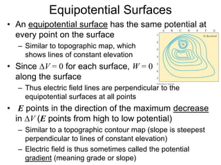
- 1. Equipotential Surfaces • An equipotential surface has the same potential at every point on the surface – Similar to topographic map, which shows lines of constant elevation • Since DV = 0 for each surface, W = 0 along the surface – Thus electric field lines are perpendicular to the equipotential surfaces at all points • E points in the direction of the maximum decrease in DV (E points from high to low potential) – Similar to a topographic contour map (slope is steepest perpendicular to lines of constant elevation) – Electric field is thus sometimes called the potential gradient (meaning grade or slope)
- 2. Equipotential Surfaces • On a contour map a hill is steepest where the lines of constant elevation are close together • If equipotential surfaces are drawn such that the potential difference between adjacent surfaces is constant, then the surfaces are closer together where the field is stronger
- 3. Examples of Equipotential Surfaces
- 4. Capacitance • A capacitor is a device that stores electrical potential energy by storing separated + and – charges – 2 conductors separated by vacuum, air, or insulation – + charge put on one conductor, equal amount of – charge put on the other conductor – A battery or power supply typically supplies the work necessary to separate the charge • Simplest form of capacitor is the parallel plate capacitor – 2 parallel plates, each with same area A, separated by distance d – Charge +Q on one plate, –Q on the other – If plates are close together, electric field will be uniform (constant) between the plates Charging A Capacitor
- 5. Capacitance • For a uniform electric field, the potential difference between the plates is (see Example Problem #16.6) DV = Ed – E is proportional to the charge, and DV is proportional to E therefore the charge is proportional to DV • The constant of proportionality between charge and DV is called capacitance – “Capacity” to hold charge for a given DV – 1 F is very large unit: typical values of C are mF, nF, or pF • Capacitance depends on the geometry of the plates and the material between the plates V Q C D Units: C / V = Farad (F) d A C 0 (for plates separated by air)
- 6. Capacitors in Circuits and Applications • Capacitors are used in a variety of electronic circuits – Example of “circuit diagram” consisting of capacitors and a battery shown at right • Many practical uses of capacitors – Some computer keyboard keys have capacitors with a variable plate spacing below them – Microphones using capacitors with one moving plate to create an electrical signal • Constant potential difference kept between plates by a battery • As plate spacing changes, charge flows onto and off of plates • The moving charge (current) is amplified to generate signal – Tweeters (speakers for high-frequency sounds) are microphones in reverse – Millions of microscopic capacitors used in each RAM computer memory chip • Charged and discharged capacitors correspond to 1 and 0 states
- 7. Combinations of Capacitors • Capacitors can be combined in circuits to give a particular net capacitance for the entire circuit • Parallel Combination – Potential difference across each capacitor is the same and equal to DV of the battery – Qtot = Q1 + Q2 + Q3 + … – Total (equivalent) capacitance: • Series Combination – Magnitude of charge is the same on all plates – DV (battery) = DV1 + DV2 + DV3 + … – Total (equivalent) capacitance: 3 2 1 eq C C C C 3 2 1 eq 1 1 1 1 C C C C
- 8. Example Problem Solution (details given in class): (a) 2.67 mF (b) 24.0 mC (each 8.00-mF capacitor), 18.0 mC (6.00-mF capacitor), 6.00 mC (2.00-mF capacitor) (c) 3.00 V (each capacitor) Find (a) the equivalent capacitance of the capacitors in the circuit shown, (b) the charge on each capacitor, and (c) the potential difference across each capacitor.
- 9. Energy Stored in a Charged Capacitor • It’s easy to tell that a capacitor stores (releases) energy when it charges (discharges) • The energy stored by the capacitor = work required to charge the capacitor (typically performed by a battery or power supply) • As more and more charge is transferred between the plates, the charge, voltage, and work done by battery increases (DW = DVDQ) • Total work done = total energy stored: • Defibrillators typically release about 1.2 kJ of stored energy from capacitor with DV ≈ 5 kV C Q V C V Q E 2 2 1 2 1 2 2 D D
- 10. Capacitors with Dielectrics • A dielectric is an insulating material – Rubber, plastic, glass, nylon • When a dielectric is inserted between the conductors of a capacitor, the capacitance increases • Capacitance increases for a parallel-plate capacitor in which a dielectric fills the entire space between the plates – k = dielectric constant (ratio of capacitance with dielectric to capacitance without dielectric) • For any given plate separation d, there is a maximum electric field (dielectric strength) that can be produced in the dielectric before it breaks down and conducts – See Table 16.1 for values of k and dielectric strength for various materials d A C 0 k
- 11. Capacitors with Dielectrics • The molecules of the dielectric, when placed in the electric field of a capacitor, become polarized – Centers of positive and negative charges become preferentially oriented in the field (see figure below at left) – Creates a net positive (negative) charge on the left (right) side of the dielectric (see figure below at right) – This helps attract more charge to the conducting plates for a given DV – Since plates can store more charge for a given voltage, the capacitance must increase (remember C = Q / DV )
- 12. Capacitors with Dielectrics • To increase capacitance while keeping the physical size reasonable, plates are often made of a thin conducting foil that is rolled into a cylinder – Dielectric material is sandwiched in between • High-voltage capacitor commonly consists of interwoven metal plates immersed in silicone oil • Very large capacitances can be achieved with an electrolytic capacitor at relatively low voltages – Insulating metal oxide layer forms on the conducting foil and serves as a (very thin) dielectric