SlideShare a Scribd company logo
1 of 256
Download to read offline
HiPAP hull units
High Precision Acoustic Positioning hull units
Instruction Manual
HiPAP hull units
High Precision Acoustic Positioning
hull units
Instruction Manual
857--160639
Note
Kongsberg Maritime AS makes every effort to ensure that the information contained
within this document is correct. However, our equipment is continuously being
improved and updated, so we cannot assume liability for any errors which may occur.
Warning
The equipment to which this manual applies must only be used for the purpose for
which it was designed. Improper use or maintenance may cause damage to the
equipment or injury to personnel. The user must be familiar with the contents of the
appropriate manuals before attempting to install, operate or maintain the equipment.
Kongsberg Maritime AS disclaims any responsibility for damage or injury caused by
improper installation, use or maintenance of the equipment.
Copyright
E 2003 Kongsberg Maritime AS
The information contained within this document remains the sole property of
Kongsberg Maritime AS. No part of this document may be copied or reproduced in any
form or by any means, and the information contained within is not to be communicated
to a third party, without the prior written consent of Kongsberg Maritime AS.
Contact information
Support: ui@kongsberg.com
Sales: subsea@kongsberg.com
Strandpromenaden 50
P.O.Box 111
N-3191 Horten,
Norway
Instruction Manual
I857-160639 / O
Sections
This book is the Instruction Manual for the HiPAP hull units system. It describes how to
operate, to install and to maintain the various units used by the HiPAP hull units
system.
1 Introduction
2 System description
3 Operation
4 Maintenance
5 Equipment handling
6 Installation
7 Technical specification
8 Cable layout and interconnections
9 Spare parts
10 HiPAP/HPR Test and alignment procedures
11 Drawing file
12 Index
HiPAP hull units
II 857-160639 / O
Remarks
References
Further information about the HiPAP system may be found in the following manuals:
• APOS HiPAP Instruction manual
• HiPAP Instruction manual
The reader
The maintenance information in this manual is intended to be used by a trained
maintenance technician or engineer, with experience of electronic and digital circuitry,
computers and electromechanical design. The level of information is based on
Kongsberg Maritime’s maintenance philosophy: The onboard technical personnel shall,
with the help of the documentation and the system’s built-in test functions, be able to
identify malfunctions, locate the fault, and replace major parts, modules and
components on the “Line Replaceable Unit” (LRU) level. He/she will however not
attempt to repair the LRUs.
The installation information in this manual is intended for the design and installation
engineers at the shipyard performing the installation. The information is supplied as the
basis for the shipyard’s own installation drawings applicable to the vessel. On
completion of the installation, this section may be used for reference purposes during
system maintenance.
Note
Distributed copies of this manual will not be updated. If your system software is
updated, you will be provided with copies of the latest revision of the manual.
Instruction Manual
III857-160639 / O
Contents
INTRODUCTION 1..............................................
Manual content 1. . . . . . . . . . . . . . . . . . . . . . . . . . . . . . . . . . . . . . . . . . . . . . . .
Abbreviations 1. . . . . . . . . . . . . . . . . . . . . . . . . . . . . . . . . . . . . . . . . . . . . . . . .
General guidelines 1. . . . . . . . . . . . . . . . . . . . . . . . . . . . . . . . . . . . . . . . . . . . .
Installation 1. . . . . . . . . . . . . . . . . . . . . . . . . . . . . . . . . . . . . . . . . . . . . .
Maintenance 2. . . . . . . . . . . . . . . . . . . . . . . . . . . . . . . . . . . . . . . . . . . .
Supply conditions 3. . . . . . . . . . . . . . . . . . . . . . . . . . . . . . . . . . . . . . . . . . . . . .
Equipment responsibility 3. . . . . . . . . . . . . . . . . . . . . . . . . . . . . . . . . .
Reception, unpacking and storage 3. . . . . . . . . . . . . . . . . . . . . . . . . . . .
Project management 3. . . . . . . . . . . . . . . . . . . . . . . . . . . . . . . . . . . . . .
Installation, supervision and commissioning 4. . . . . . . . . . . . . . . . . . .
Guarantee period 5. . . . . . . . . . . . . . . . . . . . . . . . . . . . . . . . . . . . . . . . .
SYSTEM DESCRIPTION 6......................................
Purpose 6. . . . . . . . . . . . . . . . . . . . . . . . . . . . . . . . . . . . . . . . . . . . . . . . . . . . . .
Overview 6. . . . . . . . . . . . . . . . . . . . . . . . . . . . . . . . . . . . . . . . . . . . . . . . . . . .
HiPAP 500 7. . . . . . . . . . . . . . . . . . . . . . . . . . . . . . . . . . . . . . . . . . . . . .
HiPAP 350 8. . . . . . . . . . . . . . . . . . . . . . . . . . . . . . . . . . . . . . . . . . . . . .
Hull unit system 9. . . . . . . . . . . . . . . . . . . . . . . . . . . . . . . . . . . . . . . . . . . . . . .
Hoist motor and gearbox 12. . . . . . . . . . . . . . . . . . . . . . . . . . . . . . . . . . . . . . . .
Gantry 12. . . . . . . . . . . . . . . . . . . . . . . . . . . . . . . . . . . . . . . . . . . . . . . . . . . . . . .
Shaft sleeve 12. . . . . . . . . . . . . . . . . . . . . . . . . . . . . . . . . . . . . . . . . . . . . . . . . . .
Transducer dock 13. . . . . . . . . . . . . . . . . . . . . . . . . . . . . . . . . . . . . . . . . . . . . . .
Mounting flange 13. . . . . . . . . . . . . . . . . . . . . . . . . . . . . . . . . . . . . . . . . . . . . . .
Transducer shaft 13. . . . . . . . . . . . . . . . . . . . . . . . . . . . . . . . . . . . . . . . . . . . . . .
Transducer 13. . . . . . . . . . . . . . . . . . . . . . . . . . . . . . . . . . . . . . . . . . . . . . . . . . .
Gate valve 14. . . . . . . . . . . . . . . . . . . . . . . . . . . . . . . . . . . . . . . . . . . . . . . . . . . .
Gate valve position indicator 14. . . . . . . . . . . . . . . . . . . . . . . . . . . . . . .
Hoist Control Unit 15. . . . . . . . . . . . . . . . . . . . . . . . . . . . . . . . . . . . . . . . . . . . .
Introduction 15. . . . . . . . . . . . . . . . . . . . . . . . . . . . . . . . . . . . . . . . . . . . .
External connections 15. . . . . . . . . . . . . . . . . . . . . . . . . . . . . . . . . . . . . .
Remote Control Unit 16. . . . . . . . . . . . . . . . . . . . . . . . . . . . . . . . . . . . . . . . . . .
General 16. . . . . . . . . . . . . . . . . . . . . . . . . . . . . . . . . . . . . . . . . . . . . . . .
External connections 16. . . . . . . . . . . . . . . . . . . . . . . . . . . . . . . . . . . . . .
Electrical system 17. . . . . . . . . . . . . . . . . . . . . . . . . . . . . . . . . . . . . . . . . . . . . . .
Introduction 17. . . . . . . . . . . . . . . . . . . . . . . . . . . . . . . . . . . . . . . . . . . . .
Circuit description 17. . . . . . . . . . . . . . . . . . . . . . . . . . . . . . . . . . . . . . . .
Electrical actuator (option) 28. . . . . . . . . . . . . . . . . . . . . . . . . . . . . . . . . . . . . . .
General 28. . . . . . . . . . . . . . . . . . . . . . . . . . . . . . . . . . . . . . . . . . . . . . . .
System 28. . . . . . . . . . . . . . . . . . . . . . . . . . . . . . . . . . . . . . . . . . . . . . . . .
Local control unit 29. . . . . . . . . . . . . . . . . . . . . . . . . . . . . . . . . . . . . . . .
Remote station 31. . . . . . . . . . . . . . . . . . . . . . . . . . . . . . . . . . . . . . . . . . .
Electrical connections 32. . . . . . . . . . . . . . . . . . . . . . . . . . . . . . . . . . . . .
HiPAP hull units
IV 857-160639 / O
OPERATION 33..................................................
Overview 33. . . . . . . . . . . . . . . . . . . . . . . . . . . . . . . . . . . . . . . . . . . . . . . . . . . .
Hoist control operation 34. . . . . . . . . . . . . . . . . . . . . . . . . . . . . . . . . . . . . . . . . .
General 34. . . . . . . . . . . . . . . . . . . . . . . . . . . . . . . . . . . . . . . . . . . . . . . .
Lowering the hull unit 35. . . . . . . . . . . . . . . . . . . . . . . . . . . . . . . . . . . . .
Raising the hull unit 35. . . . . . . . . . . . . . . . . . . . . . . . . . . . . . . . . . . . . .
Stopping the hull unit 35. . . . . . . . . . . . . . . . . . . . . . . . . . . . . . . . . . . . .
Remote operation of the hull unit 35. . . . . . . . . . . . . . . . . . . . . . . . . . . .
Remote control operation 36. . . . . . . . . . . . . . . . . . . . . . . . . . . . . . . . . . . . . . . .
Control buttons 37. . . . . . . . . . . . . . . . . . . . . . . . . . . . . . . . . . . . . . . . . .
Indicator lamps 37. . . . . . . . . . . . . . . . . . . . . . . . . . . . . . . . . . . . . . . . . .
Motor reset 37. . . . . . . . . . . . . . . . . . . . . . . . . . . . . . . . . . . . . . . . . . . . .
Manual operation of the hoist motor 38. . . . . . . . . . . . . . . . . . . . . . . . . . . . . . .
Procedure 38. . . . . . . . . . . . . . . . . . . . . . . . . . . . . . . . . . . . . . . . . . . . . . .
Gate valve operation 40. . . . . . . . . . . . . . . . . . . . . . . . . . . . . . . . . . . . . . . . . . . .
General 40. . . . . . . . . . . . . . . . . . . . . . . . . . . . . . . . . . . . . . . . . . . . . . . .
Manual operation 40. . . . . . . . . . . . . . . . . . . . . . . . . . . . . . . . . . . . . . . .
Using the actuator remote control unit 41. . . . . . . . . . . . . . . . . . . . . . . .
MAINTENANCE 42...............................................
Overview 42. . . . . . . . . . . . . . . . . . . . . . . . . . . . . . . . . . . . . . . . . . . . . . . . . . . .
Safety 42. . . . . . . . . . . . . . . . . . . . . . . . . . . . . . . . . . . . . . . . . . . . . . . . . . . . . . .
Watertightness test 42. . . . . . . . . . . . . . . . . . . . . . . . . . . . . . . . . . . . . . . . . . . . .
Torques 43. . . . . . . . . . . . . . . . . . . . . . . . . . . . . . . . . . . . . . . . . . . . . . . . . . . . . .
Tools 44. . . . . . . . . . . . . . . . . . . . . . . . . . . . . . . . . . . . . . . . . . . . . . . . . . . . . . . .
Standard tools 44. . . . . . . . . . . . . . . . . . . . . . . . . . . . . . . . . . . . . . . . . . .
Special tools 44. . . . . . . . . . . . . . . . . . . . . . . . . . . . . . . . . . . . . . . . . . . .
Before you start 45. . . . . . . . . . . . . . . . . . . . . . . . . . . . . . . . . . . . . . . . . . . . . . .
Preventive maintenance schedule 45. . . . . . . . . . . . . . . . . . . . . . . . . . . . . . . . . .
General 45. . . . . . . . . . . . . . . . . . . . . . . . . . . . . . . . . . . . . . . . . . . . . . . .
Maintenance chart 45. . . . . . . . . . . . . . . . . . . . . . . . . . . . . . . . . . . . . . . .
Lubrication 45. . . . . . . . . . . . . . . . . . . . . . . . . . . . . . . . . . . . . . . . . . . . .
Special attention 46. . . . . . . . . . . . . . . . . . . . . . . . . . . . . . . . . . . . . . . . .
Hull unit general inspection 47. . . . . . . . . . . . . . . . . . . . . . . . . . . . . . . . . . . . . .
General 47. . . . . . . . . . . . . . . . . . . . . . . . . . . . . . . . . . . . . . . . . . . . . . . .
Logistics 47. . . . . . . . . . . . . . . . . . . . . . . . . . . . . . . . . . . . . . . . . . . . . . .
Procedure 47. . . . . . . . . . . . . . . . . . . . . . . . . . . . . . . . . . . . . . . . . . . . . . .
Hoist Control Unit 49. . . . . . . . . . . . . . . . . . . . . . . . . . . . . . . . . . . . . . . . . . . . .
Internal layout 49. . . . . . . . . . . . . . . . . . . . . . . . . . . . . . . . . . . . . . . . . . .
Hoist Control Unit inspection 50. . . . . . . . . . . . . . . . . . . . . . . . . . . . . . .
Remote Control Unit 52. . . . . . . . . . . . . . . . . . . . . . . . . . . . . . . . . . . . . . . . . . .
Internal layout 52. . . . . . . . . . . . . . . . . . . . . . . . . . . . . . . . . . . . . . . . . . .
Remote Control Unit inspection 53. . . . . . . . . . . . . . . . . . . . . . . . . . . . .
Watertightness test 55. . . . . . . . . . . . . . . . . . . . . . . . . . . . . . . . . . . . . . . . . . . . .
Logistics 55. . . . . . . . . . . . . . . . . . . . . . . . . . . . . . . . . . . . . . . . . . . . . . .
Procedure 55. . . . . . . . . . . . . . . . . . . . . . . . . . . . . . . . . . . . . . . . . . . . . . .
Instruction Manual
V857-160639 / O
Corrective maintenance 56. . . . . . . . . . . . . . . . . . . . . . . . . . . . . . . . . . . . . . . . .
Overview 56. . . . . . . . . . . . . . . . . . . . . . . . . . . . . . . . . . . . . . . . . . . . . . .
General 56. . . . . . . . . . . . . . . . . . . . . . . . . . . . . . . . . . . . . . . . . . . . . . . .
Hoist motor, gear box lubrication 57. . . . . . . . . . . . . . . . . . . . . . . . . . . . . . . . . .
Logistics 57. . . . . . . . . . . . . . . . . . . . . . . . . . . . . . . . . . . . . . . . . . . . . . .
Procedure 57. . . . . . . . . . . . . . . . . . . . . . . . . . . . . . . . . . . . . . . . . . . . . . .
Hoist motor, replacement 58. . . . . . . . . . . . . . . . . . . . . . . . . . . . . . . . . . . . . . . .
Logistics 58. . . . . . . . . . . . . . . . . . . . . . . . . . . . . . . . . . . . . . . . . . . . . . .
Procedure 58. . . . . . . . . . . . . . . . . . . . . . . . . . . . . . . . . . . . . . . . . . . . . . .
Hoist motor, gear box replacement 59. . . . . . . . . . . . . . . . . . . . . . . . . . . . . . . .
Logistics 59. . . . . . . . . . . . . . . . . . . . . . . . . . . . . . . . . . . . . . . . . . . . . . .
Procedure 59. . . . . . . . . . . . . . . . . . . . . . . . . . . . . . . . . . . . . . . . . . . . . . .
Drive chains, lubrication 61. . . . . . . . . . . . . . . . . . . . . . . . . . . . . . . . . . . . . . . .
Logistics 61. . . . . . . . . . . . . . . . . . . . . . . . . . . . . . . . . . . . . . . . . . . . . . .
Procedure 61. . . . . . . . . . . . . . . . . . . . . . . . . . . . . . . . . . . . . . . . . . . . . . .
Drive chains, tension 61. . . . . . . . . . . . . . . . . . . . . . . . . . . . . . . . . . . . . . . . . . .
Logistics 61. . . . . . . . . . . . . . . . . . . . . . . . . . . . . . . . . . . . . . . . . . . . . . .
Test procedure 62. . . . . . . . . . . . . . . . . . . . . . . . . . . . . . . . . . . . . . . . . . .
Adjusting the tension 63. . . . . . . . . . . . . . . . . . . . . . . . . . . . . . . . . . . . .
Drive chains, replacement 63. . . . . . . . . . . . . . . . . . . . . . . . . . . . . . . . . . . . . . .
Logistics 63. . . . . . . . . . . . . . . . . . . . . . . . . . . . . . . . . . . . . . . . . . . . . . .
Procedure 63. . . . . . . . . . . . . . . . . . . . . . . . . . . . . . . . . . . . . . . . . . . . . . .
Opening the service dock 64. . . . . . . . . . . . . . . . . . . . . . . . . . . . . . . . . . . . . . . .
Logistics 64. . . . . . . . . . . . . . . . . . . . . . . . . . . . . . . . . . . . . . . . . . . . . . .
Procedure 64. . . . . . . . . . . . . . . . . . . . . . . . . . . . . . . . . . . . . . . . . . . . . . .
Lifting the hull unit 65. . . . . . . . . . . . . . . . . . . . . . . . . . . . . . . . . . . . . . . . . . . .
Logistics 65. . . . . . . . . . . . . . . . . . . . . . . . . . . . . . . . . . . . . . . . . . . . . . .
Procedure 65. . . . . . . . . . . . . . . . . . . . . . . . . . . . . . . . . . . . . . . . . . . . . . .
Transducer, replacement 67. . . . . . . . . . . . . . . . . . . . . . . . . . . . . . . . . . . . . . . . .
Logistics 67. . . . . . . . . . . . . . . . . . . . . . . . . . . . . . . . . . . . . . . . . . . . . . .
Procedure 67. . . . . . . . . . . . . . . . . . . . . . . . . . . . . . . . . . . . . . . . . . . . . . .
Transducer, marine growth removal 69. . . . . . . . . . . . . . . . . . . . . . . . . . . . . . . .
Logistics 69. . . . . . . . . . . . . . . . . . . . . . . . . . . . . . . . . . . . . . . . . . . . . . .
Procedure 69. . . . . . . . . . . . . . . . . . . . . . . . . . . . . . . . . . . . . . . . . . . . . . .
HiPAP 500 transducer cable, replacement 70. . . . . . . . . . . . . . . . . . . . . . . . . . .
Logistics 70. . . . . . . . . . . . . . . . . . . . . . . . . . . . . . . . . . . . . . . . . . . . . . .
Procedure 70. . . . . . . . . . . . . . . . . . . . . . . . . . . . . . . . . . . . . . . . . . . . . . .
HiPAP 350 transducer cables, replacement 73. . . . . . . . . . . . . . . . . . . . . . . . . .
Logistics 73. . . . . . . . . . . . . . . . . . . . . . . . . . . . . . . . . . . . . . . . . . . . . . .
Cable 1 73. . . . . . . . . . . . . . . . . . . . . . . . . . . . . . . . . . . . . . . . . . . . . . . .
Cable 2 76. . . . . . . . . . . . . . . . . . . . . . . . . . . . . . . . . . . . . . . . . . . . . . . .
Shaft sleeve, lubrication 77. . . . . . . . . . . . . . . . . . . . . . . . . . . . . . . . . . . . . . . . .
Logistics 77. . . . . . . . . . . . . . . . . . . . . . . . . . . . . . . . . . . . . . . . . . . . . . .
Procedure 77. . . . . . . . . . . . . . . . . . . . . . . . . . . . . . . . . . . . . . . . . . . . . . .
HiPAP hull units
VI 857-160639 / O
Shaft sleeve, disassembly 78. . . . . . . . . . . . . . . . . . . . . . . . . . . . . . . . . . . . . . . .
Logistics 78. . . . . . . . . . . . . . . . . . . . . . . . . . . . . . . . . . . . . . . . . . . . . . .
Procedure 78. . . . . . . . . . . . . . . . . . . . . . . . . . . . . . . . . . . . . . . . . . . . . . .
Zinc anode, inspection and replacement 81. . . . . . . . . . . . . . . . . . . . . . . . . . . .
Logistics 81. . . . . . . . . . . . . . . . . . . . . . . . . . . . . . . . . . . . . . . . . . . . . . .
Procedure 81. . . . . . . . . . . . . . . . . . . . . . . . . . . . . . . . . . . . . . . . . . . . . . .
Transducer shaft, guide rails adjustment 82. . . . . . . . . . . . . . . . . . . . . . . . . . . .
Logistics 82. . . . . . . . . . . . . . . . . . . . . . . . . . . . . . . . . . . . . . . . . . . . . . .
Procedure 82. . . . . . . . . . . . . . . . . . . . . . . . . . . . . . . . . . . . . . . . . . . . . . .
Limit switches, replacement 83. . . . . . . . . . . . . . . . . . . . . . . . . . . . . . . . . . . . . .
Logistics 83. . . . . . . . . . . . . . . . . . . . . . . . . . . . . . . . . . . . . . . . . . . . . . .
Procedure 83. . . . . . . . . . . . . . . . . . . . . . . . . . . . . . . . . . . . . . . . . . . . . . .
Gate valve, replacement 84. . . . . . . . . . . . . . . . . . . . . . . . . . . . . . . . . . . . . . . . .
General 84. . . . . . . . . . . . . . . . . . . . . . . . . . . . . . . . . . . . . . . . . . . . . . . .
Logistics 84. . . . . . . . . . . . . . . . . . . . . . . . . . . . . . . . . . . . . . . . . . . . . . .
Procedure 84. . . . . . . . . . . . . . . . . . . . . . . . . . . . . . . . . . . . . . . . . . . . . . .
Gate valve position indicator, replacement 86. . . . . . . . . . . . . . . . . . . . .
Position indicator switch unit, replacement 87. . . . . . . . . . . . . . . . . . . .
Hoist Control Unit 88. . . . . . . . . . . . . . . . . . . . . . . . . . . . . . . . . . . . . . . . . . . . .
General 88. . . . . . . . . . . . . . . . . . . . . . . . . . . . . . . . . . . . . . . . . . . . . . . .
Logistics 88. . . . . . . . . . . . . . . . . . . . . . . . . . . . . . . . . . . . . . . . . . . . . . .
References 88. . . . . . . . . . . . . . . . . . . . . . . . . . . . . . . . . . . . . . . . . . . . . .
Replacement of Hoist Control Unit parts 89. . . . . . . . . . . . . . . . . . . . . .
Remote Control Unit 90. . . . . . . . . . . . . . . . . . . . . . . . . . . . . . . . . . . . . . . . . . .
General 90. . . . . . . . . . . . . . . . . . . . . . . . . . . . . . . . . . . . . . . . . . . . . . . .
Logistics 90. . . . . . . . . . . . . . . . . . . . . . . . . . . . . . . . . . . . . . . . . . . . . . .
References 90. . . . . . . . . . . . . . . . . . . . . . . . . . . . . . . . . . . . . . . . . . . . . .
Replacement of Remote Control Unit parts 91. . . . . . . . . . . . . . . . . . . .
Electrical actuator (option) 93. . . . . . . . . . . . . . . . . . . . . . . . . . . . . . . . . . . . . . .
Logistics 93. . . . . . . . . . . . . . . . . . . . . . . . . . . . . . . . . . . . . . . . . . . . . . .
References 93. . . . . . . . . . . . . . . . . . . . . . . . . . . . . . . . . . . . . . . . . . . . . .
Inspection 93. . . . . . . . . . . . . . . . . . . . . . . . . . . . . . . . . . . . . . . . . . . . . .
Lubrication 93. . . . . . . . . . . . . . . . . . . . . . . . . . . . . . . . . . . . . . . . . . . . .
Electrical connections 93. . . . . . . . . . . . . . . . . . . . . . . . . . . . . . . . . . . . .
Actuator local control unit, inspection 94. . . . . . . . . . . . . . . . . . . . . . . .
Actuator remote station, inspection 95. . . . . . . . . . . . . . . . . . . . . . . . . .
Replacement of remote station and local control unit parts 96. . . . . . . .
Test procedure 99. . . . . . . . . . . . . . . . . . . . . . . . . . . . . . . . . . . . . . . . . . . . . . . .
General checks 99. . . . . . . . . . . . . . . . . . . . . . . . . . . . . . . . . . . . . . . . . .
System alignment 99. . . . . . . . . . . . . . . . . . . . . . . . . . . . . . . . . . . . . . . .
Instruction Manual
VII857-160639 / O
EQUIPMENT HANDLING 100.....................................
Introduction 100. . . . . . . . . . . . . . . . . . . . . . . . . . . . . . . . . . . . . . . . . . . . . . . . . .
Transportation 100. . . . . . . . . . . . . . . . . . . . . . . . . . . . . . . . . . . . . . . . . . . . . . . . .
General specifications 100. . . . . . . . . . . . . . . . . . . . . . . . . . . . . . . . . . . . .
Local transportation 100. . . . . . . . . . . . . . . . . . . . . . . . . . . . . . . . . . . . . .
Initial preservation 101. . . . . . . . . . . . . . . . . . . . . . . . . . . . . . . . . . . . . . . . . . . . .
Inspection and unpacking 103. . . . . . . . . . . . . . . . . . . . . . . . . . . . . . . . . . . . . . . .
Storage 105. . . . . . . . . . . . . . . . . . . . . . . . . . . . . . . . . . . . . . . . . . . . . . . . . . . . . .
After use storage 106. . . . . . . . . . . . . . . . . . . . . . . . . . . . . . . . . . . . . . . . .
Re-packing 108. . . . . . . . . . . . . . . . . . . . . . . . . . . . . . . . . . . . . . . . . . . . .
ESD precautions 108. . . . . . . . . . . . . . . . . . . . . . . . . . . . . . . . . . . . . . . . . . . . . . .
Temperature protection 109. . . . . . . . . . . . . . . . . . . . . . . . . . . . . . . . . . . . . . . . . .
INSTALLATION 110...............................................
Overview 110. . . . . . . . . . . . . . . . . . . . . . . . . . . . . . . . . . . . . . . . . . . . . . . . . . . .
Configuration 110. . . . . . . . . . . . . . . . . . . . . . . . . . . . . . . . . . . . . . . . . . . . . . . . .
Installation procedures overview 111. . . . . . . . . . . . . . . . . . . . . . . . . . . . . . . . . .
Installation requirements 112. . . . . . . . . . . . . . . . . . . . . . . . . . . . . . . . . . . . . . . .
Supply power 112. . . . . . . . . . . . . . . . . . . . . . . . . . . . . . . . . . . . . . . . . . .
Environmental requirements 112. . . . . . . . . . . . . . . . . . . . . . . . . . . . . . . .
Sonar room requirements 113. . . . . . . . . . . . . . . . . . . . . . . . . . . . . . . . . . . . . . . .
General 113. . . . . . . . . . . . . . . . . . . . . . . . . . . . . . . . . . . . . . . . . . . . . . . .
Ventilation 113. . . . . . . . . . . . . . . . . . . . . . . . . . . . . . . . . . . . . . . . . . . . . .
Bilge pump system 113. . . . . . . . . . . . . . . . . . . . . . . . . . . . . . . . . . . . . . .
Precautions and requirements 114. . . . . . . . . . . . . . . . . . . . . . . . . . . . . . . . . . . . .
General installation information 115. . . . . . . . . . . . . . . . . . . . . . . . . . . . . . . . . . .
Introduction 115. . . . . . . . . . . . . . . . . . . . . . . . . . . . . . . . . . . . . . . . . . . . .
References 115. . . . . . . . . . . . . . . . . . . . . . . . . . . . . . . . . . . . . . . . . . . . . .
Logistics 115. . . . . . . . . . . . . . . . . . . . . . . . . . . . . . . . . . . . . . . . . . . . . . .
Choice of location 115. . . . . . . . . . . . . . . . . . . . . . . . . . . . . . . . . . . . . . . .
Additional points 116. . . . . . . . . . . . . . . . . . . . . . . . . . . . . . . . . . . . . . . . .
Installation of the mounting flange 118. . . . . . . . . . . . . . . . . . . . . . . . . . . . . . . .
General 118. . . . . . . . . . . . . . . . . . . . . . . . . . . . . . . . . . . . . . . . . . . . . . . .
DN500 mounting flange 118. . . . . . . . . . . . . . . . . . . . . . . . . . . . . . . . . . .
DN350 mounting flange 118. . . . . . . . . . . . . . . . . . . . . . . . . . . . . . . . . . .
Installation accuracy and tolerances 119. . . . . . . . . . . . . . . . . . . . . . . . . .
Logistics 119. . . . . . . . . . . . . . . . . . . . . . . . . . . . . . . . . . . . . . . . . . . . . . .
References 119. . . . . . . . . . . . . . . . . . . . . . . . . . . . . . . . . . . . . . . . . . . . . .
Installation procedure 120. . . . . . . . . . . . . . . . . . . . . . . . . . . . . . . . . . . . .
HiPAP hull units
VIII 857-160639 / O
Installation of a gate valve 121. . . . . . . . . . . . . . . . . . . . . . . . . . . . . . . . . . . . . . .
Introduction 121. . . . . . . . . . . . . . . . . . . . . . . . . . . . . . . . . . . . . . . . . . . . .
Location of the unit 121. . . . . . . . . . . . . . . . . . . . . . . . . . . . . . . . . . . . . . .
Logistics 121. . . . . . . . . . . . . . . . . . . . . . . . . . . . . . . . . . . . . . . . . . . . . . .
References 121. . . . . . . . . . . . . . . . . . . . . . . . . . . . . . . . . . . . . . . . . . . . . .
O-ring and flange gasket 121. . . . . . . . . . . . . . . . . . . . . . . . . . . . . . . . . . .
Procedure 122. . . . . . . . . . . . . . . . . . . . . . . . . . . . . . . . . . . . . . . . . . . . . . .
Installation of the gantry 123. . . . . . . . . . . . . . . . . . . . . . . . . . . . . . . . . . . . . . . .
General 123. . . . . . . . . . . . . . . . . . . . . . . . . . . . . . . . . . . . . . . . . . . . . . . .
References 123. . . . . . . . . . . . . . . . . . . . . . . . . . . . . . . . . . . . . . . . . . . . . .
Logistics 123. . . . . . . . . . . . . . . . . . . . . . . . . . . . . . . . . . . . . . . . . . . . . . .
Procedure 123. . . . . . . . . . . . . . . . . . . . . . . . . . . . . . . . . . . . . . . . . . . . . . .
Mounting the hoist motor 125. . . . . . . . . . . . . . . . . . . . . . . . . . . . . . . . . . . . . . . .
Introduction 125. . . . . . . . . . . . . . . . . . . . . . . . . . . . . . . . . . . . . . . . . . . . .
Procedure 125. . . . . . . . . . . . . . . . . . . . . . . . . . . . . . . . . . . . . . . . . . . . . . .
Hull unit surface protection 126. . . . . . . . . . . . . . . . . . . . . . . . . . . . . . . . . . . . . .
General 126. . . . . . . . . . . . . . . . . . . . . . . . . . . . . . . . . . . . . . . . . . . . . . . .
Logistics 126. . . . . . . . . . . . . . . . . . . . . . . . . . . . . . . . . . . . . . . . . . . . . . .
Installation of the Hoist Control Unit 127. . . . . . . . . . . . . . . . . . . . . . . . . . . . . . .
Introduction 127. . . . . . . . . . . . . . . . . . . . . . . . . . . . . . . . . . . . . . . . . . . . .
Unit location 127. . . . . . . . . . . . . . . . . . . . . . . . . . . . . . . . . . . . . . . . . . . .
Logistics 127. . . . . . . . . . . . . . . . . . . . . . . . . . . . . . . . . . . . . . . . . . . . . . .
References 127. . . . . . . . . . . . . . . . . . . . . . . . . . . . . . . . . . . . . . . . . . . . . .
Procedure 128. . . . . . . . . . . . . . . . . . . . . . . . . . . . . . . . . . . . . . . . . . . . . . .
Installation of the Remote Control Unit 129. . . . . . . . . . . . . . . . . . . . . . . . . . . . .
General 129. . . . . . . . . . . . . . . . . . . . . . . . . . . . . . . . . . . . . . . . . . . . . . . .
Location of the unit 129. . . . . . . . . . . . . . . . . . . . . . . . . . . . . . . . . . . . . . .
Logistics 129. . . . . . . . . . . . . . . . . . . . . . . . . . . . . . . . . . . . . . . . . . . . . . .
References 129. . . . . . . . . . . . . . . . . . . . . . . . . . . . . . . . . . . . . . . . . . . . . .
Installation procedure 129. . . . . . . . . . . . . . . . . . . . . . . . . . . . . . . . . . . . .
Pin allocations 130. . . . . . . . . . . . . . . . . . . . . . . . . . . . . . . . . . . . . . . . . . .
Electrical actuator (option) 131. . . . . . . . . . . . . . . . . . . . . . . . . . . . . . . . . . . . . . .
General 131. . . . . . . . . . . . . . . . . . . . . . . . . . . . . . . . . . . . . . . . . . . . . . . .
Location of the unit 131. . . . . . . . . . . . . . . . . . . . . . . . . . . . . . . . . . . . . . .
Logistics 131. . . . . . . . . . . . . . . . . . . . . . . . . . . . . . . . . . . . . . . . . . . . . . .
References 131. . . . . . . . . . . . . . . . . . . . . . . . . . . . . . . . . . . . . . . . . . . . . .
Mounting procedure 131. . . . . . . . . . . . . . . . . . . . . . . . . . . . . . . . . . . . . .
Switch settings 132. . . . . . . . . . . . . . . . . . . . . . . . . . . . . . . . . . . . . . . . . .
Wiring diagrams 133. . . . . . . . . . . . . . . . . . . . . . . . . . . . . . . . . . . . . . . . .
Installation of the remote station 134. . . . . . . . . . . . . . . . . . . . . . . . . . . . .
Installation of the local control unit 135. . . . . . . . . . . . . . . . . . . . . . . . . . . . . . . .
General 135. . . . . . . . . . . . . . . . . . . . . . . . . . . . . . . . . . . . . . . . . . . . . . . .
Location of the unit 135. . . . . . . . . . . . . . . . . . . . . . . . . . . . . . . . . . . . . . .
Logistics 135. . . . . . . . . . . . . . . . . . . . . . . . . . . . . . . . . . . . . . . . . . . . . . .
References 135. . . . . . . . . . . . . . . . . . . . . . . . . . . . . . . . . . . . . . . . . . . . . .
Procedure 135. . . . . . . . . . . . . . . . . . . . . . . . . . . . . . . . . . . . . . . . . . . . . . .
Instruction Manual
IX857-160639 / O
TECHNICAL SPECIFICATION 137................................
Overview 137. . . . . . . . . . . . . . . . . . . . . . . . . . . . . . . . . . . . . . . . . . . . . . . . . . . .
Packed dimensions and weights 138. . . . . . . . . . . . . . . . . . . . . . . . . . . . . . . . . . .
HiPAP 500 gantry with dock 138. . . . . . . . . . . . . . . . . . . . . . . . . . . . . . .
HiPAP 350 gantry with dock 138. . . . . . . . . . . . . . . . . . . . . . . . . . . . . . .
Hull units outline dimensions 139. . . . . . . . . . . . . . . . . . . . . . . . . . . . . . . . . . . . .
HiPAP 500 139. . . . . . . . . . . . . . . . . . . . . . . . . . . . . . . . . . . . . . . . . . . . . .
HiPAP 350 139. . . . . . . . . . . . . . . . . . . . . . . . . . . . . . . . . . . . . . . . . . . . . .
500 mm mounting flange 140. . . . . . . . . . . . . . . . . . . . . . . . . . . . . . . . . .
500 mm gate valve 140. . . . . . . . . . . . . . . . . . . . . . . . . . . . . . . . . . . . . . .
350 mm mounting flange 141. . . . . . . . . . . . . . . . . . . . . . . . . . . . . . . . . .
350 mm gate valve 141. . . . . . . . . . . . . . . . . . . . . . . . . . . . . . . . . . . . . . .
Gantry 142. . . . . . . . . . . . . . . . . . . . . . . . . . . . . . . . . . . . . . . . . . . . . . . . .
Lubrication 143. . . . . . . . . . . . . . . . . . . . . . . . . . . . . . . . . . . . . . . . . . . . . . . . . . .
Equivalents 143. . . . . . . . . . . . . . . . . . . . . . . . . . . . . . . . . . . . . . . . . . . . .
Hoist Control Unit 144. . . . . . . . . . . . . . . . . . . . . . . . . . . . . . . . . . . . . . . . . . . . .
General 144. . . . . . . . . . . . . . . . . . . . . . . . . . . . . . . . . . . . . . . . . . . . . . . .
Unit dimensions 144. . . . . . . . . . . . . . . . . . . . . . . . . . . . . . . . . . . . . . . . .
Power supply 144. . . . . . . . . . . . . . . . . . . . . . . . . . . . . . . . . . . . . . . . . . . .
Environment 144. . . . . . . . . . . . . . . . . . . . . . . . . . . . . . . . . . . . . . . . . . . .
Remote Control Unit 147. . . . . . . . . . . . . . . . . . . . . . . . . . . . . . . . . . . . . . . . . . .
Unit dimensions 147. . . . . . . . . . . . . . . . . . . . . . . . . . . . . . . . . . . . . . . . .
Power supply 147. . . . . . . . . . . . . . . . . . . . . . . . . . . . . . . . . . . . . . . . . . . .
Environment 147. . . . . . . . . . . . . . . . . . . . . . . . . . . . . . . . . . . . . . . . . . . .
Cabling 147. . . . . . . . . . . . . . . . . . . . . . . . . . . . . . . . . . . . . . . . . . . . . . . .
Raise and lower motor 149. . . . . . . . . . . . . . . . . . . . . . . . . . . . . . . . . . . . . . . . . .
Transducers 150. . . . . . . . . . . . . . . . . . . . . . . . . . . . . . . . . . . . . . . . . . . . . . . . . . .
HiPAP 500 150. . . . . . . . . . . . . . . . . . . . . . . . . . . . . . . . . . . . . . . . . . . . . .
HiPAP 350 150. . . . . . . . . . . . . . . . . . . . . . . . . . . . . . . . . . . . . . . . . . . . . .
Actuator (option) 151. . . . . . . . . . . . . . . . . . . . . . . . . . . . . . . . . . . . . . . . . . . . . .
General 151. . . . . . . . . . . . . . . . . . . . . . . . . . . . . . . . . . . . . . . . . . . . . . . .
Unit dimensions 151. . . . . . . . . . . . . . . . . . . . . . . . . . . . . . . . . . . . . . . . .
Electrical motor 151. . . . . . . . . . . . . . . . . . . . . . . . . . . . . . . . . . . . . . . . . .
Remote station 151. . . . . . . . . . . . . . . . . . . . . . . . . . . . . . . . . . . . . . . . . . .
Local control unit 151. . . . . . . . . . . . . . . . . . . . . . . . . . . . . . . . . . . . . . . .
Environment temperature 151. . . . . . . . . . . . . . . . . . . . . . . . . . . . . . . . . .
HiPAP hull units
X 857-160639 / O
CABLE LAYOUT AND INTERCONNECTIONS 152.................
Overview 152. . . . . . . . . . . . . . . . . . . . . . . . . . . . . . . . . . . . . . . . . . . . . . . . . . . .
Cable gland assembly procedure 153. . . . . . . . . . . . . . . . . . . . . . . . . . . . . . . . . .
Purpose 153. . . . . . . . . . . . . . . . . . . . . . . . . . . . . . . . . . . . . . . . . . . . . . . .
General procedure 153. . . . . . . . . . . . . . . . . . . . . . . . . . . . . . . . . . . . . . . .
Securing and terminating the cables 154. . . . . . . . . . . . . . . . . . . . . . . . . .
Multi-diameter modules 154. . . . . . . . . . . . . . . . . . . . . . . . . . . . . . . . . . .
Standard type 157. . . . . . . . . . . . . . . . . . . . . . . . . . . . . . . . . . . . . . . . . . . .
Additional type 1 (842-093878) 159. . . . . . . . . . . . . . . . . . . . . . . . . . . . .
Additional type 2 (541-093642) 159. . . . . . . . . . . . . . . . . . . . . . . . . . . . .
Basic cabling requirements 161. . . . . . . . . . . . . . . . . . . . . . . . . . . . . . . . . . . . . . .
HiPAP cable plan 164. . . . . . . . . . . . . . . . . . . . . . . . . . . . . . . . . . . . . . . . . . . . . .
Cable specifications 165. . . . . . . . . . . . . . . . . . . . . . . . . . . . . . . . . . . . . . . . . . . .
Shipyard cables 165. . . . . . . . . . . . . . . . . . . . . . . . . . . . . . . . . . . . . . . . . .
System cables 165. . . . . . . . . . . . . . . . . . . . . . . . . . . . . . . . . . . . . . . . . . .
Cable connections 165. . . . . . . . . . . . . . . . . . . . . . . . . . . . . . . . . . . . . . . . . . . . . .
Special cables 165. . . . . . . . . . . . . . . . . . . . . . . . . . . . . . . . . . . . . . . . . . . . . . . . .
Hull unit cables 166. . . . . . . . . . . . . . . . . . . . . . . . . . . . . . . . . . . . . . . . . . . . . . . .
HiPAP 500 system 166. . . . . . . . . . . . . . . . . . . . . . . . . . . . . . . . . . . . . . .
HiPAP 350 system 167. . . . . . . . . . . . . . . . . . . . . . . . . . . . . . . . . . . . . . .
Cables interconnection 170. . . . . . . . . . . . . . . . . . . . . . . . . . . . . . . . . . . . . . . . . .
Cable K 170. . . . . . . . . . . . . . . . . . . . . . . . . . . . . . . . . . . . . . . . . . . . . . . .
Cable M 173. . . . . . . . . . . . . . . . . . . . . . . . . . . . . . . . . . . . . . . . . . . . . . . .
Cable N 173. . . . . . . . . . . . . . . . . . . . . . . . . . . . . . . . . . . . . . . . . . . . . . . .
Cable O 173. . . . . . . . . . . . . . . . . . . . . . . . . . . . . . . . . . . . . . . . . . . . . . . .
Cable P 173. . . . . . . . . . . . . . . . . . . . . . . . . . . . . . . . . . . . . . . . . . . . . . . .
Cable Q 173. . . . . . . . . . . . . . . . . . . . . . . . . . . . . . . . . . . . . . . . . . . . . . . .
Cable Y 174. . . . . . . . . . . . . . . . . . . . . . . . . . . . . . . . . . . . . . . . . . . . . . . .
Cable installation 176. . . . . . . . . . . . . . . . . . . . . . . . . . . . . . . . . . . . . . . . . . . . . .
Logistics 176. . . . . . . . . . . . . . . . . . . . . . . . . . . . . . . . . . . . . . . . . . . . . . .
References 176. . . . . . . . . . . . . . . . . . . . . . . . . . . . . . . . . . . . . . . . . . . . . .
Installation procedure 176. . . . . . . . . . . . . . . . . . . . . . . . . . . . . . . . . . . . .
Actuator connections (option) 177. . . . . . . . . . . . . . . . . . . . . . . . . . . . . . . . . . . .
Cables 177. . . . . . . . . . . . . . . . . . . . . . . . . . . . . . . . . . . . . . . . . . . . . . . . .
SPARE PARTS 178.................................................
Codes used 178. . . . . . . . . . . . . . . . . . . . . . . . . . . . . . . . . . . . . . . . . . . . . . . . . . .
Consumables and repair kits 179. . . . . . . . . . . . . . . . . . . . . . . . . . . . . . . . . . . . . .
Main units spare parts list 180. . . . . . . . . . . . . . . . . . . . . . . . . . . . . . . . . . . . . . . .
Hull Unit assembly spare parts list 181. . . . . . . . . . . . . . . . . . . . . . . . . . . . . . . . .
Chains 182. . . . . . . . . . . . . . . . . . . . . . . . . . . . . . . . . . . . . . . . . . . . . . . . . . . . . . .
Chains spare parts list 183. . . . . . . . . . . . . . . . . . . . . . . . . . . . . . . . . . . . .
Dock 184. . . . . . . . . . . . . . . . . . . . . . . . . . . . . . . . . . . . . . . . . . . . . . . . . . . . . . . .
Dock spare parts list 185. . . . . . . . . . . . . . . . . . . . . . . . . . . . . . . . . . . . . .
Transducer shaft sleeve 186. . . . . . . . . . . . . . . . . . . . . . . . . . . . . . . . . . . . . . . . .
Transducer shaft sleeve spare parts list 187. . . . . . . . . . . . . . . . . . . . . . . .
Instruction Manual
XI857-160639 / O
Transducer shaft sleeve-top 188. . . . . . . . . . . . . . . . . . . . . . . . . . . . . . . . . . . . . .
Transducer 189. . . . . . . . . . . . . . . . . . . . . . . . . . . . . . . . . . . . . . . . . . . . . . . . . . .
Standard transducer spare parts list 189. . . . . . . . . . . . . . . . . . . . . . . . . . .
Remote Control Unit 190. . . . . . . . . . . . . . . . . . . . . . . . . . . . . . . . . . . . . . . . . . .
Remote Control Unit spare parts list 190. . . . . . . . . . . . . . . . . . . . . . . . . .
Hoist Control Unit 191. . . . . . . . . . . . . . . . . . . . . . . . . . . . . . . . . . . . . . . . . . . . .
Hoist Control Unit spare parts 191. . . . . . . . . . . . . . . . . . . . . . . . . . . . . .
TEST AND ALIGNMENT PROCEDURES 192.......................
Introduction 193. . . . . . . . . . . . . . . . . . . . . . . . . . . . . . . . . . . . . . . . . . . . . . . . . .
Purpose 193. . . . . . . . . . . . . . . . . . . . . . . . . . . . . . . . . . . . . . . . . . . . . . . .
Test certificates 193. . . . . . . . . . . . . . . . . . . . . . . . . . . . . . . . . . . . . . . . . .
Visual inspections 193. . . . . . . . . . . . . . . . . . . . . . . . . . . . . . . . . . . . . . . .
Test and alignments 193. . . . . . . . . . . . . . . . . . . . . . . . . . . . . . . . . . . . . . .
Test procedures introduction 194. . . . . . . . . . . . . . . . . . . . . . . . . . . . . . . .
Inspection of the hull unit 195. . . . . . . . . . . . . . . . . . . . . . . . . . . . . . . . . . . . . . . .
Logistics 195. . . . . . . . . . . . . . . . . . . . . . . . . . . . . . . . . . . . . . . . . . . . . . .
Procedure 195. . . . . . . . . . . . . . . . . . . . . . . . . . . . . . . . . . . . . . . . . . . . . . .
Test certificate 197. . . . . . . . . . . . . . . . . . . . . . . . . . . . . . . . . . . . . . . . . . .
Inspection of the Hoist Control Unit 198. . . . . . . . . . . . . . . . . . . . . . . . . . . . . . .
Logistics 198. . . . . . . . . . . . . . . . . . . . . . . . . . . . . . . . . . . . . . . . . . . . . . .
Procedure 198. . . . . . . . . . . . . . . . . . . . . . . . . . . . . . . . . . . . . . . . . . . . . . .
Test certificate 199. . . . . . . . . . . . . . . . . . . . . . . . . . . . . . . . . . . . . . . . . . .
Inspection of the Remote Control Unit 200. . . . . . . . . . . . . . . . . . . . . . . . . . . . .
Logistics 200. . . . . . . . . . . . . . . . . . . . . . . . . . . . . . . . . . . . . . . . . . . . . . .
Procedure 200. . . . . . . . . . . . . . . . . . . . . . . . . . . . . . . . . . . . . . . . . . . . . . .
Test certificate 200. . . . . . . . . . . . . . . . . . . . . . . . . . . . . . . . . . . . . . . . . . .
Cabling installation checks 201. . . . . . . . . . . . . . . . . . . . . . . . . . . . . . . . . . . . . . .
Logistics 201. . . . . . . . . . . . . . . . . . . . . . . . . . . . . . . . . . . . . . . . . . . . . . .
Visual inspection of the cabling 201. . . . . . . . . . . . . . . . . . . . . . . . . . . . .
Cable connections and continuity 201. . . . . . . . . . . . . . . . . . . . . . . . . . . .
Procedure 202. . . . . . . . . . . . . . . . . . . . . . . . . . . . . . . . . . . . . . . . . . . . . . .
Test certificate 203. . . . . . . . . . . . . . . . . . . . . . . . . . . . . . . . . . . . . . . . . . .
Hull unit raise / lower manual checks 204. . . . . . . . . . . . . . . . . . . . . . . . . . . . . .
Logistics 204. . . . . . . . . . . . . . . . . . . . . . . . . . . . . . . . . . . . . . . . . . . . . . .
Procedure 204. . . . . . . . . . . . . . . . . . . . . . . . . . . . . . . . . . . . . . . . . . . . . . .
Test certificate 205. . . . . . . . . . . . . . . . . . . . . . . . . . . . . . . . . . . . . . . . . . .
Electrical check 206. . . . . . . . . . . . . . . . . . . . . . . . . . . . . . . . . . . . . . . . . . . . . . .
Logistics 206. . . . . . . . . . . . . . . . . . . . . . . . . . . . . . . . . . . . . . . . . . . . . . . . . . . . .
Procedure 206. . . . . . . . . . . . . . . . . . . . . . . . . . . . . . . . . . . . . . . . . . . . . . .
Test certificates 208. . . . . . . . . . . . . . . . . . . . . . . . . . . . . . . . . . . . . . . . . .
Remarks and signatures 209. . . . . . . . . . . . . . . . . . . . . . . . . . . . . . . . . . . . . . . . .
DRAWING FILE 210...............................................
Overview 210. . . . . . . . . . . . . . . . . . . . . . . . . . . . . . . . . . . . . . . . . . . . . . . . . . . .
Drawings 210. . . . . . . . . . . . . . . . . . . . . . . . . . . . . . . . . . . . . . . . . . . . . . . . . . . . .
INDEX 230.........................................................
HiPAP hull units
XII 857-160639 / O
Document logistics
Rev Date Written Checked Approved
K 23.11.01 GM LOS JEF
L 08.08.02 GM LOS JEF
M 25.11.02 GM LOS JEF
N 10.03.03 GM LOS JEF
O 18.05.04 GM LOS JEF
(The original signatures are recorded in the company’s logistic database.)
Rev Comments
K Updated electrical actuator information. Minor corrections in the text. Refer
to EM 857--160639K.
L Implemented the HL 4570. New hoist control cabling and drawings. Up-
dated the Electrical system section and the electrical check procedure.
Minor corrections in the text. Refer to EM 857--160639L.
M Updated the HCU wiring diagram and the lubrication section. Minor correc-
tions in the text. Refer to EM 857--160639M.
N Updated the following drawings 824--219190 and 830--214461. Implem-
ented drawing for HL1620 for HiPAP 350. Minor corrections in the text.
New layout. Refer to EM 857--160639N.
O Updated company information and layout. Updated system description and
procedure for installation of the gantry. Minor corrections in the text. Refer
to EM 857--160639O.
Instruction Manual
XIII857-160639 / O
High voltage safety
warning
The voltages used to power this
equipment are potentially lethal. Even
110 volts can kill.
Whenever possible, the following precautionary measures
should be taken before any work is carried out inside the
equipment:
• Switch off all high-voltage power
supplies.
• Check the operation of any door
interlocks and any other safety devices.
• Completely discharge all high-voltage
capacitors.
It should be noted that interlocks and safety devices are
normally located only at regular access points, and high
voltages may be exposed during dismantling.
NEVER WORK ALONE ON
HIGH-VOLTAGE EQUIPMENT!
FIRST AID IN THE EVENT OF
ELECTRIC SHOCK
Normally, even a high voltage electric shock will not kill
instantly. The victim can still be revived even when his
breathing and heart-beat have ceased.
Could YOU save someone’s life? In the event of electric
shock, the correct actions, performed quickly may well
save the victim’s life. Make sure you know what to do!
Immediate action
While shouting for help, remove the source of power
from the victim. Switch off the supply if possible, or
using a dry, non-conductive material (rubber gloves,
broom handle etc.) to insulate yourself, separate the
victim from the source. If the voltage exceeds 1000 volts,
switch off the supply and be ready to catch the victim.
Take care- do not become a victim yourself.
Commence first aid on the spot. Continue to shout for
assistance till someone arrives.
1 Lay the victim flat on his back and loosen any
tight clothing (collar, tie, belt etc.).
2 Open his mouth and check for and remove any
false teeth, chewing gum etc.
3 Check if the victim is breathing. If not, check if
his heart is beating. The pulse is normally easily found in
the main arteries of the neck, either side of the throat, up
under the chin.
If his heart is beating but he is not breathing, commence
ARTIFICIAL RESPIRATION. If the victim’s heart is
not beating, commence EXTERNAL CARDIAC
MASSAGE (ECM). Continue to shout for assistance till
someone arrives.
EXTERNAL CARDIAC MASSAGE
1 Kneel beside the victim. Place the heel of one
hand in the centre of his chest, at a position half way
between the notch between the collar-bones at the top of
his chest, and the dip in the breast-bone at the base of his
rib cage. Place the other hand on top of the first.
2 Keeping the arms straight and using your entire
weight, press down rapidly so that the breast bone is
depressed four- five cm, then release the pressure. Repeat
rhythmically at a rate of one cycle per second. This will
be hard work, but keep going. His life depends on YOU.
Do not worry about breaking his ribs - these will heal if
he survives.
HiPAP hull units
XIV 857-160639 / O
ARTIFICIAL RESPIRATION
1 Kneel besides the victim’s head.
Place one hand under his neck and lift,
allowing his head to fall back. This will
lift his tongue and open the air passage in
his throat.
2 Place the palm of the hand on his
forehead to maintain the ”chin-up”
position.
3 Using the index finger and thumb of
the same hand, pinch the victim’s nostrils
closed. Open his mouth.
4 Take a deep breath and cover his
mouth with yours. Blow steadily into his
lungs to expand his chest. Remove your
mouth from his to allow the air to escape
from his chest. You should be able to see
his chest deflate.
5 Repeat the ”inflation-deflation”
cycle at a rate of about 12 cycles per
minute till the victim begins to breath
normally again.
COMBINING EMC AND
ARTIFICIAL RESPIRATION
If you are alone, perform ONE cycle of artificial
respiration for every FIVE cycles of EMC. This will be
hard work, but keep going. His life depends on YOU!
If there are other people available to help, one should
perform the EMC while one performs the artificial
respiration for every five cycles of EMC. It will be much
more efficient with two people.
Once the victim’s heart is beating and he is breathing, roll
him onto his side and support him in that position. As
consciousness returns he may vomit, and this will allow
any liquid to drain out of his mouth.
Remove the victim to a hospital as soon as possible, but
do not interrupt the artificial respiration and EMC cycles
till his heart beat and breathing returns.
If started quickly and performed correctly, the
resuscitation methods described will keep a sufficient
volume of oxygenated blood flowing trough the victims
body to allow full recovery.
Proficiency in the resuscitation methods can only be
achieved trough training. All personnel concerned should
attend courses on a regular basis. Remember, someone’s
life could depend on you.
DO YOU KNOW WHAT TO DO?
Introduction
1857-160639 / O
INTRODUCTION
Manual content
This is the Instruction manual for the Kongsberg Maritime hull
units used with the High Precision Acoustic Positioning
(HiPAP) system. The manual contains the descriptions,
procedures and illustrations required to install and maintain the
hull units.
The system is described down to the circuit board level, named
as Line Replaceable Units (LRUs), and block diagrams are used
to simplify the descriptions.
The manual also defines the equipment responsibility, and
provides general information about preservation, packing and
storage of the units.
Abbreviations
The following abbreviations are used in the text:
ACS Acoustic Control System
BOP Blow Out Preventer
HL Hull Unit
HCU Hoist Control Unit
TD TransDucer
N/A Not Applicable
RCU Remote Control Unit
General guidelines
Warning Kongsberg Maritime AS accepts no responsibility
for any damage or injury to the system, ship or
personnel caused by drawings, instructions and
procedures not prepared by Kongsberg Maritime.
Training courses are available from Kongsberg Maritime AS.
Installation
The guidelines for installation presented in this manual must be
regarded as a base for detailed plans prepared by the installation
shipyard. These plans must include drawings, instructions and
procedures specific to the ship in which the equipment is to be
installed. These drawings must be approved by the local
maritime classification society.
HiPAP hull units
2 857-160639 / O
Note Detailed mechanical drawings for the installation of the hull
unit must be provided by the shipyard. All drawings must be
approved by the vessel’s classification society and/or local
maritime authorities before the system is installed.
Warning The installation instructions given in this
document must be followed. Failure to do so may
render the guarantee void.
Maintenance
The technical descriptions included in this manual are intended
to to be used by maintenance technician and / or fitters.
Note If your organization (or vessel) does not have the appropriate
personnel available, you are strongly advised to contact either
Kongsberg Maritime or your dealer for assistance.
Introduction
3857-160639 / O
Supply conditions
Equipment responsibility
Upon receipt of the equipment the system owner or installation
shipyard automatically becomes fully responsible for the
equipment, unless otherwise stated in the contract. This
responsibility covers the storage period before installation, the
actual installation, commissioning, and the period between the
completion of the commissioning and the acceptance of the
equipment by the end user (normally the owner of the vessel or
platform into which the equipment is to be installed).
Reception, unpacking and storage
A special document is provided to describe the specific
procedures for reception, unpacking, repacking and storage of
system components and spare parts.
Project management
Project manager
Kongsberg Maritime AS will normally appoint a dedicated
project manager for the delivery project. The manager will
follow up the installation and delivery, and will be the
installation shipyard’s and end user’s point of contact.
Installation performed by Kongsberg Maritime
Kongsberg Maritime AS will assist during the installation if
specified in the contract or requested by the installation shipyard
or customer. Before any installation work by Kongsberg
Maritime AS can begin, all cables (at least those which are in
any way connected with the system) must be run and connected
to their respective terminations. These cables together with the
transducer installation will then be checked by the Kongsberg
Maritime AS engineers before they are used.
Depending upon the availability of electrical power either from
the generators on board or from ashore, the equipment related to
the system, and the various parts of the system will be tested
during the Setting to Work (STW) period. This requires that
interfaces to equipment delivered by other subcontractors are
ready for integration testing.
During this period delays may occur if any of the equipment
related to the system is not available for testing as and when it is
required by Kongsberg Maritime AS. During sea trials, the
vessel must be at Kongsberg Maritime’s disposal when required,
even though we cannot be held responsible for expenses relating
to the running costs of the vessel.
HiPAP hull units
4 857-160639 / O
After completion of the commissioning, the equipment should
be officially handed over to the end user and the appropriate
documents signed in accordance with the contract. All defects or
deviations from the contract must be specified in detail in these
documents. It should be noted that if such defects or deviations
are not specified, they cannot be used by any of the parties
concerned as valid reason for not signing the documents.
Installation, supervision and
commissioning
Electrical and mechanical installation
Unless otherwise stated, the installation shipyard is responsible
for the installation of the entire system. In addition, the shipyard
is responsible for providing and connecting all cables other than
special cables supplied with the equipment. The actual
installation and cable laying must comply with the vessel’s
classification rules and the recommendations given in this
manual.
During the installation period, the equipment must be covered in
such a way that it is protected from dust, paint spray/splashes
and welding/cutting sparks. Precautions must be taken to ensure
that no part of the equipment is used as a work platform, or for
any other purpose for which it was not designed.
Any damage incurred during the installation period, even with a
Kongsberg Maritime AS representative present, is the
installation shipyard’s responsibility unless it can be proven that
the damage was due to production or material defects in the
equipment delivered by Kongsberg Maritime AS, or
irresponsibility by Kongsberg Maritime AS personnel.
Pre-commissioning and acceptance tests
Pre-commissioning and acceptance tests may be conducted by
Kongsberg Maritime AS personnel if this is specified in the
contract. The personnel must have available standard equipment
and tools, and necessary power supplies for the entire period of
installation, commissioning and testing.
Introduction
5857-160639 / O
Installation tests
The Kongsberg Maritime installation period (after shipyard
installation) is normally divided into three consecutive phases:
• The initial start-up and dock-side testing period. This period
is normally known as Setting-to-Work (STW).
• Dock-side commissioning under operational conditions. This
commissioning period is normally ended with a Harbour
Acceptance Test (HAT).
• Sea Acceptance Test (SAT) with final commissioning under
operational conditions at sea.
The extent of the tests is normally defined in the contract.
If required during a contractual test period, the shipyard must
provide assistance necessary for the rapid and efficient
completion of the work even when the work is to be performed
outside normal working hours. This requirement includes
assistance from subcontractors when applicable. Excessive
waiting time resulting from delays caused by the shipyard will
be charged to the shipyard.
Guarantee period
The guarantee period for the system (as specified in the
contract) normally begins as soon as acceptance documents have
been signed.
HiPAP hull units
6 857-160639 / O
SYSTEM DESCRIPTION
Purpose
The purpose of the hull unit is to enable the transducer to be
lowered out through the vessel’s hull to a depth below aerated
water and other sources of acoustic noise.
Caution Once the transducer is lowered, the depth of water
under the vessel must be monitored closely. It is
recommended that the vessel’s speed be kept below 10
knots when the transducer is in the lowered position.
Overview
The HiPAP system is available with two different hull unit
models:
• HiPAP 500
• HiPAP 350
The two models have common software and hardware platforms
and thereby offer the same kind of additional functionality and
options.
System description
7857-160639 / O
HiPAP 500
The HiPAP 500 has a full spherical transducer body including
241 transducer elements. This model has close to full accuracy
in the half sphere coverage sector and is the preferred system
where the best possible performance is required.
(Cd6733)
The following HiPAP 500 hull units are available:
HL 3770 with HiPAP 500 transducer for 500 mm gate valve
This is the normally supplied hull unit for HiPAP 500. It is
supplied with 500 mm transducer dock to fit on a 500 mm gate
valve.
HL 2180 - two types:
1 with HiPAP 500 transducer for 500 mm gate valve. This
hull unit has reduced length. It is supplied with 500 mm
transducer dock to fit on a 500 mm gate valve.
2 with HiPAP 500 transducer for customized mounting. This
hull unit has reduced length and is designed in stainless
steel for low magnetic permeability. This unit is without
transducer dock.
HL 4570 with HiPAP 500 transducer for 500 mm gate valve
This is a hull unit for HiPAP 500. It is supplied with 500 mm
transducer dock to fit on a 500 mm gate valve.
HL 6120 with HiPAP 500 transducer for 500 mm gate valve
This hull unit has extended length, and is used for HiPAP 500. It
is supplied with 500 mm transducer dock to fit on a 500 mm
gate valve.
HiPAP hull units
8 857-160639 / O
HiPAP 350
The HiPAP 350 has a spherical transducer with a cylindric body
including 46 transducer elements. This model has good accuracy
in the +/- 60_ coverage sector and is suited for operations where
the major positioning targets are within this sector.
(CD6217A)
The following HiPAP 350 hull units are available:
HL 3770 with HiPAP 350 transducer for 350 mm gate valve
This is a hull unit for HiPAP 350. It is supplied with 350 mm
transducer dock to fit on a 350 mm gate valve.
HL 3770 with HiPAP 350 transducer for 500 mm gate valve
This is a hull unit for HiPAP 350. It is supplied with 500 mm
transducer dock to fit on a 500 mm gate valve.
HL 2180 with HiPAP 350 transducer for 350 mm gate valve
This hull unit has reduced length for HiPAP 350. It is supplied
with 350 mm transducer dock to fit on a 350 mm gate valve.
HL 6120 with HiPAP 350 transducer for 350 mm gate valve
This hull unit has extended length for HiPAP 350. It is supplied
with 350 mm transducer dock to fit on a 350 mm gate valve.
HL 6120 with HiPAP 350 transducer for 500 mm gate valve
This hull unit has extended length for HiPAP 350. It is supplied
with 500 mm transducer dock to fit on a 500 mm gate valve.
System description
9857-160639 / O
Hull unit system
The HiPAP hull unit is a retractable hull unit system comprising
the following main parts:
• Hull unit assembly (same for all HiPAP systems)
- Hoist motor and gearbox
- Gantry
- Shaft sleeve
Specific for each type of HiPAP hull unit:
- Transducer dock with service hatch
- Mounting flange
- Transducer shaft
- Transducer
- Gate valve including:
* Position indicator (switch)
* Electrical actuator (option)
• Hoist Control Unit (same unit for all HiPAP systems)
• Remote Control Unit (same unit for all HiPAP systems)
HiPAP hull units
10 857-160639 / O
Figure 1 HiPAP 500 - system configuration
(CD3455)
Remote
Control
Unit
Gate valve
Gate valve
position indicator
Transducer dock
Hoist
Control Unit
Hoist motor
Gantry
E103
E104
Shaft sleeve
Transducer cable
to HiPAP 500
Transceiver Unit
Mounting flange
Transducer shaft
HiPAP 500
Transducer
HiPAP 500
Hull Unit
System description
11857-160639 / O
Figure 2 HiPAP 350 - system configuration
(CD3455e)
Remote
Control
Unit
Transducer dock
Hoist
Control Unit
Hoist motor
E104
Shaft sleeve
Transducer cable
to HiPAP 50
Transceiver Unit
3
Bracket
Mounting flange
Transducer shaft
HiPAP 350
Transducer
Gantry
HiPAP 350
Hull Unit
HiPAP hull units
12 857-160639 / O
Hoist motor and gearbox
The hoist motor and gearbox are mounted on the hoist platform.
This platform is at the top of the hull unit, mounted between the
tops of the gantry girders.
The transducer is raised and lowered by this electric motor,
which has a lifting capacity of 1000 Kp.
A crank handle is provided, which can be attached to one end of
the motor shaft, to enable you to raise or lower the transducer
manually in the event of a power failure or for maintenance
purposes.
Gantry
The hull unit gantry consists of two vertical, parallel steel
girders, welded to a plate at their lower ends and with the hoist
motor platform bolted to their upper ends. The girders support
the transducer shaft when it is raised, and hold guide rails to
ensure the shaft is correctly aligned. The upper and lower limit
switches are mounted onto one of the girders.
Shaft sleeve
The shaft sleeve is located in the bottom of the hull unit gantry.
The sleeve is bolted to the transducer dock, which in turn is to
be bolted to the gate valve. The shaft sleeve absorbs the forces
created by the water flow acting on the transducer and the
transducer shaft.
To prevent water leakage and to ensure smooth raising and
lowering of the transducer, the shaft sleeve is fitted with Lion
twin-set packing seals at its upper end and a scraper at its lower
end. The space between the seals is filled with grease to
lubricate the seals and provide extra watertight security.
When the sleeve is sufficiently filled, a thin film of grease will
be observable on the transducer shaft. Grease refilling and level
checking screws are located on the shaft sleeve.
Note It is important that the shaft sleeve is kept watertight, and that
the transducer shaft raising and lowering actions are as smooth
as possible. If the system is in frequent use, the shaft sleeve may
be exposed to sea growth, dirt and pollution as the transducer
shaft is raised. Frequent inspections, and greasing when
necessary, are strongly recommended.
System description
13857-160639 / O
Transducer dock
The transducer dock (service dock) consists of a steel box which
holds the transducer when the shaft is in the fully raised
position. One side of the transducer dock comprises a service
hatch. If the transducer is raised and the gate valve shut, the
hatch may be opened to expose the transducer for maintenance
or exchange. Zinc anodes are mounted inside the transducer
dock.
Mounting flange
The mounting flange is welded to the vessels hull, and serves as
a base for the transducer raise/lower arrangement. The height of
the mounting flange varies according to the specific installation
requirements of the vessel. The mounting flange carries the gate
valve which permits onboard maintenance or replacement of the
transducer.
Transducer shaft
The transducer shaft is a stainless-steel tube which supports the
transducer at its lower end. It is supported at the top by guide
rails and the raise/lower drive chains within the hull unit gantry,
and it moves through the shaft sleeve. The signal cable between
the transducer and the transceiver unit runs up the inside of the
shaft, exiting at the top through sealing glands.
The transducer shaft is raised and lowered by drive chains,
driven via a gearbox by the motor mounted on the hoist
platform. The tension in the drive chain is adjusted using a
threaded bolt mechanism.
Transducer
The transducer is bolted to the lower end of the transducer shaft.
When the shaft is fully raised:
• The transducer is stored in the transducer dock.
• The gate valve can be closed to protect the transducer
completely from the open sea environment.
HiPAP hull units
14 857-160639 / O
Gate valve
The gate valve shuts off the opening in the vessel’s hull when
the transducer is raised. The gate valve is supplied with a
position indicator.
• An electrical actuator is available as an option. The actuator
is described in this manual.
Gate valve position indicator
The purpose of the gate valve position indicator is to give a
feedback-indication of the gate valve position. The feedback is
done by use of switches.
The gate valve position indicator is mounted directly onto the
gate valve.
It consists of a slider sliding on a threaded spindle and two
switches operated by the slider.
Switch A - is operated when the gate valve is fully open.
Switch B - is operated when the gate valve is fully closed. In the
middle position no switch is operated.
The Hoist Control Unit uses the fully open indication (switch A)
only!
The Hoist Control Unit will not allow the hoist motor to move
the transducer shaft unless the gate valve is fully open.
AB
Gate valve
position indicator
switch in use
Transducer
dock
Shaft sleeve
Mounting flange
Transducer shaft
(Cd3455b)
Figure 3 Gate valve with position indicator
System description
15857-160639 / O
Hoist Control Unit
Introduction
The Hoist Control Unit (HCU) is a standard unit used with all
types of hull units. This unit is a steel cabinet with hinged front
door.
The unit is designed to be mounted on a bulkhead close to the
hull unit gantry. For safety reasons there must be a clear line of
sight from the HCU to the hull unit.
External connections
All cables to the HCU enter the unit through cable gland located
in the base of the unit.
The connections are as follows:
• Controlled mains supply to hull unit raise/lower motor.
• 7 x 2-core signal cable from Remote Control Unit
(remote control).
• 6-core signal cable from the hull unit
(limit switches etc.).
• 2 cables (4-core) to Gate Valve Open / Closed switch
(if mounted).
HiPAP hull units
16 857-160639 / O
Remote Control Unit
General
The Remote Control Unit (RCU) is a standard unit used with all
types of hull units. This unit is an aluminium cabinet with
removable front panel.
It holds the control buttons and indicator lamps required to
enable the safe operation of the hull unit from a remote location.
→ Refer to the figure on page 36.
This unit is designed to be mounted on a bulkhead, and will
usually be located in the vicinity of the system operator station.
This enables the system operator to control the hull unit raising
and lowering operations without being at the physical location
of the hull unit.
External connections
The RCU is connected to the Hoist Control Unit via a cable.
There are no practical restrictions on the distance between the
two units.
The connection is as follows:
• 7 x 2-core signal cable to the Hoist Control Unit
System description
17857-160639 / O
Electrical system
Introduction
The raise/lower system for the hull unit comprises three main
components:
• Hoist Motor (mounted on the hull unit)
• Hoist Control Unit (HCU)
• Remote Control Unit (RCU)
Note The technical description of the HCU electrical system, and the
connections to the other two main units, are described in this
section.
Hoist Control Unit
The HCU controls the raising and lowering of the hull unit. The
unit consists of a +24 Vdc linear power supply, main relays
controlling the hoist motor, and control relays controlled from
the operator Switch S1, or from the RCU (if used).
The main relays K02 and K03 connect the 3-phase mains power
to the hoist motor. The motor’s direction of rotation depends on
the mains supply phase sequence, and the HCU performs the
raise/lower function by using K02 and K03 to change the phase
sequence.
The HCU contains a switch S1 to operate the hull unit locally,
while a RCU can operate the hull unit remotely.
→ HCU switch S1 location, see page 34.
• Fuse F01 protects the +24 Vdc power supply used by the
relay circuits.
• Fuse F02 is mounted with relay K03 and it protects the hoist
motor.
Remote Control Unit
The RCU is an independent unit, usually mounted on the bridge
in the vicinity of the system operator’s console. This unit
controls the hoist motor in the same way as S1 in the HCU. To
use the RCU, S1 in the HCU must be in position REMOTE.
→ RCU buttons, see page 36.
Circuit description
References
Refer to the following drawings:
→ Interconnection diagram, hoisting system on page 220.
→ Wiring diagram, Hoist Control Unit on page 221.
→ Circuit diagram, Hoist Control Unit on pages 222 and 223.
→ Wiring diagram, Remote Control Unit on page 224.
HiPAP hull units
18 857-160639 / O
Power supplies
The HCU can be supplied with 230, 380, 440 Vac 3-phase
mains input. The acceptable mains voltage depends on links set
within the HCU and the type of motor mounted on the hull unit.
+24 Vdc power supply
The +24 Vdc power supply is derived from a 1-phase voltage
taken from the 3-phase mains input. It enters through the
automatic circuit breaker F01 (2A), and is connected to
transformer T01. Links on T01 must be set according to the
mains voltage supplied. Refer to the HiPAP hull units wiring
diagram, which shows the links required for 380/440 Vac as
default.
T01 delivers a voltage of 18 Vac, and D04 (a varistor) cuts off
any voltages spikes above this limit. The rectifier D05 delivers
+24 Vdc across the decoupling capacitor C01 to the control
circuits. The connections for the +24 Vdc power supply are
made on the terminal block HCTB2.
Motor power supply
The 3-phase mains power enters on the motor protection fuse
F02, and is passed to the relays K02 and K03. Activation of one
of the relays will supply the 3-phase voltage to the hoist motor.
K02 delivers the opposite phase sequence to that delivered by
K03. This shifting of phases controls the direction of motor
rotation.
• Activating K02 causes the motor to raise the hull unit.
• Activating K03 causes the motor to lower the hull unit.
• Contacts 21 and 22 on K02 and K03 prevent the relays being
activated simultaneously.
Relay control
Before the relays K02 or K03 activate and start the motor,
several independent events must take place simultaneously. The
control circuit is a serial link of several switches with each
switch representing one event. When all the switches are closed
and the circuit is complete, the relay will be activated by
supplying +24 Vdc across its coil. A break in the series circuit
will halt the raise/lower action.
→ For more details, refer to circuit diagram on pages 222 and
223.
The designs of the raising and lowering circuits are identical for
both local and remote control.
System description
19857-160639 / O
LOWER/DOWN in remote control
The RCU uses relays K01 and K04 for control of K02 and K03
respectively.
• A1 on K03 connects to +24 Vdc through the following
circuit:
- S1 (S1 set to REMOTE)
- to K04/4-7 (closed when K04 activated)
- to +24 Vdc
• A2 on K03 connects to ground through the following circuit:
- K02/21-22 (K02 inactive)
- to HCTB1/18
- to lower limit switch (switch closed until activated)
- to HCTB1/16
- to motor protection relay F02/96-95
- to HCTB1/20
- to Gate valve if mounted
(if not, HCTB1/20-21 linked)
- to ground in HCTB1/21
→ For more details, refer to circuit diagram on pages 222 and 223.
Figure 4 Lowering in remote mode
Relay K03
Relay K04
7
S1
A1 A2 9521 9622
HCTB1/18
HCTB1/16
HCTB1/20
Gate valve
HCTB1/21
4
+24 Vdc
LOWER
STOP
HOIST
REMOTE
T
3-phase Vac
Hoist
motor
(CD3255)
Relay K02
Lower
limit
switch
Motor
protection
relay F02
Ground
S
R
HiPAP hull units
20 857-160639 / O
Relay K04 circuit
When in the remote mode relay K04 must be activated (K04/4-7
closed) to activate relay K03. To activate relay K04, the
LOWER/DOWN button (S3) on the RCU must be pressed. S3
has two switches working in opposition:
- one is normally closed
- the other is normally open.
The S3 switches will only “switch” when S3 is pressed. Pressing
S3 activates K04 and deactivates K01.
Figure 5 K04 control
HCTB1/26
RMTB/3
Relay K04
STOP switch RAISE/UP switch
LOWER/DOWN switch
+24 Vdc
(CD3256)
Lower
limit
switch
Ground
Motor
protection
relay F02
RMTB/4
HCTB1/25
HCTB1/27
RMTB/1
HCTB1/18
HCTB1/16
4
A B 96 95
3
2 2
6 9
1 1
HCTB1/20
Gate valve
HCTB1/21
S1S2
S3
• A on K04 connects to +24 Vdc through the following circuit:
- HCTB1/25 (Down)
- to RMTB/4 (Down)
- to LOWER/DOWN switch S3/4-3 in the RCU (S3
activated)
- to +24 Vdc via RMTB/1 and HCTB1/27.
To keep relay K04 active when LOWER/DOWN switch S3 is
released, the RAISE/UP switch S1 provides +24 Vdc via relay
K04/6-9 itself, when STOP switch S2 is not pressed.
• A on K04 connects to +24 Vdc through the following circuit:
- K04/6-9
- to HCTB1/26 (Down hold)
- to RMTB/3 (Down hold)
- to RAISE/UP switch S1/2-1 in the RCU (S1 inactive)
- to STOP switch S2/1-2 in the RCU (S2 inactive)
- to +24 Vdc via RMTB/1 and HCTB1/27.
System description
21857-160639 / O
• B on K04 connects to ground through the following circuit:
- HCTB1/18
- to lower limit switch (switch closed until activated)
- HCTB1/16
- to motor protection relay F02/96-95
- to HCTB1/20
- to Gate valve if mounted (if not, HCTB1/20-21 inked)
- to ground in HCTB1/21
→ For more details, refer to circuit diagram on pages 222 and
223.
HiPAP hull units
22 857-160639 / O
RAISE/UP in remote control
• A1 on K02 connects to +24 Vdc through the following
circuit:
- S1 (S1 set to REMOTE)
- to K01/4-7 (closed when K01 activated)
- to +24 Vdc
• A2 on K02 connects to ground through the following circuit:
- K03/21-22 (K03 not active)
- to HCTB1/15
- to upper limit switch (switch closed until activated)
- to HCTB1/16
- to motor protection relay F02/96-95
- to HCTB1/20
- to Gate valve if mounted (if not, HCTB1/20-21 linked)
- to ground in HCTB1/21
→ For more details, refer to circuit diagram on pages 222 and
223.
Figure 6 Raise in remote mode
Relay K02
Relay K01
+24 Vdc
S
3-phase Vac
Hoist
motor
(CD3257)
Relay K03
Upper
limit
switch
Motor
protection
relay F02
Ground
HCTB1/16
HCTB1/15
959621A1
4
7
A2
S1
22
T
R
HCTB1/20
Gate valve
HCTB1/21
LOWER
STOP
HOIST
REMOTE
Stop
Pushing the STOP button breaks the +24 Vdc (up/down hold)
needed to keep relay K01 and K04 active.
System description
23857-160639 / O
Relay K01 circuit
When in the remote mode, relay K01 must be activated
(K01/4-7 closed), to activate relay K02.
To activate relay K01, the RAISE/UP button (S1) on the RCU
must be pressed. S1 has two switches working in opposition:
- One is normally closed
- the other is normally open.
The S3 switches will only “switch” when S3 is pressed. Pressing
S3 activates K04 and deactivates K01.
Figure 7 K01 control
Relay K01
STOP switch LOWER/DOWN switch
+24 Vdc
(CD3258)
Upper
limit
switch
Motor
protection
relay F02
4
1
S2
S1
S3
2
A B
96
3
2 1
HCTB1/27
HCTB1/23
HCTB1/15
HCTB1/16
HCTB1/24
RMTB/1
RMTB/2
RMTB/5
Ground
9596
HCTB1/20
Gate valve
HCTB1/21
RAISE/UP switch
• A on K01 connects to +24 Vdc through the following circuit:
- HCTB1/23 (Up)
- to RMTB/2 (Up)
- to RAISE/UP switch S1/4-3 in RCU (S1 activated)
- to +24 Vdc via RMTB/1 and HCTB1/27
To keep relay K01 active when RAISE/UP switch S1 is
released, the LOWER/DOWN switch S3 provides +24 Vdc via
relay K01/6-9 itself, when STOP switch S2 is not pressed.
• A on K01 connects to +24 Vdc through the following circuit:
- K01/6-9
- to HCTB1/24 (Up hold)
- to RMTB/5(Up hold)
- to LOWER/DOWN switch S3/2-1 in the RCU (S3
inactive)
- to STOP switch S2/1-2 in the RCU (S2 inactive)
- to +24 Vdc via RMTB/1 and HCTB1/27
HiPAP hull units
24 857-160639 / O
• B on K01 connects to ground through the following circuit:
- HCTB1/15
- to upper limit switch (switch closed until activated)
- HCTB1/16
- to motor protection relay F02/96-95
- to HCTB1/20
- to Gate valve if mounted (if not, HCTB1/20-21 linked)
- to ground in HCTB1/21
→ For more details, refer to circuit diagram on pages 222 and
223.
System description
25857-160639 / O
Lamps
There are three lamps on the RCU to assist the operator:
• RAISE/UP
• STOP
• LOWER/DOWN
→ For description refer to page 37.
RAISE/UP
This light connects permanently, via dimmer potentiometer, to
+24 Vdc on RMTB/1, and to ground through the following
circuit:
- RMTB/7
- to HCTB1/17
- to upper limit switch (switch open until activated)
- to ground in HCTB1/28
LOWER/DOWN
This light connects permanently, via dimmer potentiometer, to
+24 Vdc on RMTB/1, and to ground through the following
circuit:
- RMTB/8
- to HCTB1/14
- to lower limit switch (switch open until activated)
- to ground in HCTB1/28
STOP
This light connects permanently, via dimmer potentiometer, to
+24 Vdc on RMTB/1, and to ground through the following
circuit:
- RMTB/6
- to HCTB1/22
- to K03/62-61 (K03 not activated)
- to K02/62-61 (K02 not activated)
- to ground in HCTB1/28
HiPAP hull units
26 857-160639 / O
Lowering in local control
S1 connects A1 on K03 to +24 Vdc.
• A2 connects to ground through the following circuit:
- K02/21-22 (K02 inactive)
- to HCTB1/18
- to lower limit switch (switch closed till activated)
- to HCTB1/19
- to motor protection relay F02/96-95
- to HCTB1/20
- to Gate valve if mounted (if not, HCTB1/20-21 linked)
- to ground in HCTB1/21
→ For more details, refer to Hoist Control Unit circuit diagrams
in the Drawing file section.
→ For more details, refer to circuit diagram on pages 222 and
223.
Figure 8 Lowering in local mode
Relay K03
+24 Vdc
3-phase Vac
Hoist
motor
(CD3253)
Relay K02
Lower
limit
switch
Motor
protection
relay F02
Ground
HCTB1/19
HCTB1/18
A1
S1
A2 96 95
21 22
HCTB1/20
Gate valve
HCTB1/21
LOWER
STOP
HOIST
REMOTE
T
S
R
System description
27857-160639 / O
Hoisting in local control
S1 connects A1 on K02 to +24 Vdc.
• A2 connects to ground through the following circuit:
- K03/21-22 (K03 inactive)
- to HCTB1/15
- to upper limit switch (switch closed till activated)
- to HCTB1/16
- to motor protection relay F02/96-95
- to HCTB1/20
- to Gate valve if mounted (if not, HCTB1/20-21 linked)
- to ground in HCTB1/21
→ For more details, refer to circuit diagram on pages 222 and
223.
→ For more details, refer to Hoist Control Unit circuit diagrams
in the Drawing file section.
Figure 9 Hoisting in local mode
Relay K02
+24 Vdc
T
S
R
3-phase Vac
(CD3254)
Relay K03
Upper
limit
switch
Ground
Hoist
motor
HCTB1/20
Gate valve
HCTB1/21
HCTB1/16
HCTB1/15
A2
21 22
A1
S1
LOWER
STOP 9596
Motor
protection
relay F02
HOIST
REMOTE
Stop
When set to STOP, S1 disconnects the +24 Vdc supply from
relays K02 and K03, preventing them from activating.
HiPAP hull units
28 857-160639 / O
Electrical actuator (option)
General
The electrical actuator is used to open and close the gate valve
automatically.
• The actuator is a high value electro-mechanical devise.
• The actuator is designed to be mounted directly on the gate
valve.
Figure 10 Standard gate valve with electrical
actuator
(Cd5296)
Open/close
indicator
Actuator
control unit
Handwheel
for manual
open/close
System
The electrical actuator system comprises of three main units:
• Actuator
• Remote station
• Local control unit
The system units contains the electronic circuitry and relays
required to open and close the gate valve. The actuator and the
actuator control units are connected to the Hoist Control Unit of
the hull unit.
System description
29857-160639 / O
The gate valve can be operated as follows:
• Manual by use of a hand wheel, or
• Automatically by use of:
- The actuator local-/remote control unit, or
- The control buttons on the actuator control unit.
For operation of the buttons and the select switch:
→ Refer to the auma multi-turn actuators Operation instructions
supplied with the actuator.
Interlocks prevents:
• To lower the hull unit if the gate valve is closed.
• To close the gate valve if the hull unit is lowered.
Selection of remote or local operation is done at:
• The actuator local control unit.
Local control unit
The actuator local control unit is used to open and close the gate
valve in the vicinity of the hull unit. The local control unit
holds:
• Five lamps
• Two buttons
• One switch
(Cd5295)
Figure 11 Actuator local control unit
HiPAP hull units
30 857-160639 / O
Lamps
The function of the lamps are as follows:
FAULT When lit, it indicates torque overload /
phase failure or other faults.
→ Refer to the auma multi-turn actuators Operation instructions
supplied with the actuator.
OPEN The lamp is flashing when the gate valve is
opening. When the gate valve is fully open
the lamp will lit constantly.
CLOSED The lamp is flashing when the gate valve is
closing. When the gate valve is fully closed
the lamp will lit constantly.
LOCAL When lit, it indicates LOCAL operation.
REMOTE When lit, it indicates REMOTE operation.
Pushbuttons
The function of the pushbuttons are as follows:
OPEN Push the button, and the gate valve is open-
ing.
CLOSE Push the button, and the gate valve is clos-
ing.
Switch
This switch is used to switch between local and remote control.
You can also stop the open/close action by turning the switch to
remote (if the switch is in local position).
The function of the switch is:
LOCAL Local position, activates local control of the
gate valve operation.
REMOTE Remote position, activates remote control of
the gave valve operation.
System description
31857-160639 / O
Remote station
The actuator remote station is normally mounted close to the
operators station. This enables the operator to operate the gate
valve from the operator’s room. The remote station holds:
• Five lamps
• Two buttons
Figure 12 Actuator remote station
(Cd5297)
Lamps
The function of the lamps are as follows:
FAULT When lit, it indicates torque overload /
phase failure or other faults.
LOCAL When lit, it indicates LOCAL operation.
REMOTE When lit, it indicates REMOTE operation.
OPEN The lamp is flashing when the gate valve is
opening. When the gate valve is fully open
the lamp will lit constantly.
CLOSED The lamp is flashing when the gate valve is
closing. When the gate valve is fully closed
the lamp will lit constantly.
HiPAP hull units
32 857-160639 / O
Pushbuttons
The function of the pushbuttons are as follows:
OPEN Push and hold the button to open the gate
valve. When the button is not pushed, the
opening of the gate valve will stop.
CLOSED Push and hold the button to close the gate
valve. When the button is not pushed, the
closing of the gate valve will stop.
Electrical connections
The cables are connected to the actuator via the actuator
terminal compartment. All cables are yard supply.
Operation
33857-160639 / O
OPERATION
Overview
This section describes the operation of the HiPAP hull units. The
operation is the same for all types of HiPAP hull units.
HiPAP hull units
34 857-160639 / O
Hoist control operation
General
The hull unit will normally be controlled from the operator’s
position using the Remote Control Unit (RCU).
Warning When the system is under remote control the hull
unit will move without warning, so ensure; -
Personnel and equipment are kept well clear,
- the gate valve is open.
Always set the rotary switch S1 to STOP before
approaching the hull unit.
However, if the hull unit must be raised or lowered for
maintenance purposes, the HCU must be used. The HCU is in
the vicinity of the hull unit and the maintenance engineer must
have a clear view of the hull unit while it is being raised or
lowered. The engineer will then be in a much better position to
be able to start and stop the unit as required.
The HCU incorporates a rotary switch, S1, which is used to
raise or lower the hull unit locally.
HOIST STOP
REMOTE LOWER
HOIST STOP
REMOTE LOWER
1 2 3 4 5 6 7 8
10 12 14 16 18 20 22 24 26 28 30 32
323028262422201816141210
9 11 13 15 1719 21 23 25 27 29 31
312927252321191715131191 2 3 4 5 6 7 8
D04
123456789101112
121110987654321
(CD6664)
Rotary switch S1
Figure 13 Hoist Control Unit - switch S1
Operation
35857-160639 / O
Before you start lowering / raising the hull unit, check
to ensure that:
1 No maintenance work is being performed on the hull unit.
2 There are no obstructions around the hull unit which could
prevent it from moving (or jam it while it is moving).
Lowering the hull unit
1 Ensure that the gate valve is open.
2 Open the HCU door.
3 Set rotary switch S1 to LOWER.
4 Once the hull unit has reached the required position, set
the switch S1 to STOP.
- The hull unit will stop automatically when it reaches its
fully lowered position. Once it has stopped, set the
switch to STOP to prevent the unit from moving in the
event of a fault.
5 Close the HCU door.
Raising the hull unit
1 Open the HCU door.
2 Set rotary switch S1 to HOIST.
3 Once the hull unit has reached the required position, set
the switch S1 to STOP.
- The hull unit will stop automatically when it reaches its
fully raised position. Once it has stopped, set the switch
to STOP to prevent the unit from moving in the event
of a fault.
4 Close the HCU door.
5 If the hull unit is to be left in fully raised position for
some time, you are advised to close the gate valve.
Stopping the hull unit
If the hull unit must be stopped at any position other than fully
raised or fully lowered, set the rotary switch to STOP at the
appropriate time.
Always set the switch to STOP before commencing
maintenance work on the hull unit.
Remote operation of the hull unit
Once you have completed all operations requiring local control
of the hull unit, ensure all personnel, tools etc. are clear of the
hull unit and set the rotary switch S1 to REMOTE. The hull
unit is then controlled by the RCU located in the vicinity of the
operator’s console.
HiPAP hull units
36 857-160639 / O
Remote control operation
The operator uses the control buttons on the RCU to raise and
lower the hull unit from the vicinity of the operator station.
The RCU holds the following three control buttons (with
indicator lamps):
• RAISE / UP
• STOP
• LOWER / DOWN
The unit also holds a dimmer potentiometer for adjusting the
light intensity.
(Cd6246)
Figure 14 Remote Control Unit
Operation
37857-160639 / O
Control buttons
The control buttons have the following functions:
RAISE/UP This control button initiates the transducer
raising function.
STOP This control will stop all movement of the
hull unit. It can be activated at any time. To
continue the operation, you must press the
RAISE / UP button or the LOWER /
DOWN button.
LOWER /
DOWN
This control initiates the transducer lowering
function.
Indicator lamps
The indicator lamps operate as follows:
RAISE / UP This lamp will be lit when the hull unit is in
the fully raised position.
STOP This lamp will be lit whenever the hull unit
is stationary.
LOWER /
DOWN
This lamp will be lit when the hull unit in the
fully lowered position.
Note The STOP button can be pressed at any time to stop the unit.
Note If movement of the shaft is obstructed between the raised and
lowered positions, (for example you could have pressed the
LOWER/DOWN button without first opening the gate valve), a
motor protection relay will trip and cut off power to the hoist
motor. The STOP lamp will be lit. To restart the motor, it must
be reset.
Motor reset
To reset the motor, press the Reset button on the motor
protection relay in the HCU.
→ Refer to the figure on page 49.
Note When the system is not in use and the hull unit is fully raised,
you are advised to keep the gate valve closed.
HiPAP hull units
38 857-160639 / O
Manual operation of the hoist motor
A hand crank is provided, which can be attached to one end of
the motor shaft, to enable you to raise or lower the transducer
manually in the event of a power failure or for maintenance
purposes.
• The motor has an internal brake mechanism which must be
released manually, if you are to use the hand crank.
• The hand crank is stowed on the hoist platform, and must be
fitted to the motor shaft for use.
Note Ensure that power to the hull unit is switched off before using
the handle.
Figure 15 Hand crank stowed
Motor
(Cd5694)
Procedure
1 Loosen the hand crank from the hoist platform.
2 Put the on the hand crank on the top of the motor.
3 Tighten the screw (on the top of the motor/gearbox - see
figure below) until you are able to turn the motor shaft
with the hand crank.
Operation
39857-160639 / O
Figure 16 Brake mechanism screw
Screw for brake mechanism
(Cd5695)
Note After the manual operation is completed remember to:
- Loosen the screw.
- Remove the hand crank and put it back into storage.
Warning For safety reasons, always keep the gate valve
closed when the hull unit is in fully raised
position and the break is released.
HiPAP hull units
40 857-160639 / O
Gate valve operation
General
If an electrical actuator is fitted, the gate valve will normally be
open/closed from the operator’s position using the actuator
remote/local unit or the buttons on the actuator control unit.
Note To operate the actuator, the Hoist Control Unit of the hull unit
must be powered up.
However, in the event that the gate valve must be closed or
opened for maintenance purposes, use the manual hand wheel.
Manual operation
Engaging manual operation
Caution Manual operation must only be engaged if the motor
stands still.
1 Lift the change-over lever in the centre of the hand wheel
approximately 85 degrees while you slightly are turning
the hand wheel.
2 Release the change-over lever
(snap back to initial position by spring action).
- The manual drive remains engaged.
- If the lever does not snap back, just push it firmly back
into initial position.
Figure 17 Change-over to manual drive
(CD5317)
21
Manual operation
If power tools are used for manual operation, maximum
permissible speed is 300 rpm.
Disengage manual operation
Manual drive disengages automatically when the motor is
started.
Operation
41857-160639 / O
Using the actuator remote control unit
Opening the gate valve
1 Ensure no maintenance work is being performed on the
hull unit.
2 Ensure that the transducer is fully raised.
3 Check for any obstructions around the opening which
could prevent it from opening (or jam it while it is
opening).
4 Select the required control unit (Remote or Local).
5 Press the required OPEN button.
- The CLOSED lamp will extinguish.
- The OPEN lamp will start flashing on both the Local
and Remote control units.
- When the gate valve is fully opened, the OPEN lamp
will lit constantly.
6 The positioning indicator on the actuator gives a feedback
indication of the position of the gate valve.
Closing the gate valve
1 Ensure no maintenance work is being performed on the
hull unit.
2 Ensure that the transducer is fully raised.
3 Check to ensure there are no obstructions around the
opening which could prevent it from closing (or jam it
while it is moving).
4 Select the required control unit (Remote or Local).
5 Press the required CLOSE button.
- The OPEN lamp will extinguish.
- The CLOSE lamp will start flashing on both the Local
and Remote control units.
- When the gate valve is fully closed, the CLOSED lamp
will lit constantly.
6 The positioning indicator on the actuator gives a feedback
indication of the position of the gate valve.
HiPAP hull units
42 857-160639 / O
MAINTENANCE
Overview
This section contains information to enable the maintenance
engineer to perform all normal preventive and corrective
maintenance on the HiPAP hull units system.
The procedures are identical for the HiPAP 500 and the HiPAP
350.
It includes maintenance for:
• Hull Unit
• Hoist Control Unit (HCU)
• Remote Control Unit (RCU)
Drawings referred to in the text are listed as references, and are
located in the Drawing file section.
Spare parts are defined according to Kongsberg Maritime’s
maintenance philosophy, and they are listed in the Spare Parts
section.
Safety
Working on live electrical equipment is dangerous. Refer to
standard company/vessel safety procedures before commencing
maintenance work.
→ See also High voltage safety warning on page XIII in this
manual.
Note After any maintenance work, the system must be checked to
ensure it works correctly. Refer to the procedure in the Test and
alignment procedures section.
Watertightness test
If maintenance work must be performed on the “wet” sections of
the hull unit, always perform a watertightness test before
breaking the watertight integrity of the hull unit.
→ Refer to page 55.
Maintenance
43857-160639 / O
Torques
All the nuts and bolts used in the system must be tightened to
their recommended torques to prevent leaks or damage to the
threads. The recommended tightening torques for the various
sizes of threads are as follows:
Nut/bolt torques
Thread
size (mm)
Torque
(Nm)
M4
M5
M6
M8
M10
M12
M16
M20
M24
2.7
5.4
9.3
22
44
76
187
300
629
HiPAP hull units
44 857-160639 / O
Tools
Standard tools
A standard mechanical tool set will be required for:
• Perform the majority of the maintenance described in this
manual.
• Perform the installation, removal and replacement of
modules and parts described in this manual.
This set should at the minimum contain the following tools:
• Standard screwdrivers in different widths and lengths
• Allen key in metric size
• Phillips screwdrivers in various sizes
• Pozidrive screwdrivers in various sizes
• Flat nosed pliers
• Lap jointed pliers
• Wire cutters
• Wire stripper
• Soldering iron
• Open ended and ring spanners in metric sizes
• Adjustable spanners
• Socket set
• Knife
• A standard electrical tool set may be required to perform
repairs to cables etc.
• In addition, the normal heavy tools designed for installation
work is required.
• Grease gun with appropriate nipple connector (if required).
• Grounding bracelet
The following expendables are recommended:
• Solders
• Wire straps in different sizes
• Isolating plastic tape
Special tools
If special tools are required for a particular procedure, they will
be listed at the beginning of that procedure.
Maintenance
45857-160639 / O
Before you start
Before you start performing any maintenance, inform the
control room that you are about to carry out maintenance on the
hull unit, and that the hull unit will be switched off while the
maintenance is being carried out.
Preventive maintenance schedule
General
Maintenance routines must be performed regularly and
effectively to ensure that the equipment is kept in top condition.
Effective maintenance is even more important with the
equipment described in this manual, as a faulty unit could have
disastrous consequences in the presence of an inflammable
atmosphere.
The chart below states the maximum recommended intervals at
which the various routines should be performed - the intervals
should be decreased if the system is used excessively, or if the
maintenance engineer considers it necessary.
Maintenance chart
Routine Frequency
Hull unit general inspection Annual
Filling motor gearbox Annual
Filling shaft sleeve Annual
Cleaning transducer Annual
Lubricating drive chains/sprockets 2 months
Cleaning transducer shaft 2 months
Hoist Control Unit general inspection Annual
Remote Control Unit general inspection Annual
Gate valve OPEN/CLOSE 2 weeks
Lubrication
Several parts of the hull unit must be inspected to ensure the
correct amounts of lubricants are present. The following points
must be checked:
1 The gearbox - Oil level shall be to the top screw on the
side of the unit.
- Oil type: SAE 30 motor oil
→ Refer to the filling procedure on page 57.
HiPAP hull units
46 857-160639 / O
2 The shaft sleeve - The transducer shaft must be covered
with a thin film of grease.
- Grease type: Esso Cazar K1 (or equivalent)
→ Refer to the lubrication procedure on page 77.
3 The drive chains and sprockets - The drive chains must be
lightly greased to ensure smooth operation and prevent
corrosion.
- Grease type: BIRAL VG/HT (or equivalent).
→ Refer to the lubrication procedure on page 61.
4 The transducer shaft guide rails - The guide rails ensure
the transducer shaft remains correctly orientated relative to
the vessel at all times. These guides must be checked at
regular intervals and adjusted as necessary.
- Grease type: BIRAL VG/HT (or equivalent).
→ Refer to the procedure on page 63.
5 Limit switches - The limit switches are activated by
rotating arms. These arms are mounted on bearings, and
are fitted with wheels to reduce friction. A few drops of
oil on the moving parts at regular intervals will help to
keep the switches trouble-free.
Special attention
Special attention must be given to the shaft sleeve and
transducer shaft. The sleeve contains several seals, and these
will wear as the transducer is lowered and raised. It is therefore
important that you:
• Keep the transducer shaft clean, and remove growth and dirt.
• Keep the transducer shaft oiled at all times.
• Keep the shaft sleeve filled with grease at all times.
If the shaft becomes dirty or the shaft sleeve runs dry, the seals
will wear faster. This will in turn lead to leaks, and the seals will
then need to be replaced.
Maintenance
47857-160639 / O
Hull unit general inspection
General
The hull unit must be inspected at regular intervals, and before
use if it has not been used for an extended period.
Logistics
Safety - Refer to the general safety procedures.
Personnel - Trained maintenance/inspection engineer.
Vessel location - Afloat.
Special tools - None.
Spare parts - Depending on the results of the inspection.
Procedure
1 Switch off power to the system in the Hoist Control Unit.
2 Check all power and signal cables for signs of damage or
overheating.
3 Open all the junction boxes and check all cable
terminations to ensure they are tight. Close the boxes
firmly on completion.
4 Check all cable glands to ensure they seal correctly.
- Refer to the Cable gland assembly procedure in the
Cable layout and interconnections section if a gland is
found to be loose.
5 Check around the hull unit, especially around the
mounting flange for signs of water leakage.
- If water is detected, find the leak. Tighten the bolts to
close the leak, or refer to the appropriate procedure and
replace the appropriate seals.
6 Check for signs of damage to the transducer shaft, for
example scratches on the shaft surface, or sea growth.
Clean as necessary.
- If serious damage is detected, the shaft may need to be
replaced. If in doubt, consult Kongsberg Maritime or
your dealer.
7 Check the motor gear box for signs of oil leaks.
8 Check the oil level in the gear box and fill as necessary.
→ Refer to page 57.
9 Check the transducer shaft to ensure that it is correctly
lubricated.
- The shaft should be covered with a thin film of grease
when it is raised. Refill the shaft sleeve as necessary.
HiPAP hull units
48 857-160639 / O
→ Refer to the procedure on page 77.
10 Check the entire hull unit assembly for signs of corrosion.
- If required, clean the corroded areas and apply the
appropriate preservation mediums.
11 Check the tension of the drive chains and adjust if
necessary.
→ Refer to page 63.
12 Check that the upper and lower limit switches are securely
and correctly located, and operate correctly.
13 On completion of the inspection (other units may also
need to be inspected) re-apply power to the system.
14 Hoist the transducer to its upper position.
15 Inspect the transducer.
→ Refer to page 69 for instructions on cleaning the transducer.
→ Refer to page 81 for instructions on replacing the zinc anode.
If necessary, check that the system operates correctly by
performing the system test procedure described in the Test and
alignments procedures section.
Refer to the Spare Parts section for a full list of all the spares
available for the hull unit.
Hi pap hull units instruction manual

More Related Content

What's hot

NR 18 - carpintaria - serra circula.pdf
NR 18 - carpintaria - serra circula.pdfNR 18 - carpintaria - serra circula.pdf
NR 18 - carpintaria - serra circula.pdfLeandroSantos439837
 
29 bloqueio efetivo de energia
29   bloqueio efetivo de energia29   bloqueio efetivo de energia
29 bloqueio efetivo de energiaCristiano Silva
 
CHECK LIST ESMERIL E FURADEIRA DE BANCADA RN.docx
CHECK LIST ESMERIL E FURADEIRA DE BANCADA RN.docxCHECK LIST ESMERIL E FURADEIRA DE BANCADA RN.docx
CHECK LIST ESMERIL E FURADEIRA DE BANCADA RN.docxsirlaineengenhariaproducao
 
5- Fontes de Ignição e Controle.pdf
5- Fontes de Ignição e Controle.pdf5- Fontes de Ignição e Controle.pdf
5- Fontes de Ignição e Controle.pdfThiago Thome
 
Check list espaço-confinado
Check list espaço-confinadoCheck list espaço-confinado
Check list espaço-confinadoTst Eliana Gil
 
(Modelo de apr análise preliminar de risco - 2)
(Modelo de apr   análise preliminar de risco - 2)(Modelo de apr   análise preliminar de risco - 2)
(Modelo de apr análise preliminar de risco - 2)Luis Araujo
 
Segurança do Trabalho nwn
Segurança do Trabalho nwnSegurança do Trabalho nwn
Segurança do Trabalho nwnNestor Neto
 
Nr12 apresentacao-maquinas-e-equipamentos-mte
Nr12 apresentacao-maquinas-e-equipamentos-mteNr12 apresentacao-maquinas-e-equipamentos-mte
Nr12 apresentacao-maquinas-e-equipamentos-mteRenato Cardoso
 
Apresentação Plataforma Elevatória NR 18.pptx
Apresentação Plataforma Elevatória NR 18.pptxApresentação Plataforma Elevatória NR 18.pptx
Apresentação Plataforma Elevatória NR 18.pptxGUSTAVOARTHURDASILVA1
 
Cap. vi sistemas de entivação
Cap. vi   sistemas de entivaçãoCap. vi   sistemas de entivação
Cap. vi sistemas de entivaçãoCelso Mendes
 
NR12 - Treinamento - Visao Geral - 2022.pptx
NR12 - Treinamento - Visao Geral - 2022.pptxNR12 - Treinamento - Visao Geral - 2022.pptx
NR12 - Treinamento - Visao Geral - 2022.pptxAdelmaSiles
 
Check list inspecao segurança
Check list  inspecao segurançaCheck list  inspecao segurança
Check list inspecao segurançaTatyqueyroz
 

What's hot (20)

Plano de resgate NR33.pdf
Plano de resgate NR33.pdfPlano de resgate NR33.pdf
Plano de resgate NR33.pdf
 
NR 18 - carpintaria - serra circula.pdf
NR 18 - carpintaria - serra circula.pdfNR 18 - carpintaria - serra circula.pdf
NR 18 - carpintaria - serra circula.pdf
 
29 bloqueio efetivo de energia
29   bloqueio efetivo de energia29   bloqueio efetivo de energia
29 bloqueio efetivo de energia
 
APR - Extintor
APR - ExtintorAPR - Extintor
APR - Extintor
 
Check List Escadas
Check List EscadasCheck List Escadas
Check List Escadas
 
Check list para bate estacas
Check list para bate estacasCheck list para bate estacas
Check list para bate estacas
 
CÁRCEL CARRIÓN PC (2011) Espacios confinados: evaluación de riesgos
CÁRCEL CARRIÓN PC (2011) Espacios confinados: evaluación de riesgosCÁRCEL CARRIÓN PC (2011) Espacios confinados: evaluación de riesgos
CÁRCEL CARRIÓN PC (2011) Espacios confinados: evaluación de riesgos
 
CHECK LIST ESMERIL E FURADEIRA DE BANCADA RN.docx
CHECK LIST ESMERIL E FURADEIRA DE BANCADA RN.docxCHECK LIST ESMERIL E FURADEIRA DE BANCADA RN.docx
CHECK LIST ESMERIL E FURADEIRA DE BANCADA RN.docx
 
Tagout Lockout by CLT Services
Tagout Lockout by CLT ServicesTagout Lockout by CLT Services
Tagout Lockout by CLT Services
 
NR 34- mod 01.pptx
NR 34- mod 01.pptxNR 34- mod 01.pptx
NR 34- mod 01.pptx
 
5- Fontes de Ignição e Controle.pdf
5- Fontes de Ignição e Controle.pdf5- Fontes de Ignição e Controle.pdf
5- Fontes de Ignição e Controle.pdf
 
Check list espaço-confinado
Check list espaço-confinadoCheck list espaço-confinado
Check list espaço-confinado
 
(Modelo de apr análise preliminar de risco - 2)
(Modelo de apr   análise preliminar de risco - 2)(Modelo de apr   análise preliminar de risco - 2)
(Modelo de apr análise preliminar de risco - 2)
 
Segurança do Trabalho nwn
Segurança do Trabalho nwnSegurança do Trabalho nwn
Segurança do Trabalho nwn
 
Nr12 apresentacao-maquinas-e-equipamentos-mte
Nr12 apresentacao-maquinas-e-equipamentos-mteNr12 apresentacao-maquinas-e-equipamentos-mte
Nr12 apresentacao-maquinas-e-equipamentos-mte
 
Cranes C
Cranes CCranes C
Cranes C
 
Apresentação Plataforma Elevatória NR 18.pptx
Apresentação Plataforma Elevatória NR 18.pptxApresentação Plataforma Elevatória NR 18.pptx
Apresentação Plataforma Elevatória NR 18.pptx
 
Cap. vi sistemas de entivação
Cap. vi   sistemas de entivaçãoCap. vi   sistemas de entivação
Cap. vi sistemas de entivação
 
NR12 - Treinamento - Visao Geral - 2022.pptx
NR12 - Treinamento - Visao Geral - 2022.pptxNR12 - Treinamento - Visao Geral - 2022.pptx
NR12 - Treinamento - Visao Geral - 2022.pptx
 
Check list inspecao segurança
Check list  inspecao segurançaCheck list  inspecao segurança
Check list inspecao segurança
 

Similar to Hi pap hull units instruction manual

New holland lm732 telehandler service repair manual
New holland lm732 telehandler service repair manualNew holland lm732 telehandler service repair manual
New holland lm732 telehandler service repair manualfkjsekksmem
 
New holland lm732 telehandler service repair manual
New holland lm732 telehandler service repair manualNew holland lm732 telehandler service repair manual
New holland lm732 telehandler service repair manualfjskekfseik
 
New holland lm732 telehandler service repair manual
New holland lm732 telehandler service repair manualNew holland lm732 telehandler service repair manual
New holland lm732 telehandler service repair manualfujsjefksekmem
 
New holland lm732 telehandler service repair manual
New holland lm732 telehandler service repair manualNew holland lm732 telehandler service repair manual
New holland lm732 telehandler service repair manualfusjfjskekme
 
New holland lm625 telehandler service repair manual
New holland lm625 telehandler service repair manualNew holland lm625 telehandler service repair manual
New holland lm625 telehandler service repair manualfjskefkemms
 
New holland lm625 telehandler service repair manual
New holland lm625 telehandler service repair manualNew holland lm625 telehandler service repair manual
New holland lm625 telehandler service repair manualfujsjefkskekmme
 
New holland t2420 tractor service repair manual
New holland t2420 tractor service repair manualNew holland t2420 tractor service repair manual
New holland t2420 tractor service repair manualfdujsjeksemm
 
New holland t2410 tractor service repair manual
New holland t2410 tractor service repair manualNew holland t2410 tractor service repair manual
New holland t2410 tractor service repair manualufjdfjjkskemme
 
New holland t2410 tractor service repair manual
New holland t2410 tractor service repair manualNew holland t2410 tractor service repair manual
New holland t2410 tractor service repair manualfjsiekksjefksemm
 
New holland t2410 tractor service repair manual
New holland t2410 tractor service repair manualNew holland t2410 tractor service repair manual
New holland t2410 tractor service repair manualfjseazqkkdmmem
 

Similar to Hi pap hull units instruction manual (11)

New holland lm732 telehandler service repair manual
New holland lm732 telehandler service repair manualNew holland lm732 telehandler service repair manual
New holland lm732 telehandler service repair manual
 
New holland lm732 telehandler service repair manual
New holland lm732 telehandler service repair manualNew holland lm732 telehandler service repair manual
New holland lm732 telehandler service repair manual
 
New holland lm732 telehandler service repair manual
New holland lm732 telehandler service repair manualNew holland lm732 telehandler service repair manual
New holland lm732 telehandler service repair manual
 
New holland lm732 telehandler service repair manual
New holland lm732 telehandler service repair manualNew holland lm732 telehandler service repair manual
New holland lm732 telehandler service repair manual
 
0 h60 manual
0 h60 manual0 h60 manual
0 h60 manual
 
New holland lm625 telehandler service repair manual
New holland lm625 telehandler service repair manualNew holland lm625 telehandler service repair manual
New holland lm625 telehandler service repair manual
 
New holland lm625 telehandler service repair manual
New holland lm625 telehandler service repair manualNew holland lm625 telehandler service repair manual
New holland lm625 telehandler service repair manual
 
New holland t2420 tractor service repair manual
New holland t2420 tractor service repair manualNew holland t2420 tractor service repair manual
New holland t2420 tractor service repair manual
 
New holland t2410 tractor service repair manual
New holland t2410 tractor service repair manualNew holland t2410 tractor service repair manual
New holland t2410 tractor service repair manual
 
New holland t2410 tractor service repair manual
New holland t2410 tractor service repair manualNew holland t2410 tractor service repair manual
New holland t2410 tractor service repair manual
 
New holland t2410 tractor service repair manual
New holland t2410 tractor service repair manualNew holland t2410 tractor service repair manual
New holland t2410 tractor service repair manual
 

Recently uploaded

The Most Attractive Pune Call Girls Budhwar Peth 8250192130 Will You Miss Thi...
The Most Attractive Pune Call Girls Budhwar Peth 8250192130 Will You Miss Thi...The Most Attractive Pune Call Girls Budhwar Peth 8250192130 Will You Miss Thi...
The Most Attractive Pune Call Girls Budhwar Peth 8250192130 Will You Miss Thi...ranjana rawat
 
MANUFACTURING PROCESS-II UNIT-2 LATHE MACHINE
MANUFACTURING PROCESS-II UNIT-2 LATHE MACHINEMANUFACTURING PROCESS-II UNIT-2 LATHE MACHINE
MANUFACTURING PROCESS-II UNIT-2 LATHE MACHINESIVASHANKAR N
 
Introduction and different types of Ethernet.pptx
Introduction and different types of Ethernet.pptxIntroduction and different types of Ethernet.pptx
Introduction and different types of Ethernet.pptxupamatechverse
 
Microscopic Analysis of Ceramic Materials.pptx
Microscopic Analysis of Ceramic Materials.pptxMicroscopic Analysis of Ceramic Materials.pptx
Microscopic Analysis of Ceramic Materials.pptxpurnimasatapathy1234
 
(SHREYA) Chakan Call Girls Just Call 7001035870 [ Cash on Delivery ] Pune Esc...
(SHREYA) Chakan Call Girls Just Call 7001035870 [ Cash on Delivery ] Pune Esc...(SHREYA) Chakan Call Girls Just Call 7001035870 [ Cash on Delivery ] Pune Esc...
(SHREYA) Chakan Call Girls Just Call 7001035870 [ Cash on Delivery ] Pune Esc...ranjana rawat
 
UNIT - IV - Air Compressors and its Performance
UNIT - IV - Air Compressors and its PerformanceUNIT - IV - Air Compressors and its Performance
UNIT - IV - Air Compressors and its Performancesivaprakash250
 
KubeKraft presentation @CloudNativeHooghly
KubeKraft presentation @CloudNativeHooghlyKubeKraft presentation @CloudNativeHooghly
KubeKraft presentation @CloudNativeHooghlysanyuktamishra911
 
VIP Call Girls Service Kondapur Hyderabad Call +91-8250192130
VIP Call Girls Service Kondapur Hyderabad Call +91-8250192130VIP Call Girls Service Kondapur Hyderabad Call +91-8250192130
VIP Call Girls Service Kondapur Hyderabad Call +91-8250192130Suhani Kapoor
 
OSVC_Meta-Data based Simulation Automation to overcome Verification Challenge...
OSVC_Meta-Data based Simulation Automation to overcome Verification Challenge...OSVC_Meta-Data based Simulation Automation to overcome Verification Challenge...
OSVC_Meta-Data based Simulation Automation to overcome Verification Challenge...Soham Mondal
 
Call for Papers - African Journal of Biological Sciences, E-ISSN: 2663-2187, ...
Call for Papers - African Journal of Biological Sciences, E-ISSN: 2663-2187, ...Call for Papers - African Journal of Biological Sciences, E-ISSN: 2663-2187, ...
Call for Papers - African Journal of Biological Sciences, E-ISSN: 2663-2187, ...Christo Ananth
 
High Profile Call Girls Nagpur Meera Call 7001035870 Meet With Nagpur Escorts
High Profile Call Girls Nagpur Meera Call 7001035870 Meet With Nagpur EscortsHigh Profile Call Girls Nagpur Meera Call 7001035870 Meet With Nagpur Escorts
High Profile Call Girls Nagpur Meera Call 7001035870 Meet With Nagpur EscortsCall Girls in Nagpur High Profile
 
Introduction to Multiple Access Protocol.pptx
Introduction to Multiple Access Protocol.pptxIntroduction to Multiple Access Protocol.pptx
Introduction to Multiple Access Protocol.pptxupamatechverse
 
High Profile Call Girls Nagpur Isha Call 7001035870 Meet With Nagpur Escorts
High Profile Call Girls Nagpur Isha Call 7001035870 Meet With Nagpur EscortsHigh Profile Call Girls Nagpur Isha Call 7001035870 Meet With Nagpur Escorts
High Profile Call Girls Nagpur Isha Call 7001035870 Meet With Nagpur Escortsranjana rawat
 
HARDNESS, FRACTURE TOUGHNESS AND STRENGTH OF CERAMICS
HARDNESS, FRACTURE TOUGHNESS AND STRENGTH OF CERAMICSHARDNESS, FRACTURE TOUGHNESS AND STRENGTH OF CERAMICS
HARDNESS, FRACTURE TOUGHNESS AND STRENGTH OF CERAMICSRajkumarAkumalla
 
Booking open Available Pune Call Girls Koregaon Park 6297143586 Call Hot Ind...
Booking open Available Pune Call Girls Koregaon Park  6297143586 Call Hot Ind...Booking open Available Pune Call Girls Koregaon Park  6297143586 Call Hot Ind...
Booking open Available Pune Call Girls Koregaon Park 6297143586 Call Hot Ind...Call Girls in Nagpur High Profile
 
result management system report for college project
result management system report for college projectresult management system report for college project
result management system report for college projectTonystark477637
 
(MEERA) Dapodi Call Girls Just Call 7001035870 [ Cash on Delivery ] Pune Escorts
(MEERA) Dapodi Call Girls Just Call 7001035870 [ Cash on Delivery ] Pune Escorts(MEERA) Dapodi Call Girls Just Call 7001035870 [ Cash on Delivery ] Pune Escorts
(MEERA) Dapodi Call Girls Just Call 7001035870 [ Cash on Delivery ] Pune Escortsranjana rawat
 
Structural Analysis and Design of Foundations: A Comprehensive Handbook for S...
Structural Analysis and Design of Foundations: A Comprehensive Handbook for S...Structural Analysis and Design of Foundations: A Comprehensive Handbook for S...
Structural Analysis and Design of Foundations: A Comprehensive Handbook for S...Dr.Costas Sachpazis
 

Recently uploaded (20)

The Most Attractive Pune Call Girls Budhwar Peth 8250192130 Will You Miss Thi...
The Most Attractive Pune Call Girls Budhwar Peth 8250192130 Will You Miss Thi...The Most Attractive Pune Call Girls Budhwar Peth 8250192130 Will You Miss Thi...
The Most Attractive Pune Call Girls Budhwar Peth 8250192130 Will You Miss Thi...
 
MANUFACTURING PROCESS-II UNIT-2 LATHE MACHINE
MANUFACTURING PROCESS-II UNIT-2 LATHE MACHINEMANUFACTURING PROCESS-II UNIT-2 LATHE MACHINE
MANUFACTURING PROCESS-II UNIT-2 LATHE MACHINE
 
Introduction and different types of Ethernet.pptx
Introduction and different types of Ethernet.pptxIntroduction and different types of Ethernet.pptx
Introduction and different types of Ethernet.pptx
 
Microscopic Analysis of Ceramic Materials.pptx
Microscopic Analysis of Ceramic Materials.pptxMicroscopic Analysis of Ceramic Materials.pptx
Microscopic Analysis of Ceramic Materials.pptx
 
(SHREYA) Chakan Call Girls Just Call 7001035870 [ Cash on Delivery ] Pune Esc...
(SHREYA) Chakan Call Girls Just Call 7001035870 [ Cash on Delivery ] Pune Esc...(SHREYA) Chakan Call Girls Just Call 7001035870 [ Cash on Delivery ] Pune Esc...
(SHREYA) Chakan Call Girls Just Call 7001035870 [ Cash on Delivery ] Pune Esc...
 
UNIT - IV - Air Compressors and its Performance
UNIT - IV - Air Compressors and its PerformanceUNIT - IV - Air Compressors and its Performance
UNIT - IV - Air Compressors and its Performance
 
KubeKraft presentation @CloudNativeHooghly
KubeKraft presentation @CloudNativeHooghlyKubeKraft presentation @CloudNativeHooghly
KubeKraft presentation @CloudNativeHooghly
 
VIP Call Girls Service Kondapur Hyderabad Call +91-8250192130
VIP Call Girls Service Kondapur Hyderabad Call +91-8250192130VIP Call Girls Service Kondapur Hyderabad Call +91-8250192130
VIP Call Girls Service Kondapur Hyderabad Call +91-8250192130
 
DJARUM4D - SLOT GACOR ONLINE | SLOT DEMO ONLINE
DJARUM4D - SLOT GACOR ONLINE | SLOT DEMO ONLINEDJARUM4D - SLOT GACOR ONLINE | SLOT DEMO ONLINE
DJARUM4D - SLOT GACOR ONLINE | SLOT DEMO ONLINE
 
OSVC_Meta-Data based Simulation Automation to overcome Verification Challenge...
OSVC_Meta-Data based Simulation Automation to overcome Verification Challenge...OSVC_Meta-Data based Simulation Automation to overcome Verification Challenge...
OSVC_Meta-Data based Simulation Automation to overcome Verification Challenge...
 
Call for Papers - African Journal of Biological Sciences, E-ISSN: 2663-2187, ...
Call for Papers - African Journal of Biological Sciences, E-ISSN: 2663-2187, ...Call for Papers - African Journal of Biological Sciences, E-ISSN: 2663-2187, ...
Call for Papers - African Journal of Biological Sciences, E-ISSN: 2663-2187, ...
 
★ CALL US 9953330565 ( HOT Young Call Girls In Badarpur delhi NCR
★ CALL US 9953330565 ( HOT Young Call Girls In Badarpur delhi NCR★ CALL US 9953330565 ( HOT Young Call Girls In Badarpur delhi NCR
★ CALL US 9953330565 ( HOT Young Call Girls In Badarpur delhi NCR
 
High Profile Call Girls Nagpur Meera Call 7001035870 Meet With Nagpur Escorts
High Profile Call Girls Nagpur Meera Call 7001035870 Meet With Nagpur EscortsHigh Profile Call Girls Nagpur Meera Call 7001035870 Meet With Nagpur Escorts
High Profile Call Girls Nagpur Meera Call 7001035870 Meet With Nagpur Escorts
 
Introduction to Multiple Access Protocol.pptx
Introduction to Multiple Access Protocol.pptxIntroduction to Multiple Access Protocol.pptx
Introduction to Multiple Access Protocol.pptx
 
High Profile Call Girls Nagpur Isha Call 7001035870 Meet With Nagpur Escorts
High Profile Call Girls Nagpur Isha Call 7001035870 Meet With Nagpur EscortsHigh Profile Call Girls Nagpur Isha Call 7001035870 Meet With Nagpur Escorts
High Profile Call Girls Nagpur Isha Call 7001035870 Meet With Nagpur Escorts
 
HARDNESS, FRACTURE TOUGHNESS AND STRENGTH OF CERAMICS
HARDNESS, FRACTURE TOUGHNESS AND STRENGTH OF CERAMICSHARDNESS, FRACTURE TOUGHNESS AND STRENGTH OF CERAMICS
HARDNESS, FRACTURE TOUGHNESS AND STRENGTH OF CERAMICS
 
Booking open Available Pune Call Girls Koregaon Park 6297143586 Call Hot Ind...
Booking open Available Pune Call Girls Koregaon Park  6297143586 Call Hot Ind...Booking open Available Pune Call Girls Koregaon Park  6297143586 Call Hot Ind...
Booking open Available Pune Call Girls Koregaon Park 6297143586 Call Hot Ind...
 
result management system report for college project
result management system report for college projectresult management system report for college project
result management system report for college project
 
(MEERA) Dapodi Call Girls Just Call 7001035870 [ Cash on Delivery ] Pune Escorts
(MEERA) Dapodi Call Girls Just Call 7001035870 [ Cash on Delivery ] Pune Escorts(MEERA) Dapodi Call Girls Just Call 7001035870 [ Cash on Delivery ] Pune Escorts
(MEERA) Dapodi Call Girls Just Call 7001035870 [ Cash on Delivery ] Pune Escorts
 
Structural Analysis and Design of Foundations: A Comprehensive Handbook for S...
Structural Analysis and Design of Foundations: A Comprehensive Handbook for S...Structural Analysis and Design of Foundations: A Comprehensive Handbook for S...
Structural Analysis and Design of Foundations: A Comprehensive Handbook for S...
 

Hi pap hull units instruction manual

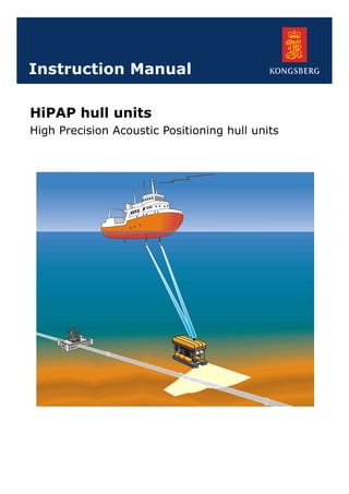
  • 1. HiPAP hull units High Precision Acoustic Positioning hull units Instruction Manual
  • 2.
  • 3. HiPAP hull units High Precision Acoustic Positioning hull units Instruction Manual 857--160639
  • 4. Note Kongsberg Maritime AS makes every effort to ensure that the information contained within this document is correct. However, our equipment is continuously being improved and updated, so we cannot assume liability for any errors which may occur. Warning The equipment to which this manual applies must only be used for the purpose for which it was designed. Improper use or maintenance may cause damage to the equipment or injury to personnel. The user must be familiar with the contents of the appropriate manuals before attempting to install, operate or maintain the equipment. Kongsberg Maritime AS disclaims any responsibility for damage or injury caused by improper installation, use or maintenance of the equipment. Copyright E 2003 Kongsberg Maritime AS The information contained within this document remains the sole property of Kongsberg Maritime AS. No part of this document may be copied or reproduced in any form or by any means, and the information contained within is not to be communicated to a third party, without the prior written consent of Kongsberg Maritime AS. Contact information Support: ui@kongsberg.com Sales: subsea@kongsberg.com Strandpromenaden 50 P.O.Box 111 N-3191 Horten, Norway
  • 5. Instruction Manual I857-160639 / O Sections This book is the Instruction Manual for the HiPAP hull units system. It describes how to operate, to install and to maintain the various units used by the HiPAP hull units system. 1 Introduction 2 System description 3 Operation 4 Maintenance 5 Equipment handling 6 Installation 7 Technical specification 8 Cable layout and interconnections 9 Spare parts 10 HiPAP/HPR Test and alignment procedures 11 Drawing file 12 Index
  • 6. HiPAP hull units II 857-160639 / O Remarks References Further information about the HiPAP system may be found in the following manuals: • APOS HiPAP Instruction manual • HiPAP Instruction manual The reader The maintenance information in this manual is intended to be used by a trained maintenance technician or engineer, with experience of electronic and digital circuitry, computers and electromechanical design. The level of information is based on Kongsberg Maritime’s maintenance philosophy: The onboard technical personnel shall, with the help of the documentation and the system’s built-in test functions, be able to identify malfunctions, locate the fault, and replace major parts, modules and components on the “Line Replaceable Unit” (LRU) level. He/she will however not attempt to repair the LRUs. The installation information in this manual is intended for the design and installation engineers at the shipyard performing the installation. The information is supplied as the basis for the shipyard’s own installation drawings applicable to the vessel. On completion of the installation, this section may be used for reference purposes during system maintenance. Note Distributed copies of this manual will not be updated. If your system software is updated, you will be provided with copies of the latest revision of the manual.
  • 7. Instruction Manual III857-160639 / O Contents INTRODUCTION 1.............................................. Manual content 1. . . . . . . . . . . . . . . . . . . . . . . . . . . . . . . . . . . . . . . . . . . . . . . . Abbreviations 1. . . . . . . . . . . . . . . . . . . . . . . . . . . . . . . . . . . . . . . . . . . . . . . . . General guidelines 1. . . . . . . . . . . . . . . . . . . . . . . . . . . . . . . . . . . . . . . . . . . . . Installation 1. . . . . . . . . . . . . . . . . . . . . . . . . . . . . . . . . . . . . . . . . . . . . . Maintenance 2. . . . . . . . . . . . . . . . . . . . . . . . . . . . . . . . . . . . . . . . . . . . Supply conditions 3. . . . . . . . . . . . . . . . . . . . . . . . . . . . . . . . . . . . . . . . . . . . . . Equipment responsibility 3. . . . . . . . . . . . . . . . . . . . . . . . . . . . . . . . . . Reception, unpacking and storage 3. . . . . . . . . . . . . . . . . . . . . . . . . . . . Project management 3. . . . . . . . . . . . . . . . . . . . . . . . . . . . . . . . . . . . . . Installation, supervision and commissioning 4. . . . . . . . . . . . . . . . . . . Guarantee period 5. . . . . . . . . . . . . . . . . . . . . . . . . . . . . . . . . . . . . . . . . SYSTEM DESCRIPTION 6...................................... Purpose 6. . . . . . . . . . . . . . . . . . . . . . . . . . . . . . . . . . . . . . . . . . . . . . . . . . . . . . Overview 6. . . . . . . . . . . . . . . . . . . . . . . . . . . . . . . . . . . . . . . . . . . . . . . . . . . . HiPAP 500 7. . . . . . . . . . . . . . . . . . . . . . . . . . . . . . . . . . . . . . . . . . . . . . HiPAP 350 8. . . . . . . . . . . . . . . . . . . . . . . . . . . . . . . . . . . . . . . . . . . . . . Hull unit system 9. . . . . . . . . . . . . . . . . . . . . . . . . . . . . . . . . . . . . . . . . . . . . . . Hoist motor and gearbox 12. . . . . . . . . . . . . . . . . . . . . . . . . . . . . . . . . . . . . . . . Gantry 12. . . . . . . . . . . . . . . . . . . . . . . . . . . . . . . . . . . . . . . . . . . . . . . . . . . . . . . Shaft sleeve 12. . . . . . . . . . . . . . . . . . . . . . . . . . . . . . . . . . . . . . . . . . . . . . . . . . . Transducer dock 13. . . . . . . . . . . . . . . . . . . . . . . . . . . . . . . . . . . . . . . . . . . . . . . Mounting flange 13. . . . . . . . . . . . . . . . . . . . . . . . . . . . . . . . . . . . . . . . . . . . . . . Transducer shaft 13. . . . . . . . . . . . . . . . . . . . . . . . . . . . . . . . . . . . . . . . . . . . . . . Transducer 13. . . . . . . . . . . . . . . . . . . . . . . . . . . . . . . . . . . . . . . . . . . . . . . . . . . Gate valve 14. . . . . . . . . . . . . . . . . . . . . . . . . . . . . . . . . . . . . . . . . . . . . . . . . . . . Gate valve position indicator 14. . . . . . . . . . . . . . . . . . . . . . . . . . . . . . . Hoist Control Unit 15. . . . . . . . . . . . . . . . . . . . . . . . . . . . . . . . . . . . . . . . . . . . . Introduction 15. . . . . . . . . . . . . . . . . . . . . . . . . . . . . . . . . . . . . . . . . . . . . External connections 15. . . . . . . . . . . . . . . . . . . . . . . . . . . . . . . . . . . . . . Remote Control Unit 16. . . . . . . . . . . . . . . . . . . . . . . . . . . . . . . . . . . . . . . . . . . General 16. . . . . . . . . . . . . . . . . . . . . . . . . . . . . . . . . . . . . . . . . . . . . . . . External connections 16. . . . . . . . . . . . . . . . . . . . . . . . . . . . . . . . . . . . . . Electrical system 17. . . . . . . . . . . . . . . . . . . . . . . . . . . . . . . . . . . . . . . . . . . . . . . Introduction 17. . . . . . . . . . . . . . . . . . . . . . . . . . . . . . . . . . . . . . . . . . . . . Circuit description 17. . . . . . . . . . . . . . . . . . . . . . . . . . . . . . . . . . . . . . . . Electrical actuator (option) 28. . . . . . . . . . . . . . . . . . . . . . . . . . . . . . . . . . . . . . . General 28. . . . . . . . . . . . . . . . . . . . . . . . . . . . . . . . . . . . . . . . . . . . . . . . System 28. . . . . . . . . . . . . . . . . . . . . . . . . . . . . . . . . . . . . . . . . . . . . . . . . Local control unit 29. . . . . . . . . . . . . . . . . . . . . . . . . . . . . . . . . . . . . . . . Remote station 31. . . . . . . . . . . . . . . . . . . . . . . . . . . . . . . . . . . . . . . . . . . Electrical connections 32. . . . . . . . . . . . . . . . . . . . . . . . . . . . . . . . . . . . .
  • 8. HiPAP hull units IV 857-160639 / O OPERATION 33.................................................. Overview 33. . . . . . . . . . . . . . . . . . . . . . . . . . . . . . . . . . . . . . . . . . . . . . . . . . . . Hoist control operation 34. . . . . . . . . . . . . . . . . . . . . . . . . . . . . . . . . . . . . . . . . . General 34. . . . . . . . . . . . . . . . . . . . . . . . . . . . . . . . . . . . . . . . . . . . . . . . Lowering the hull unit 35. . . . . . . . . . . . . . . . . . . . . . . . . . . . . . . . . . . . . Raising the hull unit 35. . . . . . . . . . . . . . . . . . . . . . . . . . . . . . . . . . . . . . Stopping the hull unit 35. . . . . . . . . . . . . . . . . . . . . . . . . . . . . . . . . . . . . Remote operation of the hull unit 35. . . . . . . . . . . . . . . . . . . . . . . . . . . . Remote control operation 36. . . . . . . . . . . . . . . . . . . . . . . . . . . . . . . . . . . . . . . . Control buttons 37. . . . . . . . . . . . . . . . . . . . . . . . . . . . . . . . . . . . . . . . . . Indicator lamps 37. . . . . . . . . . . . . . . . . . . . . . . . . . . . . . . . . . . . . . . . . . Motor reset 37. . . . . . . . . . . . . . . . . . . . . . . . . . . . . . . . . . . . . . . . . . . . . Manual operation of the hoist motor 38. . . . . . . . . . . . . . . . . . . . . . . . . . . . . . . Procedure 38. . . . . . . . . . . . . . . . . . . . . . . . . . . . . . . . . . . . . . . . . . . . . . . Gate valve operation 40. . . . . . . . . . . . . . . . . . . . . . . . . . . . . . . . . . . . . . . . . . . . General 40. . . . . . . . . . . . . . . . . . . . . . . . . . . . . . . . . . . . . . . . . . . . . . . . Manual operation 40. . . . . . . . . . . . . . . . . . . . . . . . . . . . . . . . . . . . . . . . Using the actuator remote control unit 41. . . . . . . . . . . . . . . . . . . . . . . . MAINTENANCE 42............................................... Overview 42. . . . . . . . . . . . . . . . . . . . . . . . . . . . . . . . . . . . . . . . . . . . . . . . . . . . Safety 42. . . . . . . . . . . . . . . . . . . . . . . . . . . . . . . . . . . . . . . . . . . . . . . . . . . . . . . Watertightness test 42. . . . . . . . . . . . . . . . . . . . . . . . . . . . . . . . . . . . . . . . . . . . . Torques 43. . . . . . . . . . . . . . . . . . . . . . . . . . . . . . . . . . . . . . . . . . . . . . . . . . . . . . Tools 44. . . . . . . . . . . . . . . . . . . . . . . . . . . . . . . . . . . . . . . . . . . . . . . . . . . . . . . . Standard tools 44. . . . . . . . . . . . . . . . . . . . . . . . . . . . . . . . . . . . . . . . . . . Special tools 44. . . . . . . . . . . . . . . . . . . . . . . . . . . . . . . . . . . . . . . . . . . . Before you start 45. . . . . . . . . . . . . . . . . . . . . . . . . . . . . . . . . . . . . . . . . . . . . . . Preventive maintenance schedule 45. . . . . . . . . . . . . . . . . . . . . . . . . . . . . . . . . . General 45. . . . . . . . . . . . . . . . . . . . . . . . . . . . . . . . . . . . . . . . . . . . . . . . Maintenance chart 45. . . . . . . . . . . . . . . . . . . . . . . . . . . . . . . . . . . . . . . . Lubrication 45. . . . . . . . . . . . . . . . . . . . . . . . . . . . . . . . . . . . . . . . . . . . . Special attention 46. . . . . . . . . . . . . . . . . . . . . . . . . . . . . . . . . . . . . . . . . Hull unit general inspection 47. . . . . . . . . . . . . . . . . . . . . . . . . . . . . . . . . . . . . . General 47. . . . . . . . . . . . . . . . . . . . . . . . . . . . . . . . . . . . . . . . . . . . . . . . Logistics 47. . . . . . . . . . . . . . . . . . . . . . . . . . . . . . . . . . . . . . . . . . . . . . . Procedure 47. . . . . . . . . . . . . . . . . . . . . . . . . . . . . . . . . . . . . . . . . . . . . . . Hoist Control Unit 49. . . . . . . . . . . . . . . . . . . . . . . . . . . . . . . . . . . . . . . . . . . . . Internal layout 49. . . . . . . . . . . . . . . . . . . . . . . . . . . . . . . . . . . . . . . . . . . Hoist Control Unit inspection 50. . . . . . . . . . . . . . . . . . . . . . . . . . . . . . . Remote Control Unit 52. . . . . . . . . . . . . . . . . . . . . . . . . . . . . . . . . . . . . . . . . . . Internal layout 52. . . . . . . . . . . . . . . . . . . . . . . . . . . . . . . . . . . . . . . . . . . Remote Control Unit inspection 53. . . . . . . . . . . . . . . . . . . . . . . . . . . . . Watertightness test 55. . . . . . . . . . . . . . . . . . . . . . . . . . . . . . . . . . . . . . . . . . . . . Logistics 55. . . . . . . . . . . . . . . . . . . . . . . . . . . . . . . . . . . . . . . . . . . . . . . Procedure 55. . . . . . . . . . . . . . . . . . . . . . . . . . . . . . . . . . . . . . . . . . . . . . .
  • 9. Instruction Manual V857-160639 / O Corrective maintenance 56. . . . . . . . . . . . . . . . . . . . . . . . . . . . . . . . . . . . . . . . . Overview 56. . . . . . . . . . . . . . . . . . . . . . . . . . . . . . . . . . . . . . . . . . . . . . . General 56. . . . . . . . . . . . . . . . . . . . . . . . . . . . . . . . . . . . . . . . . . . . . . . . Hoist motor, gear box lubrication 57. . . . . . . . . . . . . . . . . . . . . . . . . . . . . . . . . . Logistics 57. . . . . . . . . . . . . . . . . . . . . . . . . . . . . . . . . . . . . . . . . . . . . . . Procedure 57. . . . . . . . . . . . . . . . . . . . . . . . . . . . . . . . . . . . . . . . . . . . . . . Hoist motor, replacement 58. . . . . . . . . . . . . . . . . . . . . . . . . . . . . . . . . . . . . . . . Logistics 58. . . . . . . . . . . . . . . . . . . . . . . . . . . . . . . . . . . . . . . . . . . . . . . Procedure 58. . . . . . . . . . . . . . . . . . . . . . . . . . . . . . . . . . . . . . . . . . . . . . . Hoist motor, gear box replacement 59. . . . . . . . . . . . . . . . . . . . . . . . . . . . . . . . Logistics 59. . . . . . . . . . . . . . . . . . . . . . . . . . . . . . . . . . . . . . . . . . . . . . . Procedure 59. . . . . . . . . . . . . . . . . . . . . . . . . . . . . . . . . . . . . . . . . . . . . . . Drive chains, lubrication 61. . . . . . . . . . . . . . . . . . . . . . . . . . . . . . . . . . . . . . . . Logistics 61. . . . . . . . . . . . . . . . . . . . . . . . . . . . . . . . . . . . . . . . . . . . . . . Procedure 61. . . . . . . . . . . . . . . . . . . . . . . . . . . . . . . . . . . . . . . . . . . . . . . Drive chains, tension 61. . . . . . . . . . . . . . . . . . . . . . . . . . . . . . . . . . . . . . . . . . . Logistics 61. . . . . . . . . . . . . . . . . . . . . . . . . . . . . . . . . . . . . . . . . . . . . . . Test procedure 62. . . . . . . . . . . . . . . . . . . . . . . . . . . . . . . . . . . . . . . . . . . Adjusting the tension 63. . . . . . . . . . . . . . . . . . . . . . . . . . . . . . . . . . . . . Drive chains, replacement 63. . . . . . . . . . . . . . . . . . . . . . . . . . . . . . . . . . . . . . . Logistics 63. . . . . . . . . . . . . . . . . . . . . . . . . . . . . . . . . . . . . . . . . . . . . . . Procedure 63. . . . . . . . . . . . . . . . . . . . . . . . . . . . . . . . . . . . . . . . . . . . . . . Opening the service dock 64. . . . . . . . . . . . . . . . . . . . . . . . . . . . . . . . . . . . . . . . Logistics 64. . . . . . . . . . . . . . . . . . . . . . . . . . . . . . . . . . . . . . . . . . . . . . . Procedure 64. . . . . . . . . . . . . . . . . . . . . . . . . . . . . . . . . . . . . . . . . . . . . . . Lifting the hull unit 65. . . . . . . . . . . . . . . . . . . . . . . . . . . . . . . . . . . . . . . . . . . . Logistics 65. . . . . . . . . . . . . . . . . . . . . . . . . . . . . . . . . . . . . . . . . . . . . . . Procedure 65. . . . . . . . . . . . . . . . . . . . . . . . . . . . . . . . . . . . . . . . . . . . . . . Transducer, replacement 67. . . . . . . . . . . . . . . . . . . . . . . . . . . . . . . . . . . . . . . . . Logistics 67. . . . . . . . . . . . . . . . . . . . . . . . . . . . . . . . . . . . . . . . . . . . . . . Procedure 67. . . . . . . . . . . . . . . . . . . . . . . . . . . . . . . . . . . . . . . . . . . . . . . Transducer, marine growth removal 69. . . . . . . . . . . . . . . . . . . . . . . . . . . . . . . . Logistics 69. . . . . . . . . . . . . . . . . . . . . . . . . . . . . . . . . . . . . . . . . . . . . . . Procedure 69. . . . . . . . . . . . . . . . . . . . . . . . . . . . . . . . . . . . . . . . . . . . . . . HiPAP 500 transducer cable, replacement 70. . . . . . . . . . . . . . . . . . . . . . . . . . . Logistics 70. . . . . . . . . . . . . . . . . . . . . . . . . . . . . . . . . . . . . . . . . . . . . . . Procedure 70. . . . . . . . . . . . . . . . . . . . . . . . . . . . . . . . . . . . . . . . . . . . . . . HiPAP 350 transducer cables, replacement 73. . . . . . . . . . . . . . . . . . . . . . . . . . Logistics 73. . . . . . . . . . . . . . . . . . . . . . . . . . . . . . . . . . . . . . . . . . . . . . . Cable 1 73. . . . . . . . . . . . . . . . . . . . . . . . . . . . . . . . . . . . . . . . . . . . . . . . Cable 2 76. . . . . . . . . . . . . . . . . . . . . . . . . . . . . . . . . . . . . . . . . . . . . . . . Shaft sleeve, lubrication 77. . . . . . . . . . . . . . . . . . . . . . . . . . . . . . . . . . . . . . . . . Logistics 77. . . . . . . . . . . . . . . . . . . . . . . . . . . . . . . . . . . . . . . . . . . . . . . Procedure 77. . . . . . . . . . . . . . . . . . . . . . . . . . . . . . . . . . . . . . . . . . . . . . .
  • 10. HiPAP hull units VI 857-160639 / O Shaft sleeve, disassembly 78. . . . . . . . . . . . . . . . . . . . . . . . . . . . . . . . . . . . . . . . Logistics 78. . . . . . . . . . . . . . . . . . . . . . . . . . . . . . . . . . . . . . . . . . . . . . . Procedure 78. . . . . . . . . . . . . . . . . . . . . . . . . . . . . . . . . . . . . . . . . . . . . . . Zinc anode, inspection and replacement 81. . . . . . . . . . . . . . . . . . . . . . . . . . . . Logistics 81. . . . . . . . . . . . . . . . . . . . . . . . . . . . . . . . . . . . . . . . . . . . . . . Procedure 81. . . . . . . . . . . . . . . . . . . . . . . . . . . . . . . . . . . . . . . . . . . . . . . Transducer shaft, guide rails adjustment 82. . . . . . . . . . . . . . . . . . . . . . . . . . . . Logistics 82. . . . . . . . . . . . . . . . . . . . . . . . . . . . . . . . . . . . . . . . . . . . . . . Procedure 82. . . . . . . . . . . . . . . . . . . . . . . . . . . . . . . . . . . . . . . . . . . . . . . Limit switches, replacement 83. . . . . . . . . . . . . . . . . . . . . . . . . . . . . . . . . . . . . . Logistics 83. . . . . . . . . . . . . . . . . . . . . . . . . . . . . . . . . . . . . . . . . . . . . . . Procedure 83. . . . . . . . . . . . . . . . . . . . . . . . . . . . . . . . . . . . . . . . . . . . . . . Gate valve, replacement 84. . . . . . . . . . . . . . . . . . . . . . . . . . . . . . . . . . . . . . . . . General 84. . . . . . . . . . . . . . . . . . . . . . . . . . . . . . . . . . . . . . . . . . . . . . . . Logistics 84. . . . . . . . . . . . . . . . . . . . . . . . . . . . . . . . . . . . . . . . . . . . . . . Procedure 84. . . . . . . . . . . . . . . . . . . . . . . . . . . . . . . . . . . . . . . . . . . . . . . Gate valve position indicator, replacement 86. . . . . . . . . . . . . . . . . . . . . Position indicator switch unit, replacement 87. . . . . . . . . . . . . . . . . . . . Hoist Control Unit 88. . . . . . . . . . . . . . . . . . . . . . . . . . . . . . . . . . . . . . . . . . . . . General 88. . . . . . . . . . . . . . . . . . . . . . . . . . . . . . . . . . . . . . . . . . . . . . . . Logistics 88. . . . . . . . . . . . . . . . . . . . . . . . . . . . . . . . . . . . . . . . . . . . . . . References 88. . . . . . . . . . . . . . . . . . . . . . . . . . . . . . . . . . . . . . . . . . . . . . Replacement of Hoist Control Unit parts 89. . . . . . . . . . . . . . . . . . . . . . Remote Control Unit 90. . . . . . . . . . . . . . . . . . . . . . . . . . . . . . . . . . . . . . . . . . . General 90. . . . . . . . . . . . . . . . . . . . . . . . . . . . . . . . . . . . . . . . . . . . . . . . Logistics 90. . . . . . . . . . . . . . . . . . . . . . . . . . . . . . . . . . . . . . . . . . . . . . . References 90. . . . . . . . . . . . . . . . . . . . . . . . . . . . . . . . . . . . . . . . . . . . . . Replacement of Remote Control Unit parts 91. . . . . . . . . . . . . . . . . . . . Electrical actuator (option) 93. . . . . . . . . . . . . . . . . . . . . . . . . . . . . . . . . . . . . . . Logistics 93. . . . . . . . . . . . . . . . . . . . . . . . . . . . . . . . . . . . . . . . . . . . . . . References 93. . . . . . . . . . . . . . . . . . . . . . . . . . . . . . . . . . . . . . . . . . . . . . Inspection 93. . . . . . . . . . . . . . . . . . . . . . . . . . . . . . . . . . . . . . . . . . . . . . Lubrication 93. . . . . . . . . . . . . . . . . . . . . . . . . . . . . . . . . . . . . . . . . . . . . Electrical connections 93. . . . . . . . . . . . . . . . . . . . . . . . . . . . . . . . . . . . . Actuator local control unit, inspection 94. . . . . . . . . . . . . . . . . . . . . . . . Actuator remote station, inspection 95. . . . . . . . . . . . . . . . . . . . . . . . . . Replacement of remote station and local control unit parts 96. . . . . . . . Test procedure 99. . . . . . . . . . . . . . . . . . . . . . . . . . . . . . . . . . . . . . . . . . . . . . . . General checks 99. . . . . . . . . . . . . . . . . . . . . . . . . . . . . . . . . . . . . . . . . . System alignment 99. . . . . . . . . . . . . . . . . . . . . . . . . . . . . . . . . . . . . . . .
  • 11. Instruction Manual VII857-160639 / O EQUIPMENT HANDLING 100..................................... Introduction 100. . . . . . . . . . . . . . . . . . . . . . . . . . . . . . . . . . . . . . . . . . . . . . . . . . Transportation 100. . . . . . . . . . . . . . . . . . . . . . . . . . . . . . . . . . . . . . . . . . . . . . . . . General specifications 100. . . . . . . . . . . . . . . . . . . . . . . . . . . . . . . . . . . . . Local transportation 100. . . . . . . . . . . . . . . . . . . . . . . . . . . . . . . . . . . . . . Initial preservation 101. . . . . . . . . . . . . . . . . . . . . . . . . . . . . . . . . . . . . . . . . . . . . Inspection and unpacking 103. . . . . . . . . . . . . . . . . . . . . . . . . . . . . . . . . . . . . . . . Storage 105. . . . . . . . . . . . . . . . . . . . . . . . . . . . . . . . . . . . . . . . . . . . . . . . . . . . . . After use storage 106. . . . . . . . . . . . . . . . . . . . . . . . . . . . . . . . . . . . . . . . . Re-packing 108. . . . . . . . . . . . . . . . . . . . . . . . . . . . . . . . . . . . . . . . . . . . . ESD precautions 108. . . . . . . . . . . . . . . . . . . . . . . . . . . . . . . . . . . . . . . . . . . . . . . Temperature protection 109. . . . . . . . . . . . . . . . . . . . . . . . . . . . . . . . . . . . . . . . . . INSTALLATION 110............................................... Overview 110. . . . . . . . . . . . . . . . . . . . . . . . . . . . . . . . . . . . . . . . . . . . . . . . . . . . Configuration 110. . . . . . . . . . . . . . . . . . . . . . . . . . . . . . . . . . . . . . . . . . . . . . . . . Installation procedures overview 111. . . . . . . . . . . . . . . . . . . . . . . . . . . . . . . . . . Installation requirements 112. . . . . . . . . . . . . . . . . . . . . . . . . . . . . . . . . . . . . . . . Supply power 112. . . . . . . . . . . . . . . . . . . . . . . . . . . . . . . . . . . . . . . . . . . Environmental requirements 112. . . . . . . . . . . . . . . . . . . . . . . . . . . . . . . . Sonar room requirements 113. . . . . . . . . . . . . . . . . . . . . . . . . . . . . . . . . . . . . . . . General 113. . . . . . . . . . . . . . . . . . . . . . . . . . . . . . . . . . . . . . . . . . . . . . . . Ventilation 113. . . . . . . . . . . . . . . . . . . . . . . . . . . . . . . . . . . . . . . . . . . . . . Bilge pump system 113. . . . . . . . . . . . . . . . . . . . . . . . . . . . . . . . . . . . . . . Precautions and requirements 114. . . . . . . . . . . . . . . . . . . . . . . . . . . . . . . . . . . . . General installation information 115. . . . . . . . . . . . . . . . . . . . . . . . . . . . . . . . . . . Introduction 115. . . . . . . . . . . . . . . . . . . . . . . . . . . . . . . . . . . . . . . . . . . . . References 115. . . . . . . . . . . . . . . . . . . . . . . . . . . . . . . . . . . . . . . . . . . . . . Logistics 115. . . . . . . . . . . . . . . . . . . . . . . . . . . . . . . . . . . . . . . . . . . . . . . Choice of location 115. . . . . . . . . . . . . . . . . . . . . . . . . . . . . . . . . . . . . . . . Additional points 116. . . . . . . . . . . . . . . . . . . . . . . . . . . . . . . . . . . . . . . . . Installation of the mounting flange 118. . . . . . . . . . . . . . . . . . . . . . . . . . . . . . . . General 118. . . . . . . . . . . . . . . . . . . . . . . . . . . . . . . . . . . . . . . . . . . . . . . . DN500 mounting flange 118. . . . . . . . . . . . . . . . . . . . . . . . . . . . . . . . . . . DN350 mounting flange 118. . . . . . . . . . . . . . . . . . . . . . . . . . . . . . . . . . . Installation accuracy and tolerances 119. . . . . . . . . . . . . . . . . . . . . . . . . . Logistics 119. . . . . . . . . . . . . . . . . . . . . . . . . . . . . . . . . . . . . . . . . . . . . . . References 119. . . . . . . . . . . . . . . . . . . . . . . . . . . . . . . . . . . . . . . . . . . . . . Installation procedure 120. . . . . . . . . . . . . . . . . . . . . . . . . . . . . . . . . . . . .
  • 12. HiPAP hull units VIII 857-160639 / O Installation of a gate valve 121. . . . . . . . . . . . . . . . . . . . . . . . . . . . . . . . . . . . . . . Introduction 121. . . . . . . . . . . . . . . . . . . . . . . . . . . . . . . . . . . . . . . . . . . . . Location of the unit 121. . . . . . . . . . . . . . . . . . . . . . . . . . . . . . . . . . . . . . . Logistics 121. . . . . . . . . . . . . . . . . . . . . . . . . . . . . . . . . . . . . . . . . . . . . . . References 121. . . . . . . . . . . . . . . . . . . . . . . . . . . . . . . . . . . . . . . . . . . . . . O-ring and flange gasket 121. . . . . . . . . . . . . . . . . . . . . . . . . . . . . . . . . . . Procedure 122. . . . . . . . . . . . . . . . . . . . . . . . . . . . . . . . . . . . . . . . . . . . . . . Installation of the gantry 123. . . . . . . . . . . . . . . . . . . . . . . . . . . . . . . . . . . . . . . . General 123. . . . . . . . . . . . . . . . . . . . . . . . . . . . . . . . . . . . . . . . . . . . . . . . References 123. . . . . . . . . . . . . . . . . . . . . . . . . . . . . . . . . . . . . . . . . . . . . . Logistics 123. . . . . . . . . . . . . . . . . . . . . . . . . . . . . . . . . . . . . . . . . . . . . . . Procedure 123. . . . . . . . . . . . . . . . . . . . . . . . . . . . . . . . . . . . . . . . . . . . . . . Mounting the hoist motor 125. . . . . . . . . . . . . . . . . . . . . . . . . . . . . . . . . . . . . . . . Introduction 125. . . . . . . . . . . . . . . . . . . . . . . . . . . . . . . . . . . . . . . . . . . . . Procedure 125. . . . . . . . . . . . . . . . . . . . . . . . . . . . . . . . . . . . . . . . . . . . . . . Hull unit surface protection 126. . . . . . . . . . . . . . . . . . . . . . . . . . . . . . . . . . . . . . General 126. . . . . . . . . . . . . . . . . . . . . . . . . . . . . . . . . . . . . . . . . . . . . . . . Logistics 126. . . . . . . . . . . . . . . . . . . . . . . . . . . . . . . . . . . . . . . . . . . . . . . Installation of the Hoist Control Unit 127. . . . . . . . . . . . . . . . . . . . . . . . . . . . . . . Introduction 127. . . . . . . . . . . . . . . . . . . . . . . . . . . . . . . . . . . . . . . . . . . . . Unit location 127. . . . . . . . . . . . . . . . . . . . . . . . . . . . . . . . . . . . . . . . . . . . Logistics 127. . . . . . . . . . . . . . . . . . . . . . . . . . . . . . . . . . . . . . . . . . . . . . . References 127. . . . . . . . . . . . . . . . . . . . . . . . . . . . . . . . . . . . . . . . . . . . . . Procedure 128. . . . . . . . . . . . . . . . . . . . . . . . . . . . . . . . . . . . . . . . . . . . . . . Installation of the Remote Control Unit 129. . . . . . . . . . . . . . . . . . . . . . . . . . . . . General 129. . . . . . . . . . . . . . . . . . . . . . . . . . . . . . . . . . . . . . . . . . . . . . . . Location of the unit 129. . . . . . . . . . . . . . . . . . . . . . . . . . . . . . . . . . . . . . . Logistics 129. . . . . . . . . . . . . . . . . . . . . . . . . . . . . . . . . . . . . . . . . . . . . . . References 129. . . . . . . . . . . . . . . . . . . . . . . . . . . . . . . . . . . . . . . . . . . . . . Installation procedure 129. . . . . . . . . . . . . . . . . . . . . . . . . . . . . . . . . . . . . Pin allocations 130. . . . . . . . . . . . . . . . . . . . . . . . . . . . . . . . . . . . . . . . . . . Electrical actuator (option) 131. . . . . . . . . . . . . . . . . . . . . . . . . . . . . . . . . . . . . . . General 131. . . . . . . . . . . . . . . . . . . . . . . . . . . . . . . . . . . . . . . . . . . . . . . . Location of the unit 131. . . . . . . . . . . . . . . . . . . . . . . . . . . . . . . . . . . . . . . Logistics 131. . . . . . . . . . . . . . . . . . . . . . . . . . . . . . . . . . . . . . . . . . . . . . . References 131. . . . . . . . . . . . . . . . . . . . . . . . . . . . . . . . . . . . . . . . . . . . . . Mounting procedure 131. . . . . . . . . . . . . . . . . . . . . . . . . . . . . . . . . . . . . . Switch settings 132. . . . . . . . . . . . . . . . . . . . . . . . . . . . . . . . . . . . . . . . . . Wiring diagrams 133. . . . . . . . . . . . . . . . . . . . . . . . . . . . . . . . . . . . . . . . . Installation of the remote station 134. . . . . . . . . . . . . . . . . . . . . . . . . . . . . Installation of the local control unit 135. . . . . . . . . . . . . . . . . . . . . . . . . . . . . . . . General 135. . . . . . . . . . . . . . . . . . . . . . . . . . . . . . . . . . . . . . . . . . . . . . . . Location of the unit 135. . . . . . . . . . . . . . . . . . . . . . . . . . . . . . . . . . . . . . . Logistics 135. . . . . . . . . . . . . . . . . . . . . . . . . . . . . . . . . . . . . . . . . . . . . . . References 135. . . . . . . . . . . . . . . . . . . . . . . . . . . . . . . . . . . . . . . . . . . . . . Procedure 135. . . . . . . . . . . . . . . . . . . . . . . . . . . . . . . . . . . . . . . . . . . . . . .
  • 13. Instruction Manual IX857-160639 / O TECHNICAL SPECIFICATION 137................................ Overview 137. . . . . . . . . . . . . . . . . . . . . . . . . . . . . . . . . . . . . . . . . . . . . . . . . . . . Packed dimensions and weights 138. . . . . . . . . . . . . . . . . . . . . . . . . . . . . . . . . . . HiPAP 500 gantry with dock 138. . . . . . . . . . . . . . . . . . . . . . . . . . . . . . . HiPAP 350 gantry with dock 138. . . . . . . . . . . . . . . . . . . . . . . . . . . . . . . Hull units outline dimensions 139. . . . . . . . . . . . . . . . . . . . . . . . . . . . . . . . . . . . . HiPAP 500 139. . . . . . . . . . . . . . . . . . . . . . . . . . . . . . . . . . . . . . . . . . . . . . HiPAP 350 139. . . . . . . . . . . . . . . . . . . . . . . . . . . . . . . . . . . . . . . . . . . . . . 500 mm mounting flange 140. . . . . . . . . . . . . . . . . . . . . . . . . . . . . . . . . . 500 mm gate valve 140. . . . . . . . . . . . . . . . . . . . . . . . . . . . . . . . . . . . . . . 350 mm mounting flange 141. . . . . . . . . . . . . . . . . . . . . . . . . . . . . . . . . . 350 mm gate valve 141. . . . . . . . . . . . . . . . . . . . . . . . . . . . . . . . . . . . . . . Gantry 142. . . . . . . . . . . . . . . . . . . . . . . . . . . . . . . . . . . . . . . . . . . . . . . . . Lubrication 143. . . . . . . . . . . . . . . . . . . . . . . . . . . . . . . . . . . . . . . . . . . . . . . . . . . Equivalents 143. . . . . . . . . . . . . . . . . . . . . . . . . . . . . . . . . . . . . . . . . . . . . Hoist Control Unit 144. . . . . . . . . . . . . . . . . . . . . . . . . . . . . . . . . . . . . . . . . . . . . General 144. . . . . . . . . . . . . . . . . . . . . . . . . . . . . . . . . . . . . . . . . . . . . . . . Unit dimensions 144. . . . . . . . . . . . . . . . . . . . . . . . . . . . . . . . . . . . . . . . . Power supply 144. . . . . . . . . . . . . . . . . . . . . . . . . . . . . . . . . . . . . . . . . . . . Environment 144. . . . . . . . . . . . . . . . . . . . . . . . . . . . . . . . . . . . . . . . . . . . Remote Control Unit 147. . . . . . . . . . . . . . . . . . . . . . . . . . . . . . . . . . . . . . . . . . . Unit dimensions 147. . . . . . . . . . . . . . . . . . . . . . . . . . . . . . . . . . . . . . . . . Power supply 147. . . . . . . . . . . . . . . . . . . . . . . . . . . . . . . . . . . . . . . . . . . . Environment 147. . . . . . . . . . . . . . . . . . . . . . . . . . . . . . . . . . . . . . . . . . . . Cabling 147. . . . . . . . . . . . . . . . . . . . . . . . . . . . . . . . . . . . . . . . . . . . . . . . Raise and lower motor 149. . . . . . . . . . . . . . . . . . . . . . . . . . . . . . . . . . . . . . . . . . Transducers 150. . . . . . . . . . . . . . . . . . . . . . . . . . . . . . . . . . . . . . . . . . . . . . . . . . . HiPAP 500 150. . . . . . . . . . . . . . . . . . . . . . . . . . . . . . . . . . . . . . . . . . . . . . HiPAP 350 150. . . . . . . . . . . . . . . . . . . . . . . . . . . . . . . . . . . . . . . . . . . . . . Actuator (option) 151. . . . . . . . . . . . . . . . . . . . . . . . . . . . . . . . . . . . . . . . . . . . . . General 151. . . . . . . . . . . . . . . . . . . . . . . . . . . . . . . . . . . . . . . . . . . . . . . . Unit dimensions 151. . . . . . . . . . . . . . . . . . . . . . . . . . . . . . . . . . . . . . . . . Electrical motor 151. . . . . . . . . . . . . . . . . . . . . . . . . . . . . . . . . . . . . . . . . . Remote station 151. . . . . . . . . . . . . . . . . . . . . . . . . . . . . . . . . . . . . . . . . . . Local control unit 151. . . . . . . . . . . . . . . . . . . . . . . . . . . . . . . . . . . . . . . . Environment temperature 151. . . . . . . . . . . . . . . . . . . . . . . . . . . . . . . . . .
  • 14. HiPAP hull units X 857-160639 / O CABLE LAYOUT AND INTERCONNECTIONS 152................. Overview 152. . . . . . . . . . . . . . . . . . . . . . . . . . . . . . . . . . . . . . . . . . . . . . . . . . . . Cable gland assembly procedure 153. . . . . . . . . . . . . . . . . . . . . . . . . . . . . . . . . . Purpose 153. . . . . . . . . . . . . . . . . . . . . . . . . . . . . . . . . . . . . . . . . . . . . . . . General procedure 153. . . . . . . . . . . . . . . . . . . . . . . . . . . . . . . . . . . . . . . . Securing and terminating the cables 154. . . . . . . . . . . . . . . . . . . . . . . . . . Multi-diameter modules 154. . . . . . . . . . . . . . . . . . . . . . . . . . . . . . . . . . . Standard type 157. . . . . . . . . . . . . . . . . . . . . . . . . . . . . . . . . . . . . . . . . . . . Additional type 1 (842-093878) 159. . . . . . . . . . . . . . . . . . . . . . . . . . . . . Additional type 2 (541-093642) 159. . . . . . . . . . . . . . . . . . . . . . . . . . . . . Basic cabling requirements 161. . . . . . . . . . . . . . . . . . . . . . . . . . . . . . . . . . . . . . . HiPAP cable plan 164. . . . . . . . . . . . . . . . . . . . . . . . . . . . . . . . . . . . . . . . . . . . . . Cable specifications 165. . . . . . . . . . . . . . . . . . . . . . . . . . . . . . . . . . . . . . . . . . . . Shipyard cables 165. . . . . . . . . . . . . . . . . . . . . . . . . . . . . . . . . . . . . . . . . . System cables 165. . . . . . . . . . . . . . . . . . . . . . . . . . . . . . . . . . . . . . . . . . . Cable connections 165. . . . . . . . . . . . . . . . . . . . . . . . . . . . . . . . . . . . . . . . . . . . . . Special cables 165. . . . . . . . . . . . . . . . . . . . . . . . . . . . . . . . . . . . . . . . . . . . . . . . . Hull unit cables 166. . . . . . . . . . . . . . . . . . . . . . . . . . . . . . . . . . . . . . . . . . . . . . . . HiPAP 500 system 166. . . . . . . . . . . . . . . . . . . . . . . . . . . . . . . . . . . . . . . HiPAP 350 system 167. . . . . . . . . . . . . . . . . . . . . . . . . . . . . . . . . . . . . . . Cables interconnection 170. . . . . . . . . . . . . . . . . . . . . . . . . . . . . . . . . . . . . . . . . . Cable K 170. . . . . . . . . . . . . . . . . . . . . . . . . . . . . . . . . . . . . . . . . . . . . . . . Cable M 173. . . . . . . . . . . . . . . . . . . . . . . . . . . . . . . . . . . . . . . . . . . . . . . . Cable N 173. . . . . . . . . . . . . . . . . . . . . . . . . . . . . . . . . . . . . . . . . . . . . . . . Cable O 173. . . . . . . . . . . . . . . . . . . . . . . . . . . . . . . . . . . . . . . . . . . . . . . . Cable P 173. . . . . . . . . . . . . . . . . . . . . . . . . . . . . . . . . . . . . . . . . . . . . . . . Cable Q 173. . . . . . . . . . . . . . . . . . . . . . . . . . . . . . . . . . . . . . . . . . . . . . . . Cable Y 174. . . . . . . . . . . . . . . . . . . . . . . . . . . . . . . . . . . . . . . . . . . . . . . . Cable installation 176. . . . . . . . . . . . . . . . . . . . . . . . . . . . . . . . . . . . . . . . . . . . . . Logistics 176. . . . . . . . . . . . . . . . . . . . . . . . . . . . . . . . . . . . . . . . . . . . . . . References 176. . . . . . . . . . . . . . . . . . . . . . . . . . . . . . . . . . . . . . . . . . . . . . Installation procedure 176. . . . . . . . . . . . . . . . . . . . . . . . . . . . . . . . . . . . . Actuator connections (option) 177. . . . . . . . . . . . . . . . . . . . . . . . . . . . . . . . . . . . Cables 177. . . . . . . . . . . . . . . . . . . . . . . . . . . . . . . . . . . . . . . . . . . . . . . . . SPARE PARTS 178................................................. Codes used 178. . . . . . . . . . . . . . . . . . . . . . . . . . . . . . . . . . . . . . . . . . . . . . . . . . . Consumables and repair kits 179. . . . . . . . . . . . . . . . . . . . . . . . . . . . . . . . . . . . . . Main units spare parts list 180. . . . . . . . . . . . . . . . . . . . . . . . . . . . . . . . . . . . . . . . Hull Unit assembly spare parts list 181. . . . . . . . . . . . . . . . . . . . . . . . . . . . . . . . . Chains 182. . . . . . . . . . . . . . . . . . . . . . . . . . . . . . . . . . . . . . . . . . . . . . . . . . . . . . . Chains spare parts list 183. . . . . . . . . . . . . . . . . . . . . . . . . . . . . . . . . . . . . Dock 184. . . . . . . . . . . . . . . . . . . . . . . . . . . . . . . . . . . . . . . . . . . . . . . . . . . . . . . . Dock spare parts list 185. . . . . . . . . . . . . . . . . . . . . . . . . . . . . . . . . . . . . . Transducer shaft sleeve 186. . . . . . . . . . . . . . . . . . . . . . . . . . . . . . . . . . . . . . . . . Transducer shaft sleeve spare parts list 187. . . . . . . . . . . . . . . . . . . . . . . .
  • 15. Instruction Manual XI857-160639 / O Transducer shaft sleeve-top 188. . . . . . . . . . . . . . . . . . . . . . . . . . . . . . . . . . . . . . Transducer 189. . . . . . . . . . . . . . . . . . . . . . . . . . . . . . . . . . . . . . . . . . . . . . . . . . . Standard transducer spare parts list 189. . . . . . . . . . . . . . . . . . . . . . . . . . . Remote Control Unit 190. . . . . . . . . . . . . . . . . . . . . . . . . . . . . . . . . . . . . . . . . . . Remote Control Unit spare parts list 190. . . . . . . . . . . . . . . . . . . . . . . . . . Hoist Control Unit 191. . . . . . . . . . . . . . . . . . . . . . . . . . . . . . . . . . . . . . . . . . . . . Hoist Control Unit spare parts 191. . . . . . . . . . . . . . . . . . . . . . . . . . . . . . TEST AND ALIGNMENT PROCEDURES 192....................... Introduction 193. . . . . . . . . . . . . . . . . . . . . . . . . . . . . . . . . . . . . . . . . . . . . . . . . . Purpose 193. . . . . . . . . . . . . . . . . . . . . . . . . . . . . . . . . . . . . . . . . . . . . . . . Test certificates 193. . . . . . . . . . . . . . . . . . . . . . . . . . . . . . . . . . . . . . . . . . Visual inspections 193. . . . . . . . . . . . . . . . . . . . . . . . . . . . . . . . . . . . . . . . Test and alignments 193. . . . . . . . . . . . . . . . . . . . . . . . . . . . . . . . . . . . . . . Test procedures introduction 194. . . . . . . . . . . . . . . . . . . . . . . . . . . . . . . . Inspection of the hull unit 195. . . . . . . . . . . . . . . . . . . . . . . . . . . . . . . . . . . . . . . . Logistics 195. . . . . . . . . . . . . . . . . . . . . . . . . . . . . . . . . . . . . . . . . . . . . . . Procedure 195. . . . . . . . . . . . . . . . . . . . . . . . . . . . . . . . . . . . . . . . . . . . . . . Test certificate 197. . . . . . . . . . . . . . . . . . . . . . . . . . . . . . . . . . . . . . . . . . . Inspection of the Hoist Control Unit 198. . . . . . . . . . . . . . . . . . . . . . . . . . . . . . . Logistics 198. . . . . . . . . . . . . . . . . . . . . . . . . . . . . . . . . . . . . . . . . . . . . . . Procedure 198. . . . . . . . . . . . . . . . . . . . . . . . . . . . . . . . . . . . . . . . . . . . . . . Test certificate 199. . . . . . . . . . . . . . . . . . . . . . . . . . . . . . . . . . . . . . . . . . . Inspection of the Remote Control Unit 200. . . . . . . . . . . . . . . . . . . . . . . . . . . . . Logistics 200. . . . . . . . . . . . . . . . . . . . . . . . . . . . . . . . . . . . . . . . . . . . . . . Procedure 200. . . . . . . . . . . . . . . . . . . . . . . . . . . . . . . . . . . . . . . . . . . . . . . Test certificate 200. . . . . . . . . . . . . . . . . . . . . . . . . . . . . . . . . . . . . . . . . . . Cabling installation checks 201. . . . . . . . . . . . . . . . . . . . . . . . . . . . . . . . . . . . . . . Logistics 201. . . . . . . . . . . . . . . . . . . . . . . . . . . . . . . . . . . . . . . . . . . . . . . Visual inspection of the cabling 201. . . . . . . . . . . . . . . . . . . . . . . . . . . . . Cable connections and continuity 201. . . . . . . . . . . . . . . . . . . . . . . . . . . . Procedure 202. . . . . . . . . . . . . . . . . . . . . . . . . . . . . . . . . . . . . . . . . . . . . . . Test certificate 203. . . . . . . . . . . . . . . . . . . . . . . . . . . . . . . . . . . . . . . . . . . Hull unit raise / lower manual checks 204. . . . . . . . . . . . . . . . . . . . . . . . . . . . . . Logistics 204. . . . . . . . . . . . . . . . . . . . . . . . . . . . . . . . . . . . . . . . . . . . . . . Procedure 204. . . . . . . . . . . . . . . . . . . . . . . . . . . . . . . . . . . . . . . . . . . . . . . Test certificate 205. . . . . . . . . . . . . . . . . . . . . . . . . . . . . . . . . . . . . . . . . . . Electrical check 206. . . . . . . . . . . . . . . . . . . . . . . . . . . . . . . . . . . . . . . . . . . . . . . Logistics 206. . . . . . . . . . . . . . . . . . . . . . . . . . . . . . . . . . . . . . . . . . . . . . . . . . . . . Procedure 206. . . . . . . . . . . . . . . . . . . . . . . . . . . . . . . . . . . . . . . . . . . . . . . Test certificates 208. . . . . . . . . . . . . . . . . . . . . . . . . . . . . . . . . . . . . . . . . . Remarks and signatures 209. . . . . . . . . . . . . . . . . . . . . . . . . . . . . . . . . . . . . . . . . DRAWING FILE 210............................................... Overview 210. . . . . . . . . . . . . . . . . . . . . . . . . . . . . . . . . . . . . . . . . . . . . . . . . . . . Drawings 210. . . . . . . . . . . . . . . . . . . . . . . . . . . . . . . . . . . . . . . . . . . . . . . . . . . . . INDEX 230.........................................................
  • 16. HiPAP hull units XII 857-160639 / O Document logistics Rev Date Written Checked Approved K 23.11.01 GM LOS JEF L 08.08.02 GM LOS JEF M 25.11.02 GM LOS JEF N 10.03.03 GM LOS JEF O 18.05.04 GM LOS JEF (The original signatures are recorded in the company’s logistic database.) Rev Comments K Updated electrical actuator information. Minor corrections in the text. Refer to EM 857--160639K. L Implemented the HL 4570. New hoist control cabling and drawings. Up- dated the Electrical system section and the electrical check procedure. Minor corrections in the text. Refer to EM 857--160639L. M Updated the HCU wiring diagram and the lubrication section. Minor correc- tions in the text. Refer to EM 857--160639M. N Updated the following drawings 824--219190 and 830--214461. Implem- ented drawing for HL1620 for HiPAP 350. Minor corrections in the text. New layout. Refer to EM 857--160639N. O Updated company information and layout. Updated system description and procedure for installation of the gantry. Minor corrections in the text. Refer to EM 857--160639O.
  • 17. Instruction Manual XIII857-160639 / O High voltage safety warning The voltages used to power this equipment are potentially lethal. Even 110 volts can kill. Whenever possible, the following precautionary measures should be taken before any work is carried out inside the equipment: • Switch off all high-voltage power supplies. • Check the operation of any door interlocks and any other safety devices. • Completely discharge all high-voltage capacitors. It should be noted that interlocks and safety devices are normally located only at regular access points, and high voltages may be exposed during dismantling. NEVER WORK ALONE ON HIGH-VOLTAGE EQUIPMENT! FIRST AID IN THE EVENT OF ELECTRIC SHOCK Normally, even a high voltage electric shock will not kill instantly. The victim can still be revived even when his breathing and heart-beat have ceased. Could YOU save someone’s life? In the event of electric shock, the correct actions, performed quickly may well save the victim’s life. Make sure you know what to do! Immediate action While shouting for help, remove the source of power from the victim. Switch off the supply if possible, or using a dry, non-conductive material (rubber gloves, broom handle etc.) to insulate yourself, separate the victim from the source. If the voltage exceeds 1000 volts, switch off the supply and be ready to catch the victim. Take care- do not become a victim yourself. Commence first aid on the spot. Continue to shout for assistance till someone arrives. 1 Lay the victim flat on his back and loosen any tight clothing (collar, tie, belt etc.). 2 Open his mouth and check for and remove any false teeth, chewing gum etc. 3 Check if the victim is breathing. If not, check if his heart is beating. The pulse is normally easily found in the main arteries of the neck, either side of the throat, up under the chin. If his heart is beating but he is not breathing, commence ARTIFICIAL RESPIRATION. If the victim’s heart is not beating, commence EXTERNAL CARDIAC MASSAGE (ECM). Continue to shout for assistance till someone arrives. EXTERNAL CARDIAC MASSAGE 1 Kneel beside the victim. Place the heel of one hand in the centre of his chest, at a position half way between the notch between the collar-bones at the top of his chest, and the dip in the breast-bone at the base of his rib cage. Place the other hand on top of the first. 2 Keeping the arms straight and using your entire weight, press down rapidly so that the breast bone is depressed four- five cm, then release the pressure. Repeat rhythmically at a rate of one cycle per second. This will be hard work, but keep going. His life depends on YOU. Do not worry about breaking his ribs - these will heal if he survives.
  • 18. HiPAP hull units XIV 857-160639 / O ARTIFICIAL RESPIRATION 1 Kneel besides the victim’s head. Place one hand under his neck and lift, allowing his head to fall back. This will lift his tongue and open the air passage in his throat. 2 Place the palm of the hand on his forehead to maintain the ”chin-up” position. 3 Using the index finger and thumb of the same hand, pinch the victim’s nostrils closed. Open his mouth. 4 Take a deep breath and cover his mouth with yours. Blow steadily into his lungs to expand his chest. Remove your mouth from his to allow the air to escape from his chest. You should be able to see his chest deflate. 5 Repeat the ”inflation-deflation” cycle at a rate of about 12 cycles per minute till the victim begins to breath normally again. COMBINING EMC AND ARTIFICIAL RESPIRATION If you are alone, perform ONE cycle of artificial respiration for every FIVE cycles of EMC. This will be hard work, but keep going. His life depends on YOU! If there are other people available to help, one should perform the EMC while one performs the artificial respiration for every five cycles of EMC. It will be much more efficient with two people. Once the victim’s heart is beating and he is breathing, roll him onto his side and support him in that position. As consciousness returns he may vomit, and this will allow any liquid to drain out of his mouth. Remove the victim to a hospital as soon as possible, but do not interrupt the artificial respiration and EMC cycles till his heart beat and breathing returns. If started quickly and performed correctly, the resuscitation methods described will keep a sufficient volume of oxygenated blood flowing trough the victims body to allow full recovery. Proficiency in the resuscitation methods can only be achieved trough training. All personnel concerned should attend courses on a regular basis. Remember, someone’s life could depend on you. DO YOU KNOW WHAT TO DO?
  • 19. Introduction 1857-160639 / O INTRODUCTION Manual content This is the Instruction manual for the Kongsberg Maritime hull units used with the High Precision Acoustic Positioning (HiPAP) system. The manual contains the descriptions, procedures and illustrations required to install and maintain the hull units. The system is described down to the circuit board level, named as Line Replaceable Units (LRUs), and block diagrams are used to simplify the descriptions. The manual also defines the equipment responsibility, and provides general information about preservation, packing and storage of the units. Abbreviations The following abbreviations are used in the text: ACS Acoustic Control System BOP Blow Out Preventer HL Hull Unit HCU Hoist Control Unit TD TransDucer N/A Not Applicable RCU Remote Control Unit General guidelines Warning Kongsberg Maritime AS accepts no responsibility for any damage or injury to the system, ship or personnel caused by drawings, instructions and procedures not prepared by Kongsberg Maritime. Training courses are available from Kongsberg Maritime AS. Installation The guidelines for installation presented in this manual must be regarded as a base for detailed plans prepared by the installation shipyard. These plans must include drawings, instructions and procedures specific to the ship in which the equipment is to be installed. These drawings must be approved by the local maritime classification society.
  • 20. HiPAP hull units 2 857-160639 / O Note Detailed mechanical drawings for the installation of the hull unit must be provided by the shipyard. All drawings must be approved by the vessel’s classification society and/or local maritime authorities before the system is installed. Warning The installation instructions given in this document must be followed. Failure to do so may render the guarantee void. Maintenance The technical descriptions included in this manual are intended to to be used by maintenance technician and / or fitters. Note If your organization (or vessel) does not have the appropriate personnel available, you are strongly advised to contact either Kongsberg Maritime or your dealer for assistance.
  • 21. Introduction 3857-160639 / O Supply conditions Equipment responsibility Upon receipt of the equipment the system owner or installation shipyard automatically becomes fully responsible for the equipment, unless otherwise stated in the contract. This responsibility covers the storage period before installation, the actual installation, commissioning, and the period between the completion of the commissioning and the acceptance of the equipment by the end user (normally the owner of the vessel or platform into which the equipment is to be installed). Reception, unpacking and storage A special document is provided to describe the specific procedures for reception, unpacking, repacking and storage of system components and spare parts. Project management Project manager Kongsberg Maritime AS will normally appoint a dedicated project manager for the delivery project. The manager will follow up the installation and delivery, and will be the installation shipyard’s and end user’s point of contact. Installation performed by Kongsberg Maritime Kongsberg Maritime AS will assist during the installation if specified in the contract or requested by the installation shipyard or customer. Before any installation work by Kongsberg Maritime AS can begin, all cables (at least those which are in any way connected with the system) must be run and connected to their respective terminations. These cables together with the transducer installation will then be checked by the Kongsberg Maritime AS engineers before they are used. Depending upon the availability of electrical power either from the generators on board or from ashore, the equipment related to the system, and the various parts of the system will be tested during the Setting to Work (STW) period. This requires that interfaces to equipment delivered by other subcontractors are ready for integration testing. During this period delays may occur if any of the equipment related to the system is not available for testing as and when it is required by Kongsberg Maritime AS. During sea trials, the vessel must be at Kongsberg Maritime’s disposal when required, even though we cannot be held responsible for expenses relating to the running costs of the vessel.
  • 22. HiPAP hull units 4 857-160639 / O After completion of the commissioning, the equipment should be officially handed over to the end user and the appropriate documents signed in accordance with the contract. All defects or deviations from the contract must be specified in detail in these documents. It should be noted that if such defects or deviations are not specified, they cannot be used by any of the parties concerned as valid reason for not signing the documents. Installation, supervision and commissioning Electrical and mechanical installation Unless otherwise stated, the installation shipyard is responsible for the installation of the entire system. In addition, the shipyard is responsible for providing and connecting all cables other than special cables supplied with the equipment. The actual installation and cable laying must comply with the vessel’s classification rules and the recommendations given in this manual. During the installation period, the equipment must be covered in such a way that it is protected from dust, paint spray/splashes and welding/cutting sparks. Precautions must be taken to ensure that no part of the equipment is used as a work platform, or for any other purpose for which it was not designed. Any damage incurred during the installation period, even with a Kongsberg Maritime AS representative present, is the installation shipyard’s responsibility unless it can be proven that the damage was due to production or material defects in the equipment delivered by Kongsberg Maritime AS, or irresponsibility by Kongsberg Maritime AS personnel. Pre-commissioning and acceptance tests Pre-commissioning and acceptance tests may be conducted by Kongsberg Maritime AS personnel if this is specified in the contract. The personnel must have available standard equipment and tools, and necessary power supplies for the entire period of installation, commissioning and testing.
  • 23. Introduction 5857-160639 / O Installation tests The Kongsberg Maritime installation period (after shipyard installation) is normally divided into three consecutive phases: • The initial start-up and dock-side testing period. This period is normally known as Setting-to-Work (STW). • Dock-side commissioning under operational conditions. This commissioning period is normally ended with a Harbour Acceptance Test (HAT). • Sea Acceptance Test (SAT) with final commissioning under operational conditions at sea. The extent of the tests is normally defined in the contract. If required during a contractual test period, the shipyard must provide assistance necessary for the rapid and efficient completion of the work even when the work is to be performed outside normal working hours. This requirement includes assistance from subcontractors when applicable. Excessive waiting time resulting from delays caused by the shipyard will be charged to the shipyard. Guarantee period The guarantee period for the system (as specified in the contract) normally begins as soon as acceptance documents have been signed.
  • 24. HiPAP hull units 6 857-160639 / O SYSTEM DESCRIPTION Purpose The purpose of the hull unit is to enable the transducer to be lowered out through the vessel’s hull to a depth below aerated water and other sources of acoustic noise. Caution Once the transducer is lowered, the depth of water under the vessel must be monitored closely. It is recommended that the vessel’s speed be kept below 10 knots when the transducer is in the lowered position. Overview The HiPAP system is available with two different hull unit models: • HiPAP 500 • HiPAP 350 The two models have common software and hardware platforms and thereby offer the same kind of additional functionality and options.
  • 25. System description 7857-160639 / O HiPAP 500 The HiPAP 500 has a full spherical transducer body including 241 transducer elements. This model has close to full accuracy in the half sphere coverage sector and is the preferred system where the best possible performance is required. (Cd6733) The following HiPAP 500 hull units are available: HL 3770 with HiPAP 500 transducer for 500 mm gate valve This is the normally supplied hull unit for HiPAP 500. It is supplied with 500 mm transducer dock to fit on a 500 mm gate valve. HL 2180 - two types: 1 with HiPAP 500 transducer for 500 mm gate valve. This hull unit has reduced length. It is supplied with 500 mm transducer dock to fit on a 500 mm gate valve. 2 with HiPAP 500 transducer for customized mounting. This hull unit has reduced length and is designed in stainless steel for low magnetic permeability. This unit is without transducer dock. HL 4570 with HiPAP 500 transducer for 500 mm gate valve This is a hull unit for HiPAP 500. It is supplied with 500 mm transducer dock to fit on a 500 mm gate valve. HL 6120 with HiPAP 500 transducer for 500 mm gate valve This hull unit has extended length, and is used for HiPAP 500. It is supplied with 500 mm transducer dock to fit on a 500 mm gate valve.
  • 26. HiPAP hull units 8 857-160639 / O HiPAP 350 The HiPAP 350 has a spherical transducer with a cylindric body including 46 transducer elements. This model has good accuracy in the +/- 60_ coverage sector and is suited for operations where the major positioning targets are within this sector. (CD6217A) The following HiPAP 350 hull units are available: HL 3770 with HiPAP 350 transducer for 350 mm gate valve This is a hull unit for HiPAP 350. It is supplied with 350 mm transducer dock to fit on a 350 mm gate valve. HL 3770 with HiPAP 350 transducer for 500 mm gate valve This is a hull unit for HiPAP 350. It is supplied with 500 mm transducer dock to fit on a 500 mm gate valve. HL 2180 with HiPAP 350 transducer for 350 mm gate valve This hull unit has reduced length for HiPAP 350. It is supplied with 350 mm transducer dock to fit on a 350 mm gate valve. HL 6120 with HiPAP 350 transducer for 350 mm gate valve This hull unit has extended length for HiPAP 350. It is supplied with 350 mm transducer dock to fit on a 350 mm gate valve. HL 6120 with HiPAP 350 transducer for 500 mm gate valve This hull unit has extended length for HiPAP 350. It is supplied with 500 mm transducer dock to fit on a 500 mm gate valve.
  • 27. System description 9857-160639 / O Hull unit system The HiPAP hull unit is a retractable hull unit system comprising the following main parts: • Hull unit assembly (same for all HiPAP systems) - Hoist motor and gearbox - Gantry - Shaft sleeve Specific for each type of HiPAP hull unit: - Transducer dock with service hatch - Mounting flange - Transducer shaft - Transducer - Gate valve including: * Position indicator (switch) * Electrical actuator (option) • Hoist Control Unit (same unit for all HiPAP systems) • Remote Control Unit (same unit for all HiPAP systems)
  • 28. HiPAP hull units 10 857-160639 / O Figure 1 HiPAP 500 - system configuration (CD3455) Remote Control Unit Gate valve Gate valve position indicator Transducer dock Hoist Control Unit Hoist motor Gantry E103 E104 Shaft sleeve Transducer cable to HiPAP 500 Transceiver Unit Mounting flange Transducer shaft HiPAP 500 Transducer HiPAP 500 Hull Unit
  • 29. System description 11857-160639 / O Figure 2 HiPAP 350 - system configuration (CD3455e) Remote Control Unit Transducer dock Hoist Control Unit Hoist motor E104 Shaft sleeve Transducer cable to HiPAP 50 Transceiver Unit 3 Bracket Mounting flange Transducer shaft HiPAP 350 Transducer Gantry HiPAP 350 Hull Unit
  • 30. HiPAP hull units 12 857-160639 / O Hoist motor and gearbox The hoist motor and gearbox are mounted on the hoist platform. This platform is at the top of the hull unit, mounted between the tops of the gantry girders. The transducer is raised and lowered by this electric motor, which has a lifting capacity of 1000 Kp. A crank handle is provided, which can be attached to one end of the motor shaft, to enable you to raise or lower the transducer manually in the event of a power failure or for maintenance purposes. Gantry The hull unit gantry consists of two vertical, parallel steel girders, welded to a plate at their lower ends and with the hoist motor platform bolted to their upper ends. The girders support the transducer shaft when it is raised, and hold guide rails to ensure the shaft is correctly aligned. The upper and lower limit switches are mounted onto one of the girders. Shaft sleeve The shaft sleeve is located in the bottom of the hull unit gantry. The sleeve is bolted to the transducer dock, which in turn is to be bolted to the gate valve. The shaft sleeve absorbs the forces created by the water flow acting on the transducer and the transducer shaft. To prevent water leakage and to ensure smooth raising and lowering of the transducer, the shaft sleeve is fitted with Lion twin-set packing seals at its upper end and a scraper at its lower end. The space between the seals is filled with grease to lubricate the seals and provide extra watertight security. When the sleeve is sufficiently filled, a thin film of grease will be observable on the transducer shaft. Grease refilling and level checking screws are located on the shaft sleeve. Note It is important that the shaft sleeve is kept watertight, and that the transducer shaft raising and lowering actions are as smooth as possible. If the system is in frequent use, the shaft sleeve may be exposed to sea growth, dirt and pollution as the transducer shaft is raised. Frequent inspections, and greasing when necessary, are strongly recommended.
  • 31. System description 13857-160639 / O Transducer dock The transducer dock (service dock) consists of a steel box which holds the transducer when the shaft is in the fully raised position. One side of the transducer dock comprises a service hatch. If the transducer is raised and the gate valve shut, the hatch may be opened to expose the transducer for maintenance or exchange. Zinc anodes are mounted inside the transducer dock. Mounting flange The mounting flange is welded to the vessels hull, and serves as a base for the transducer raise/lower arrangement. The height of the mounting flange varies according to the specific installation requirements of the vessel. The mounting flange carries the gate valve which permits onboard maintenance or replacement of the transducer. Transducer shaft The transducer shaft is a stainless-steel tube which supports the transducer at its lower end. It is supported at the top by guide rails and the raise/lower drive chains within the hull unit gantry, and it moves through the shaft sleeve. The signal cable between the transducer and the transceiver unit runs up the inside of the shaft, exiting at the top through sealing glands. The transducer shaft is raised and lowered by drive chains, driven via a gearbox by the motor mounted on the hoist platform. The tension in the drive chain is adjusted using a threaded bolt mechanism. Transducer The transducer is bolted to the lower end of the transducer shaft. When the shaft is fully raised: • The transducer is stored in the transducer dock. • The gate valve can be closed to protect the transducer completely from the open sea environment.
  • 32. HiPAP hull units 14 857-160639 / O Gate valve The gate valve shuts off the opening in the vessel’s hull when the transducer is raised. The gate valve is supplied with a position indicator. • An electrical actuator is available as an option. The actuator is described in this manual. Gate valve position indicator The purpose of the gate valve position indicator is to give a feedback-indication of the gate valve position. The feedback is done by use of switches. The gate valve position indicator is mounted directly onto the gate valve. It consists of a slider sliding on a threaded spindle and two switches operated by the slider. Switch A - is operated when the gate valve is fully open. Switch B - is operated when the gate valve is fully closed. In the middle position no switch is operated. The Hoist Control Unit uses the fully open indication (switch A) only! The Hoist Control Unit will not allow the hoist motor to move the transducer shaft unless the gate valve is fully open. AB Gate valve position indicator switch in use Transducer dock Shaft sleeve Mounting flange Transducer shaft (Cd3455b) Figure 3 Gate valve with position indicator
  • 33. System description 15857-160639 / O Hoist Control Unit Introduction The Hoist Control Unit (HCU) is a standard unit used with all types of hull units. This unit is a steel cabinet with hinged front door. The unit is designed to be mounted on a bulkhead close to the hull unit gantry. For safety reasons there must be a clear line of sight from the HCU to the hull unit. External connections All cables to the HCU enter the unit through cable gland located in the base of the unit. The connections are as follows: • Controlled mains supply to hull unit raise/lower motor. • 7 x 2-core signal cable from Remote Control Unit (remote control). • 6-core signal cable from the hull unit (limit switches etc.). • 2 cables (4-core) to Gate Valve Open / Closed switch (if mounted).
  • 34. HiPAP hull units 16 857-160639 / O Remote Control Unit General The Remote Control Unit (RCU) is a standard unit used with all types of hull units. This unit is an aluminium cabinet with removable front panel. It holds the control buttons and indicator lamps required to enable the safe operation of the hull unit from a remote location. → Refer to the figure on page 36. This unit is designed to be mounted on a bulkhead, and will usually be located in the vicinity of the system operator station. This enables the system operator to control the hull unit raising and lowering operations without being at the physical location of the hull unit. External connections The RCU is connected to the Hoist Control Unit via a cable. There are no practical restrictions on the distance between the two units. The connection is as follows: • 7 x 2-core signal cable to the Hoist Control Unit
  • 35. System description 17857-160639 / O Electrical system Introduction The raise/lower system for the hull unit comprises three main components: • Hoist Motor (mounted on the hull unit) • Hoist Control Unit (HCU) • Remote Control Unit (RCU) Note The technical description of the HCU electrical system, and the connections to the other two main units, are described in this section. Hoist Control Unit The HCU controls the raising and lowering of the hull unit. The unit consists of a +24 Vdc linear power supply, main relays controlling the hoist motor, and control relays controlled from the operator Switch S1, or from the RCU (if used). The main relays K02 and K03 connect the 3-phase mains power to the hoist motor. The motor’s direction of rotation depends on the mains supply phase sequence, and the HCU performs the raise/lower function by using K02 and K03 to change the phase sequence. The HCU contains a switch S1 to operate the hull unit locally, while a RCU can operate the hull unit remotely. → HCU switch S1 location, see page 34. • Fuse F01 protects the +24 Vdc power supply used by the relay circuits. • Fuse F02 is mounted with relay K03 and it protects the hoist motor. Remote Control Unit The RCU is an independent unit, usually mounted on the bridge in the vicinity of the system operator’s console. This unit controls the hoist motor in the same way as S1 in the HCU. To use the RCU, S1 in the HCU must be in position REMOTE. → RCU buttons, see page 36. Circuit description References Refer to the following drawings: → Interconnection diagram, hoisting system on page 220. → Wiring diagram, Hoist Control Unit on page 221. → Circuit diagram, Hoist Control Unit on pages 222 and 223. → Wiring diagram, Remote Control Unit on page 224.
  • 36. HiPAP hull units 18 857-160639 / O Power supplies The HCU can be supplied with 230, 380, 440 Vac 3-phase mains input. The acceptable mains voltage depends on links set within the HCU and the type of motor mounted on the hull unit. +24 Vdc power supply The +24 Vdc power supply is derived from a 1-phase voltage taken from the 3-phase mains input. It enters through the automatic circuit breaker F01 (2A), and is connected to transformer T01. Links on T01 must be set according to the mains voltage supplied. Refer to the HiPAP hull units wiring diagram, which shows the links required for 380/440 Vac as default. T01 delivers a voltage of 18 Vac, and D04 (a varistor) cuts off any voltages spikes above this limit. The rectifier D05 delivers +24 Vdc across the decoupling capacitor C01 to the control circuits. The connections for the +24 Vdc power supply are made on the terminal block HCTB2. Motor power supply The 3-phase mains power enters on the motor protection fuse F02, and is passed to the relays K02 and K03. Activation of one of the relays will supply the 3-phase voltage to the hoist motor. K02 delivers the opposite phase sequence to that delivered by K03. This shifting of phases controls the direction of motor rotation. • Activating K02 causes the motor to raise the hull unit. • Activating K03 causes the motor to lower the hull unit. • Contacts 21 and 22 on K02 and K03 prevent the relays being activated simultaneously. Relay control Before the relays K02 or K03 activate and start the motor, several independent events must take place simultaneously. The control circuit is a serial link of several switches with each switch representing one event. When all the switches are closed and the circuit is complete, the relay will be activated by supplying +24 Vdc across its coil. A break in the series circuit will halt the raise/lower action. → For more details, refer to circuit diagram on pages 222 and 223. The designs of the raising and lowering circuits are identical for both local and remote control.
  • 37. System description 19857-160639 / O LOWER/DOWN in remote control The RCU uses relays K01 and K04 for control of K02 and K03 respectively. • A1 on K03 connects to +24 Vdc through the following circuit: - S1 (S1 set to REMOTE) - to K04/4-7 (closed when K04 activated) - to +24 Vdc • A2 on K03 connects to ground through the following circuit: - K02/21-22 (K02 inactive) - to HCTB1/18 - to lower limit switch (switch closed until activated) - to HCTB1/16 - to motor protection relay F02/96-95 - to HCTB1/20 - to Gate valve if mounted (if not, HCTB1/20-21 linked) - to ground in HCTB1/21 → For more details, refer to circuit diagram on pages 222 and 223. Figure 4 Lowering in remote mode Relay K03 Relay K04 7 S1 A1 A2 9521 9622 HCTB1/18 HCTB1/16 HCTB1/20 Gate valve HCTB1/21 4 +24 Vdc LOWER STOP HOIST REMOTE T 3-phase Vac Hoist motor (CD3255) Relay K02 Lower limit switch Motor protection relay F02 Ground S R
  • 38. HiPAP hull units 20 857-160639 / O Relay K04 circuit When in the remote mode relay K04 must be activated (K04/4-7 closed) to activate relay K03. To activate relay K04, the LOWER/DOWN button (S3) on the RCU must be pressed. S3 has two switches working in opposition: - one is normally closed - the other is normally open. The S3 switches will only “switch” when S3 is pressed. Pressing S3 activates K04 and deactivates K01. Figure 5 K04 control HCTB1/26 RMTB/3 Relay K04 STOP switch RAISE/UP switch LOWER/DOWN switch +24 Vdc (CD3256) Lower limit switch Ground Motor protection relay F02 RMTB/4 HCTB1/25 HCTB1/27 RMTB/1 HCTB1/18 HCTB1/16 4 A B 96 95 3 2 2 6 9 1 1 HCTB1/20 Gate valve HCTB1/21 S1S2 S3 • A on K04 connects to +24 Vdc through the following circuit: - HCTB1/25 (Down) - to RMTB/4 (Down) - to LOWER/DOWN switch S3/4-3 in the RCU (S3 activated) - to +24 Vdc via RMTB/1 and HCTB1/27. To keep relay K04 active when LOWER/DOWN switch S3 is released, the RAISE/UP switch S1 provides +24 Vdc via relay K04/6-9 itself, when STOP switch S2 is not pressed. • A on K04 connects to +24 Vdc through the following circuit: - K04/6-9 - to HCTB1/26 (Down hold) - to RMTB/3 (Down hold) - to RAISE/UP switch S1/2-1 in the RCU (S1 inactive) - to STOP switch S2/1-2 in the RCU (S2 inactive) - to +24 Vdc via RMTB/1 and HCTB1/27.
  • 39. System description 21857-160639 / O • B on K04 connects to ground through the following circuit: - HCTB1/18 - to lower limit switch (switch closed until activated) - HCTB1/16 - to motor protection relay F02/96-95 - to HCTB1/20 - to Gate valve if mounted (if not, HCTB1/20-21 inked) - to ground in HCTB1/21 → For more details, refer to circuit diagram on pages 222 and 223.
  • 40. HiPAP hull units 22 857-160639 / O RAISE/UP in remote control • A1 on K02 connects to +24 Vdc through the following circuit: - S1 (S1 set to REMOTE) - to K01/4-7 (closed when K01 activated) - to +24 Vdc • A2 on K02 connects to ground through the following circuit: - K03/21-22 (K03 not active) - to HCTB1/15 - to upper limit switch (switch closed until activated) - to HCTB1/16 - to motor protection relay F02/96-95 - to HCTB1/20 - to Gate valve if mounted (if not, HCTB1/20-21 linked) - to ground in HCTB1/21 → For more details, refer to circuit diagram on pages 222 and 223. Figure 6 Raise in remote mode Relay K02 Relay K01 +24 Vdc S 3-phase Vac Hoist motor (CD3257) Relay K03 Upper limit switch Motor protection relay F02 Ground HCTB1/16 HCTB1/15 959621A1 4 7 A2 S1 22 T R HCTB1/20 Gate valve HCTB1/21 LOWER STOP HOIST REMOTE Stop Pushing the STOP button breaks the +24 Vdc (up/down hold) needed to keep relay K01 and K04 active.
  • 41. System description 23857-160639 / O Relay K01 circuit When in the remote mode, relay K01 must be activated (K01/4-7 closed), to activate relay K02. To activate relay K01, the RAISE/UP button (S1) on the RCU must be pressed. S1 has two switches working in opposition: - One is normally closed - the other is normally open. The S3 switches will only “switch” when S3 is pressed. Pressing S3 activates K04 and deactivates K01. Figure 7 K01 control Relay K01 STOP switch LOWER/DOWN switch +24 Vdc (CD3258) Upper limit switch Motor protection relay F02 4 1 S2 S1 S3 2 A B 96 3 2 1 HCTB1/27 HCTB1/23 HCTB1/15 HCTB1/16 HCTB1/24 RMTB/1 RMTB/2 RMTB/5 Ground 9596 HCTB1/20 Gate valve HCTB1/21 RAISE/UP switch • A on K01 connects to +24 Vdc through the following circuit: - HCTB1/23 (Up) - to RMTB/2 (Up) - to RAISE/UP switch S1/4-3 in RCU (S1 activated) - to +24 Vdc via RMTB/1 and HCTB1/27 To keep relay K01 active when RAISE/UP switch S1 is released, the LOWER/DOWN switch S3 provides +24 Vdc via relay K01/6-9 itself, when STOP switch S2 is not pressed. • A on K01 connects to +24 Vdc through the following circuit: - K01/6-9 - to HCTB1/24 (Up hold) - to RMTB/5(Up hold) - to LOWER/DOWN switch S3/2-1 in the RCU (S3 inactive) - to STOP switch S2/1-2 in the RCU (S2 inactive) - to +24 Vdc via RMTB/1 and HCTB1/27
  • 42. HiPAP hull units 24 857-160639 / O • B on K01 connects to ground through the following circuit: - HCTB1/15 - to upper limit switch (switch closed until activated) - HCTB1/16 - to motor protection relay F02/96-95 - to HCTB1/20 - to Gate valve if mounted (if not, HCTB1/20-21 linked) - to ground in HCTB1/21 → For more details, refer to circuit diagram on pages 222 and 223.
  • 43. System description 25857-160639 / O Lamps There are three lamps on the RCU to assist the operator: • RAISE/UP • STOP • LOWER/DOWN → For description refer to page 37. RAISE/UP This light connects permanently, via dimmer potentiometer, to +24 Vdc on RMTB/1, and to ground through the following circuit: - RMTB/7 - to HCTB1/17 - to upper limit switch (switch open until activated) - to ground in HCTB1/28 LOWER/DOWN This light connects permanently, via dimmer potentiometer, to +24 Vdc on RMTB/1, and to ground through the following circuit: - RMTB/8 - to HCTB1/14 - to lower limit switch (switch open until activated) - to ground in HCTB1/28 STOP This light connects permanently, via dimmer potentiometer, to +24 Vdc on RMTB/1, and to ground through the following circuit: - RMTB/6 - to HCTB1/22 - to K03/62-61 (K03 not activated) - to K02/62-61 (K02 not activated) - to ground in HCTB1/28
  • 44. HiPAP hull units 26 857-160639 / O Lowering in local control S1 connects A1 on K03 to +24 Vdc. • A2 connects to ground through the following circuit: - K02/21-22 (K02 inactive) - to HCTB1/18 - to lower limit switch (switch closed till activated) - to HCTB1/19 - to motor protection relay F02/96-95 - to HCTB1/20 - to Gate valve if mounted (if not, HCTB1/20-21 linked) - to ground in HCTB1/21 → For more details, refer to Hoist Control Unit circuit diagrams in the Drawing file section. → For more details, refer to circuit diagram on pages 222 and 223. Figure 8 Lowering in local mode Relay K03 +24 Vdc 3-phase Vac Hoist motor (CD3253) Relay K02 Lower limit switch Motor protection relay F02 Ground HCTB1/19 HCTB1/18 A1 S1 A2 96 95 21 22 HCTB1/20 Gate valve HCTB1/21 LOWER STOP HOIST REMOTE T S R
  • 45. System description 27857-160639 / O Hoisting in local control S1 connects A1 on K02 to +24 Vdc. • A2 connects to ground through the following circuit: - K03/21-22 (K03 inactive) - to HCTB1/15 - to upper limit switch (switch closed till activated) - to HCTB1/16 - to motor protection relay F02/96-95 - to HCTB1/20 - to Gate valve if mounted (if not, HCTB1/20-21 linked) - to ground in HCTB1/21 → For more details, refer to circuit diagram on pages 222 and 223. → For more details, refer to Hoist Control Unit circuit diagrams in the Drawing file section. Figure 9 Hoisting in local mode Relay K02 +24 Vdc T S R 3-phase Vac (CD3254) Relay K03 Upper limit switch Ground Hoist motor HCTB1/20 Gate valve HCTB1/21 HCTB1/16 HCTB1/15 A2 21 22 A1 S1 LOWER STOP 9596 Motor protection relay F02 HOIST REMOTE Stop When set to STOP, S1 disconnects the +24 Vdc supply from relays K02 and K03, preventing them from activating.
  • 46. HiPAP hull units 28 857-160639 / O Electrical actuator (option) General The electrical actuator is used to open and close the gate valve automatically. • The actuator is a high value electro-mechanical devise. • The actuator is designed to be mounted directly on the gate valve. Figure 10 Standard gate valve with electrical actuator (Cd5296) Open/close indicator Actuator control unit Handwheel for manual open/close System The electrical actuator system comprises of three main units: • Actuator • Remote station • Local control unit The system units contains the electronic circuitry and relays required to open and close the gate valve. The actuator and the actuator control units are connected to the Hoist Control Unit of the hull unit.
  • 47. System description 29857-160639 / O The gate valve can be operated as follows: • Manual by use of a hand wheel, or • Automatically by use of: - The actuator local-/remote control unit, or - The control buttons on the actuator control unit. For operation of the buttons and the select switch: → Refer to the auma multi-turn actuators Operation instructions supplied with the actuator. Interlocks prevents: • To lower the hull unit if the gate valve is closed. • To close the gate valve if the hull unit is lowered. Selection of remote or local operation is done at: • The actuator local control unit. Local control unit The actuator local control unit is used to open and close the gate valve in the vicinity of the hull unit. The local control unit holds: • Five lamps • Two buttons • One switch (Cd5295) Figure 11 Actuator local control unit
  • 48. HiPAP hull units 30 857-160639 / O Lamps The function of the lamps are as follows: FAULT When lit, it indicates torque overload / phase failure or other faults. → Refer to the auma multi-turn actuators Operation instructions supplied with the actuator. OPEN The lamp is flashing when the gate valve is opening. When the gate valve is fully open the lamp will lit constantly. CLOSED The lamp is flashing when the gate valve is closing. When the gate valve is fully closed the lamp will lit constantly. LOCAL When lit, it indicates LOCAL operation. REMOTE When lit, it indicates REMOTE operation. Pushbuttons The function of the pushbuttons are as follows: OPEN Push the button, and the gate valve is open- ing. CLOSE Push the button, and the gate valve is clos- ing. Switch This switch is used to switch between local and remote control. You can also stop the open/close action by turning the switch to remote (if the switch is in local position). The function of the switch is: LOCAL Local position, activates local control of the gate valve operation. REMOTE Remote position, activates remote control of the gave valve operation.
  • 49. System description 31857-160639 / O Remote station The actuator remote station is normally mounted close to the operators station. This enables the operator to operate the gate valve from the operator’s room. The remote station holds: • Five lamps • Two buttons Figure 12 Actuator remote station (Cd5297) Lamps The function of the lamps are as follows: FAULT When lit, it indicates torque overload / phase failure or other faults. LOCAL When lit, it indicates LOCAL operation. REMOTE When lit, it indicates REMOTE operation. OPEN The lamp is flashing when the gate valve is opening. When the gate valve is fully open the lamp will lit constantly. CLOSED The lamp is flashing when the gate valve is closing. When the gate valve is fully closed the lamp will lit constantly.
  • 50. HiPAP hull units 32 857-160639 / O Pushbuttons The function of the pushbuttons are as follows: OPEN Push and hold the button to open the gate valve. When the button is not pushed, the opening of the gate valve will stop. CLOSED Push and hold the button to close the gate valve. When the button is not pushed, the closing of the gate valve will stop. Electrical connections The cables are connected to the actuator via the actuator terminal compartment. All cables are yard supply.
  • 51. Operation 33857-160639 / O OPERATION Overview This section describes the operation of the HiPAP hull units. The operation is the same for all types of HiPAP hull units.
  • 52. HiPAP hull units 34 857-160639 / O Hoist control operation General The hull unit will normally be controlled from the operator’s position using the Remote Control Unit (RCU). Warning When the system is under remote control the hull unit will move without warning, so ensure; - Personnel and equipment are kept well clear, - the gate valve is open. Always set the rotary switch S1 to STOP before approaching the hull unit. However, if the hull unit must be raised or lowered for maintenance purposes, the HCU must be used. The HCU is in the vicinity of the hull unit and the maintenance engineer must have a clear view of the hull unit while it is being raised or lowered. The engineer will then be in a much better position to be able to start and stop the unit as required. The HCU incorporates a rotary switch, S1, which is used to raise or lower the hull unit locally. HOIST STOP REMOTE LOWER HOIST STOP REMOTE LOWER 1 2 3 4 5 6 7 8 10 12 14 16 18 20 22 24 26 28 30 32 323028262422201816141210 9 11 13 15 1719 21 23 25 27 29 31 312927252321191715131191 2 3 4 5 6 7 8 D04 123456789101112 121110987654321 (CD6664) Rotary switch S1 Figure 13 Hoist Control Unit - switch S1
  • 53. Operation 35857-160639 / O Before you start lowering / raising the hull unit, check to ensure that: 1 No maintenance work is being performed on the hull unit. 2 There are no obstructions around the hull unit which could prevent it from moving (or jam it while it is moving). Lowering the hull unit 1 Ensure that the gate valve is open. 2 Open the HCU door. 3 Set rotary switch S1 to LOWER. 4 Once the hull unit has reached the required position, set the switch S1 to STOP. - The hull unit will stop automatically when it reaches its fully lowered position. Once it has stopped, set the switch to STOP to prevent the unit from moving in the event of a fault. 5 Close the HCU door. Raising the hull unit 1 Open the HCU door. 2 Set rotary switch S1 to HOIST. 3 Once the hull unit has reached the required position, set the switch S1 to STOP. - The hull unit will stop automatically when it reaches its fully raised position. Once it has stopped, set the switch to STOP to prevent the unit from moving in the event of a fault. 4 Close the HCU door. 5 If the hull unit is to be left in fully raised position for some time, you are advised to close the gate valve. Stopping the hull unit If the hull unit must be stopped at any position other than fully raised or fully lowered, set the rotary switch to STOP at the appropriate time. Always set the switch to STOP before commencing maintenance work on the hull unit. Remote operation of the hull unit Once you have completed all operations requiring local control of the hull unit, ensure all personnel, tools etc. are clear of the hull unit and set the rotary switch S1 to REMOTE. The hull unit is then controlled by the RCU located in the vicinity of the operator’s console.
  • 54. HiPAP hull units 36 857-160639 / O Remote control operation The operator uses the control buttons on the RCU to raise and lower the hull unit from the vicinity of the operator station. The RCU holds the following three control buttons (with indicator lamps): • RAISE / UP • STOP • LOWER / DOWN The unit also holds a dimmer potentiometer for adjusting the light intensity. (Cd6246) Figure 14 Remote Control Unit
  • 55. Operation 37857-160639 / O Control buttons The control buttons have the following functions: RAISE/UP This control button initiates the transducer raising function. STOP This control will stop all movement of the hull unit. It can be activated at any time. To continue the operation, you must press the RAISE / UP button or the LOWER / DOWN button. LOWER / DOWN This control initiates the transducer lowering function. Indicator lamps The indicator lamps operate as follows: RAISE / UP This lamp will be lit when the hull unit is in the fully raised position. STOP This lamp will be lit whenever the hull unit is stationary. LOWER / DOWN This lamp will be lit when the hull unit in the fully lowered position. Note The STOP button can be pressed at any time to stop the unit. Note If movement of the shaft is obstructed between the raised and lowered positions, (for example you could have pressed the LOWER/DOWN button without first opening the gate valve), a motor protection relay will trip and cut off power to the hoist motor. The STOP lamp will be lit. To restart the motor, it must be reset. Motor reset To reset the motor, press the Reset button on the motor protection relay in the HCU. → Refer to the figure on page 49. Note When the system is not in use and the hull unit is fully raised, you are advised to keep the gate valve closed.
  • 56. HiPAP hull units 38 857-160639 / O Manual operation of the hoist motor A hand crank is provided, which can be attached to one end of the motor shaft, to enable you to raise or lower the transducer manually in the event of a power failure or for maintenance purposes. • The motor has an internal brake mechanism which must be released manually, if you are to use the hand crank. • The hand crank is stowed on the hoist platform, and must be fitted to the motor shaft for use. Note Ensure that power to the hull unit is switched off before using the handle. Figure 15 Hand crank stowed Motor (Cd5694) Procedure 1 Loosen the hand crank from the hoist platform. 2 Put the on the hand crank on the top of the motor. 3 Tighten the screw (on the top of the motor/gearbox - see figure below) until you are able to turn the motor shaft with the hand crank.
  • 57. Operation 39857-160639 / O Figure 16 Brake mechanism screw Screw for brake mechanism (Cd5695) Note After the manual operation is completed remember to: - Loosen the screw. - Remove the hand crank and put it back into storage. Warning For safety reasons, always keep the gate valve closed when the hull unit is in fully raised position and the break is released.
  • 58. HiPAP hull units 40 857-160639 / O Gate valve operation General If an electrical actuator is fitted, the gate valve will normally be open/closed from the operator’s position using the actuator remote/local unit or the buttons on the actuator control unit. Note To operate the actuator, the Hoist Control Unit of the hull unit must be powered up. However, in the event that the gate valve must be closed or opened for maintenance purposes, use the manual hand wheel. Manual operation Engaging manual operation Caution Manual operation must only be engaged if the motor stands still. 1 Lift the change-over lever in the centre of the hand wheel approximately 85 degrees while you slightly are turning the hand wheel. 2 Release the change-over lever (snap back to initial position by spring action). - The manual drive remains engaged. - If the lever does not snap back, just push it firmly back into initial position. Figure 17 Change-over to manual drive (CD5317) 21 Manual operation If power tools are used for manual operation, maximum permissible speed is 300 rpm. Disengage manual operation Manual drive disengages automatically when the motor is started.
  • 59. Operation 41857-160639 / O Using the actuator remote control unit Opening the gate valve 1 Ensure no maintenance work is being performed on the hull unit. 2 Ensure that the transducer is fully raised. 3 Check for any obstructions around the opening which could prevent it from opening (or jam it while it is opening). 4 Select the required control unit (Remote or Local). 5 Press the required OPEN button. - The CLOSED lamp will extinguish. - The OPEN lamp will start flashing on both the Local and Remote control units. - When the gate valve is fully opened, the OPEN lamp will lit constantly. 6 The positioning indicator on the actuator gives a feedback indication of the position of the gate valve. Closing the gate valve 1 Ensure no maintenance work is being performed on the hull unit. 2 Ensure that the transducer is fully raised. 3 Check to ensure there are no obstructions around the opening which could prevent it from closing (or jam it while it is moving). 4 Select the required control unit (Remote or Local). 5 Press the required CLOSE button. - The OPEN lamp will extinguish. - The CLOSE lamp will start flashing on both the Local and Remote control units. - When the gate valve is fully closed, the CLOSED lamp will lit constantly. 6 The positioning indicator on the actuator gives a feedback indication of the position of the gate valve.
  • 60. HiPAP hull units 42 857-160639 / O MAINTENANCE Overview This section contains information to enable the maintenance engineer to perform all normal preventive and corrective maintenance on the HiPAP hull units system. The procedures are identical for the HiPAP 500 and the HiPAP 350. It includes maintenance for: • Hull Unit • Hoist Control Unit (HCU) • Remote Control Unit (RCU) Drawings referred to in the text are listed as references, and are located in the Drawing file section. Spare parts are defined according to Kongsberg Maritime’s maintenance philosophy, and they are listed in the Spare Parts section. Safety Working on live electrical equipment is dangerous. Refer to standard company/vessel safety procedures before commencing maintenance work. → See also High voltage safety warning on page XIII in this manual. Note After any maintenance work, the system must be checked to ensure it works correctly. Refer to the procedure in the Test and alignment procedures section. Watertightness test If maintenance work must be performed on the “wet” sections of the hull unit, always perform a watertightness test before breaking the watertight integrity of the hull unit. → Refer to page 55.
  • 61. Maintenance 43857-160639 / O Torques All the nuts and bolts used in the system must be tightened to their recommended torques to prevent leaks or damage to the threads. The recommended tightening torques for the various sizes of threads are as follows: Nut/bolt torques Thread size (mm) Torque (Nm) M4 M5 M6 M8 M10 M12 M16 M20 M24 2.7 5.4 9.3 22 44 76 187 300 629
  • 62. HiPAP hull units 44 857-160639 / O Tools Standard tools A standard mechanical tool set will be required for: • Perform the majority of the maintenance described in this manual. • Perform the installation, removal and replacement of modules and parts described in this manual. This set should at the minimum contain the following tools: • Standard screwdrivers in different widths and lengths • Allen key in metric size • Phillips screwdrivers in various sizes • Pozidrive screwdrivers in various sizes • Flat nosed pliers • Lap jointed pliers • Wire cutters • Wire stripper • Soldering iron • Open ended and ring spanners in metric sizes • Adjustable spanners • Socket set • Knife • A standard electrical tool set may be required to perform repairs to cables etc. • In addition, the normal heavy tools designed for installation work is required. • Grease gun with appropriate nipple connector (if required). • Grounding bracelet The following expendables are recommended: • Solders • Wire straps in different sizes • Isolating plastic tape Special tools If special tools are required for a particular procedure, they will be listed at the beginning of that procedure.
  • 63. Maintenance 45857-160639 / O Before you start Before you start performing any maintenance, inform the control room that you are about to carry out maintenance on the hull unit, and that the hull unit will be switched off while the maintenance is being carried out. Preventive maintenance schedule General Maintenance routines must be performed regularly and effectively to ensure that the equipment is kept in top condition. Effective maintenance is even more important with the equipment described in this manual, as a faulty unit could have disastrous consequences in the presence of an inflammable atmosphere. The chart below states the maximum recommended intervals at which the various routines should be performed - the intervals should be decreased if the system is used excessively, or if the maintenance engineer considers it necessary. Maintenance chart Routine Frequency Hull unit general inspection Annual Filling motor gearbox Annual Filling shaft sleeve Annual Cleaning transducer Annual Lubricating drive chains/sprockets 2 months Cleaning transducer shaft 2 months Hoist Control Unit general inspection Annual Remote Control Unit general inspection Annual Gate valve OPEN/CLOSE 2 weeks Lubrication Several parts of the hull unit must be inspected to ensure the correct amounts of lubricants are present. The following points must be checked: 1 The gearbox - Oil level shall be to the top screw on the side of the unit. - Oil type: SAE 30 motor oil → Refer to the filling procedure on page 57.
  • 64. HiPAP hull units 46 857-160639 / O 2 The shaft sleeve - The transducer shaft must be covered with a thin film of grease. - Grease type: Esso Cazar K1 (or equivalent) → Refer to the lubrication procedure on page 77. 3 The drive chains and sprockets - The drive chains must be lightly greased to ensure smooth operation and prevent corrosion. - Grease type: BIRAL VG/HT (or equivalent). → Refer to the lubrication procedure on page 61. 4 The transducer shaft guide rails - The guide rails ensure the transducer shaft remains correctly orientated relative to the vessel at all times. These guides must be checked at regular intervals and adjusted as necessary. - Grease type: BIRAL VG/HT (or equivalent). → Refer to the procedure on page 63. 5 Limit switches - The limit switches are activated by rotating arms. These arms are mounted on bearings, and are fitted with wheels to reduce friction. A few drops of oil on the moving parts at regular intervals will help to keep the switches trouble-free. Special attention Special attention must be given to the shaft sleeve and transducer shaft. The sleeve contains several seals, and these will wear as the transducer is lowered and raised. It is therefore important that you: • Keep the transducer shaft clean, and remove growth and dirt. • Keep the transducer shaft oiled at all times. • Keep the shaft sleeve filled with grease at all times. If the shaft becomes dirty or the shaft sleeve runs dry, the seals will wear faster. This will in turn lead to leaks, and the seals will then need to be replaced.
  • 65. Maintenance 47857-160639 / O Hull unit general inspection General The hull unit must be inspected at regular intervals, and before use if it has not been used for an extended period. Logistics Safety - Refer to the general safety procedures. Personnel - Trained maintenance/inspection engineer. Vessel location - Afloat. Special tools - None. Spare parts - Depending on the results of the inspection. Procedure 1 Switch off power to the system in the Hoist Control Unit. 2 Check all power and signal cables for signs of damage or overheating. 3 Open all the junction boxes and check all cable terminations to ensure they are tight. Close the boxes firmly on completion. 4 Check all cable glands to ensure they seal correctly. - Refer to the Cable gland assembly procedure in the Cable layout and interconnections section if a gland is found to be loose. 5 Check around the hull unit, especially around the mounting flange for signs of water leakage. - If water is detected, find the leak. Tighten the bolts to close the leak, or refer to the appropriate procedure and replace the appropriate seals. 6 Check for signs of damage to the transducer shaft, for example scratches on the shaft surface, or sea growth. Clean as necessary. - If serious damage is detected, the shaft may need to be replaced. If in doubt, consult Kongsberg Maritime or your dealer. 7 Check the motor gear box for signs of oil leaks. 8 Check the oil level in the gear box and fill as necessary. → Refer to page 57. 9 Check the transducer shaft to ensure that it is correctly lubricated. - The shaft should be covered with a thin film of grease when it is raised. Refill the shaft sleeve as necessary.
  • 66. HiPAP hull units 48 857-160639 / O → Refer to the procedure on page 77. 10 Check the entire hull unit assembly for signs of corrosion. - If required, clean the corroded areas and apply the appropriate preservation mediums. 11 Check the tension of the drive chains and adjust if necessary. → Refer to page 63. 12 Check that the upper and lower limit switches are securely and correctly located, and operate correctly. 13 On completion of the inspection (other units may also need to be inspected) re-apply power to the system. 14 Hoist the transducer to its upper position. 15 Inspect the transducer. → Refer to page 69 for instructions on cleaning the transducer. → Refer to page 81 for instructions on replacing the zinc anode. If necessary, check that the system operates correctly by performing the system test procedure described in the Test and alignments procedures section. Refer to the Spare Parts section for a full list of all the spares available for the hull unit.