2. OPV devices using these nanogratings in comparison to bi-
layer and bulk heterojunction or blend devices. The high
mobility enabled by the favorable 3D chain configuration
contributes to the improved current density, fill factor, and
efficiency of the nanoimprinted OPV.
II. DEVICE FABRICATIONS
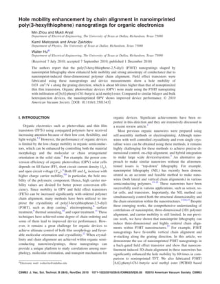
Figure 1 shows the schematic of the fabrication process of
nanograting FETs and OPV devices side by side. These two
fabrication processes share some steps, such as spin coating
and nanoimprinting of P3HT. Nanoimprinting creates poly-
mer chain alignment, which is favorable to both devices as
shown. FETs were fabricated using nanoimprinted P3HT
gratings as channels to measure the hole mobility in com-
parison to nonimprinted TFT. All FETs have top contacts
deposited by evaporation through a shadow mask and use a
back gate configuration. FETs were fabricated on heavily
doped n-type ͑100͒ Si wafer ͑0.002 ⍀ cm͒ substrates with
200 nm thick thermally grown silicon oxide as gate dielec-
tric. 200 nm thick Al was deposited by an electron-beam
evaporator on the backside of the Si substrates as a back gate
electrode. Regio-regular P3HT ͑Sigma-Aldrich, Mn
=25 000–35 000 Da͒ in dichlorobenzene was spin coated
on oxidized Si, followed by annealing at 150 °C for 5 min to
obtain ϳ80 nm thick P3HT films. P3HT nanogratings were
fabricated by nanoimprinting at 170 °C for 10 min at 50 bars
and demolded at 70 °C. As shown in Fig. 2͑a͒, the nanoim-
printed gratings covering 200 mm2
areas are about 150 nm
in height, 65 nm in width, and 200 nm in pitch, with 20 nm
thick residual layer. Cr/Au ͑20 nm/200 nm͒ pads as source
and drain contacts were deposited sequentially by electron-
beam evaporation and defined by a shadow mask with a
channel length of 30 m and channel widths of 100 m on
top of the P3HT nanogratings. The source/drain metal pads
have two different orientations, e.g., along the grating direc-
tion for parallel devices and perpendicular to the grating di-
rection for perpendicular devices ͓Fig. 2͑b͔͒. For perpendicu-
lar devices, the 20 nm thick residual layer connects the
nanogratings. A set of TFT devices were also fabricated us-
ing nonimprinted P3HT films with three different thicknesses
͑20, 80, and 140 nm͒ for comparison. Among these three
thicknesses of P3HT film, 20 and 80 nm are chosen to be
equal to the residual layer thickness and starting film thick-
ness of nanoimprinted FETs, respectively. Finally, the de-
vices were annealed at 100 °C for 6–8 h in nitrogen envi-
ronment to dedope oxygen before measurements.18
The
electrical characterizations were performed using a Cascade
Microtech probing station and a Keithley 4200 semiconduc-
tor characterization system at room temperature and ambient
condition.
Figure 1͑b͒ shows the fabrication process to make the
nanograting P3HT/PCBM OPV devices using imprinted
P3HT nanogratings on patterned indium tin oxide ͑ITO͒ ͑re-
sistance 15–30 ⍀/Luminescence Technology, Taiwan͒
coated glass. The device area ͑ϳ0.1 cm2
͒ was defined by the
FIG. 1. ͑Color online͒ Schematic of the fabrication process of ͑a͒ nanograting field effect transistor and ͑b͒ nanograting solar cells. The cartoon of polymer
chain orientation shows -stacking in the lateral direction and backbone orientation in the vertical direction in P3HT nanogratings.
FIG. 2. ͑Color online͒ ͑a͒ Schematic of the nanograting field effect transistor
with source and drain parallel and perpendicular to the nanogratings, and
thin film transistor; ͑b͒ SEM image of P3HT nanogratings. The grating has
20 nm residual layer and 150–170 nm grating height.
C6M64 Zhou et al.: Hole mobility enhancement by chain alignment C6M64
J. Vac. Sci. Technol. B, Vol. 28, No. 6, Nov/Dec 2010
3. intersection of ITO and Al cathodes. First, a PEDOT:PSS
layer or poly-3,4-ethylenedioxythiophene-polystyrene sul-
phonic acid ͑H. C. Starck, Inc.͒ mixed with d-sorbitol ͑Ald-
rich͒ was spin coated on the ITO substrates and dried in N2
at 180 °C for 20 min. Then, an 85 nm thick P3HT film was
spin casted on top of the PEDOT:PSS layer. Nanoimprinting
was performed using a Si mold ͑gratings of 100 nm width,
100 nm depth, and 200 nm pitch͒ to form nanograting struc-
tures using similar NIL conditions as described for FETs.
The resulting nanogratings have the same dimensions as the
mold and a 30 nm thick residual layer. PCBM of 0.8 wt %
in dichloromethane was spin casted as electron transfer ma-
terial onto the imprinted P3HT nanogratings. Figure 3͑b͒
shows scanning electron microscopy ͑SEM͒ images of P3HT
nanogratings before and after infiltration of PCBM. We
found that dichloromethane is an orthogonal solvent that dis-
solves PCBM well but not the P3HT, allowing the stacking
of PCBM on top of the P3HT layer without distortion of the
nanostructures.14,19
A thin LiF ͑3 nm͒ layer and 100 nm thick
aluminum were thermally evaporated on the PCBM coated
sample as the top electrode. The devices are characterized
after annealing at 120 °C for 3 min. As a control study, a
similar process was used to fabricate bilayer and blended
nonpatterned solar cells without the imprint process. Figure
3͑a͒ shows the schematic designs of bilayer, blended, and
nanoimprinted OPV devices. The bilayer devices contain a
50 nm PCBM layer on top of an 85 nm thick P3HT layer,
while the blend devices were made by spin coating an
ϳ135 nm thick film of P3HT/PCBM blend ͑1:0.9͒ on a sub-
strate. The devices were measured using Air Mass 1.5 global
filtered solar simulated light ͑AM 1.5͒ calibrated using a Na-
tional Renewable Energy Laboratory certified silicon diode
with a KG-5 color filter ͑Hamamatsu͒ at an intensity of
100 mW/cm2
.
III. RESULTS AND DISCUSSIONS
Figure 4 shows drain current versus drain voltage ͑Id-Vd͒
curves demonstrating typical FETs behavior with linear and
saturation regions. Field effective mobilities are extracted ac-
cording to
ץId
ץVg
=
FEWCiVd
L
, ͑1͒
where W, L, and Ci are the channel width, channel length,
and gate capacitance, respectively.20
In our devices, the chan-
nel length and width were 100 and 30 m, respectively. We
intend to use the linear low-voltage region to calculate hole
mobility, which is close to the biasing conditions of solar
cells. The operation of solar cells can never be in the satura-
tion or high-voltage region. From Fig. 4, the linear regions of
the Id-Vd curves stay below Vd=−10 V, thereby we fixed Vd
at Ϫ5 V during Id-Vg measurements. The mobility values
were extracted using Eq. ͑1͒, where the value of GM, i.e.,
ץId/ץVg was obtained from KEITHLY software.21
The calcu-
lated mobility values are shown in Tables I and II.
As expected, nanograting FETs show mobility values
͑3.04ϫ10−2
cm2
/V s͒ 60 times higher than that of the TFT
devices of 80 nm P3HT film ͑5.62ϫ10−4
cm2
/V s͒. The
TABLE I. Hole mobility extracted from I-V curves of back-gated FETs for nanograting parallel, perpendicular,
and thin film transistors, showing strong anisotropic conductivity in P3HT nanogratings.
Device Parallel Perpendicular Thin film
Mobility ͑cm2
/V s͒ 3.04ϫ10−2
Ϯ3ϫ10−3
5.48ϫ10−5
Ϯ5ϫ10−6
5.62ϫ10−4
Ϯ5ϫ10−5
FIG. 3. ͑Color online͒ ͑a͒ Schematics of bilayer, blend, and nanograting
solar cells; SEM images of P3HT nanogratings ͑b͒ before and ͑c͒ after
infiltration of PCBM.
FIG. 4. IDS vs VDS characteristics of nanograting FET and TFT with effective
channel length of 30 m, showing the accumulation mode operation when
gate biases were applied from Ϫ5 to Ϫ35 V with an interval of Ϫ5 V.
C6M65 Zhou et al.: Hole mobility enhancement by chain alignment C6M65
JVST B - Microelectronics and Nanometer Structures
4. P3HT thin film did not have any special treatment, such as
surface treatment8
and electrospinning;7
therefore, the crys-
tallinity of the film is low. The degree of crystallinity is
significantly proportional to mobility values,15
so the TFT
devices have much lower mobility compared to ordered nan-
ograting FETs. The measured results also show a highly an-
isotropic conductance behavior in nanogratings: mobility
along the grating direction is 3.04ϫ10−2
cm2
/V s, while
mobility perpendicular to the grating direction is 5.11
ϫ10−5
cm2
/V s. Moreover, mobility along the perpendicu-
lar direction is one order of magnitude lower than the thin
film. Table II shows the TFT mobility values for three dif-
ferent thicknesses ͑20, 80, and 140 nm͒, and as we can see,
the values are very close. It proves that the thin residual layer
in perpendicular devices was not the reason for the low value
of charge mobility of nanograting FETs in the perpendicular
direction. P3HT conducts holes by a hopping mechanism and
hopping rate decreases exponentially with increasing hop-
ping distance,16
hence mobility parallel to the grating is ex-
pected to be significantly higher than in the perpendicular
direction, as we observed experimentally. The mobility of
P3HT depends on a number of other factors, such as polymer
purity and high polydispersity, processing conditions, and
measurement conditions.22–25
With specific film optimization
and treatment, the reported mobility of P3HT can be as high
as ϳ0.1 cm2
/V s, which is higher than our results. How-
ever, they were measured under much higher drain voltage
and in the saturation region, while our mobility is measured
in the linear region under low voltages, which are the condi-
tions for solar cell applications.26
Hole mobility enhancement in P3HT nanogratings is due
to nanoconfinement induced chain alignment in P3HT nan-
ogratings defined by nanoimprint lithography, as shown in
our previous work.17
In this highly ordered 3D grating struc-
ture, hopping distances of - stacking in the parallel direc-
tion and along the vertically aligned polymer backbones are
about 3.8 Å, while a hopping distance over the side chains is
about 16.8 Å in the perpendicular direction.17
This nanocon-
finement induced ordering polymer chain is due to the com-
bined effect of polymer flow at nearly molten state during the
nanoimprinting and - interchain interaction and side chain
hydrophobic interactions with hydrophobic mold walls. It
has been shown that this directed organization goes up to
tens of nanometers ͑ϳ50 nm͒ for thin film P3HT contacting
a substrate.9
Since the P3HT is confined in the mold cavity
between two walls, this range would double. Such directed
organization is likely incomplete when the channel width
and/or the period of the nanograting mold is higher than the
range of 100 nm. The nanograting size also affects polymer
flow behavior to the nanochannels during nanoimprinting.
Therefore, such kind of chain alignment cannot be expected
when large feature size nanogratings are used. Previously,
Cui et al. used a 700 nm period grating mold with 50% duty
cycle to improve the hole mobility of P3HT by NIL. They
found a 12-fold increase in mobility from P3HT nanograt-
ings compared to thin film. They observed that the carrier
mobility in the perpendicular direction is two times that of
the parallel direction, which is contradictory to our results.15
Their results are more likely due to pressure-induced crystal-
lization for large period gratings rather than nanoconfine-
ment induced polymer chain alignment and polymer flow
behavior.27,28
As described earlier, P3HT nanogratings exhibit a highly
anisotropic conductance behavior: the mobility parallel to the
grating direction is about 600 times as much as the perpen-
dicular direction. This is due to highly ordered chain orien-
tation in the grating structure: - stacking in the parallel
direction with vertically aligned backbones.17
Since the hop-
ping distance along - stacking and along the backbone is
equal ͑3.8 Å͒, the mobility along the vertical direction
would be very close to the values parallel to the grating
direction. So the field effective mobility calculated for the
parallel direction can be a good estimate of the mobility in
the vertical direction, which is the hole transport direction in
solar cells. These results suggest that nanoimprinted solar
cells would have higher hole carrier mobility than bulk het-
erojunction solar cells. The high mobility enabled by the
favorable 3D chain configuration can contribute to the im-
proved Isc, FF, and efficiency of the nanoimprinted OPV so-
lar cells. To prove this, nanograting OPV devices were fab-
ricated and characterized.
I-V curves of bilayer, blended, and nanoimprinted OPV
devices are plotted in Fig. 5, showing our preliminary results
of using high density and ordered nanowires to make P3HT/
TABLE II. Hole mobility extracted from I-V curves of back-gated thin film transistors with different thicknesses,
showing no dependence of hole mobility on the film thickness.
Thickness 20 nm 80 nm 140 nm
Mobility ͑cm2
/V s͒ 4.67ϫ10−4
Ϯ9.43ϫ10−5
4.30ϫ10−4
Ϯ1.25ϫ10−4
5.24ϫ10−4
Ϯ1.73ϫ10−4
FIG. 5. I-V curves of bilayer, blend, and nanograting OPV devices.
C6M66 Zhou et al.: Hole mobility enhancement by chain alignment C6M66
J. Vac. Sci. Technol. B, Vol. 28, No. 6, Nov/Dec 2010
5. PCBM solar cells, and their device parameters are shown in
Table III. The efficiency of nanoimprinted OPV is higher
than bilayer and blend solar cells. Both FF and Isc are higher
in P3HT nanograting solar cells than the bilayer and blended
counterparts. There can be two factors for this improved per-
formance: increase in interface area and increase in charge
mobility. The interface area of blend solar cells is the high-
est, but its Isc is smaller than the nanograting devices, indi-
cating that the hole mobility is enhanced in nanograting solar
cells due to 3D chain alignment. On the other hand, the
polymer crystallinity of bilayer solar cells can be better than
in the nanostructures and blend devices, but it has the least
interface area. Therefore, we believe that the improved per-
formance in nanograting devices is partially due to the better
chain alignment in P3HT nanogratings because high carrier
mobility improves FF, external quantum efficiency, and
Isc.5,22,23
A significant increase in nanoimprinted solar cell
performance can be expected by increasing the density and
aspect ratio of nanogratings to increase the area of interface
in addition to the enhancement of charge carrier mobility.
IV. CONCLUSIONS
We have shown that nanoimprint lithography is an effec-
tive way to enhance the charge carrier mobility of P3HT in
field effect transistor and solar cells by inducing favorable
3D chain alignments in nanogratings. Nanoimprint also pro-
vides a precise nanostructuring method to shape heterojunc-
tions so as to decrease the exciton travel length for charge
dissociation, enhance charge transport and charge collection,
and improve power conversion efficiency in OPV. In addi-
tion, polymer chain orientation in lithographically defined
polymer nanogratings provides a unique platform to study
correlations between morphology and transport mechanism
for organic devices.
ACKNOWLEDGMENTS
This work is supported by the National Science Founda-
tion ͑Grant No. ECCS-0901759͒, Welch Foundation Grant
No. AT-1617, and CONTACT/AF consortium of Texas. M.Z.
would like to thank UT Dallas for the get-doc fellowship.
1
V. D. Mihailetchi, H. X. Xie, B. de Boer, L. M. Popescu, J. C. Hummelen,
P. W. M. Blom, and L. J. A. Koster, Appl. Phys. Lett. 89, 012107 ͑2006͒.
2
T. Aernouts, P. Vanlaeke, W. Geens, J. Poortmans, P. Heremans, S.
Borghs, R. Mertens, R. Andriessen, and L. Leenders, Thin Solid Films
451–452, 22 ͑2004͒.
3
A. L. Briseno, S. C. B. Mannsfeld, S. A. Jenekhe, Z. Bao, and Y. Xia,
Mater. Today 11, 38 ͑2008͒.
4
S. R. Forrest, MRS Bull. 30, 28 ͑2005͒.
5
S. E. Shaheen, C. J. Brabec, N. S. Sariciftci, F. Padinger, T. Fromherz,
and J. C. Hummelen, Appl. Phys. Lett. 78, 841 ͑2001͒.
6
A. Gadisa, F. L. Zhang, D. Sharma, M. Svensson, M. R. Andersson, and
O. Inganäs, Thin Solid Films 515, 3126 ͑2007͒.
7
J. Park, S. Lee, and H. H. Lee, Org. Electron. 7, 256 ͑2006͒.
8
S. Lee, G. D. Moon, and U. Jeong, J. Mater. Chem. 19, 743 ͑2009͒.
9
R. J. Kline, M. D. McGehee, and M. F. Toney, Nature Mater. 5, 222
͑2006͒.
10
D. E. Motaung, G. F. Malgas, C. J. Arendse, S. E. Mavundla, C. J.
Oliphant, and D. Knoesen, J. Mater. Sci. 44, 3192 ͑2009͒.
11
Y. Zhao, Z. Y. Xie, Y. Qu, Y. H. Geng, and L. X. Wang, Appl. Phys. Lett.
90, 043504 ͑2007͒.
12
I. Mcculloch, Nature Mater. 4, 583 ͑2005͒.
13
Z. J. Hu, G. Baralia, V. Bayot, J. F. Gohy, and A. M. Jonas, Nano Lett. 5,
1738 ͑2005͒.
14
M. Aryal, F. Buyukserin, K. Mielczarek, X.-M. Zhao, J. Gao, A. Zakhi-
dov, and W. Hu, J. Vac. Sci. Technol. B 26, 2562 ͑2008͒.
15
D. Cui, H. Li, H. Park, and X. Cheng, J. Vac. Sci. Technol. B 26, 2404
͑2008͒.
16
Z. J. Hu, B. Muls, L. Gence, D. A. Serban, J. Hofkens, S. Melinte, B.
Nysten, S. Demoustier-Champagne, and A. M. Jonas, Nano Lett. 7, 3639
͑2007͒.
17
M. Aryal, K. Trivedi, and W. Hu, ACS Nano 3, 3085 ͑2009͒.
18
H. P. Jia, G. K. Pant, E. K. Gross, R. M. Wallace, and B. E. Gnade, Org.
Electron. 7, 16 ͑2006͒.
19
A. L. Ayzner, C. J. Tassone, S. H. Tolbert, and B. J. Schwartz, J. Phys.
Chem. C 113, 20050 ͑2009͒.
20
E. von Hauff, V. Dyakonov, and R. Parisi, Sol. Energy Mater. Sol. Cells
87, 149 ͑2005͒.
21
H. Q. Liu, C. H. Reccius, and H. G. Craighead, Appl. Phys. Lett. 87,
253106 ͑2005͒.
22
R. J. Kline, M. D. McGehee, E. N. Kadnikova, J. S. Liu, J. M. J. Fréchet,
and M. F. Toney, Macromolecules 38, 3312 ͑2005͒.
23
J. A. Merlo and C. D. Frisbie, J. Phys. Chem. B 108, 19169 ͑2004͒.
24
M. L. Chabinyc, R. A. Street, and J. E. Northrup, Appl. Phys. Lett. 90,
123508 ͑2007͒.
25
K. Norrman, A. Ghanbari-Siahkali, and N. B. Larsen, Annu. Rep. Prog.
Chem., Sect. C: Phys. Chem. 101, 174 ͑2005͒.
26
Y. Fu, C. Lin, and F.-Y. Tsai, Org. Electron. 10, 883 ͑2009͒.
27
H. D. Rowland, W. P. King, J. B. Pethica, and G. L. W. Cross, Science
322, 720 ͑2008͒.
28
C. F. Shih, K. T. Hung, J. W. Wu, C. Y. Hsiao, and W. M. Li, Appl. Phys.
Lett. 94, 143505 ͑2009͒.
TABLE III. Device characteristics for bilayer, blend, and nanograting solar
cells, indicating improved power conversion efficiency by the nanograting
device morphology.
Devices Gratings Blend Bilayer
Voc ͑V͒ 0.55 0.56 0.46
Isc ͑mA/cm2
͒ 11.2 10.3 10.4
FF 0.45 0.43 0.41
͑%͒ 2.76 2.50 1.96
C6M67 Zhou et al.: Hole mobility enhancement by chain alignment C6M67
JVST B - Microelectronics and Nanometer Structures