SlideShare a Scribd company logo
1 of 1
Finite Element Analysis on Structure in Hyatt Collapse
Meng Lu1, Jiaying Gao1
Department of Mechanical Engineering
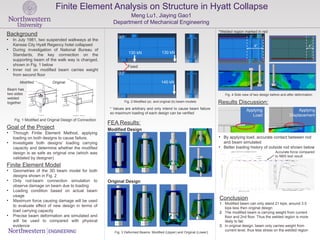
* Values are arbitrary and only intend to cause beam failure
so maximum loading of each design can be verified
Background
• In July 1981, two suspended walkways at the
Kansas City Hyatt Regency hotel collapsed
• During investigation of National Bureau of
Standards, the key connection on the
supporting beam of the walk way is changed,
shown in Fig. 1 below
• Inner rod on modified beam carries weight
from second floor
Finite Element Model
• Geometries of the 3D beam model for both
designs shown in Fig. 2
• Only rod-beam connection simulation to
observe damage on beam due to loading
• Loading condition based on actual beam
usage
• Maximum force causing damage will be used
to evaluate effect of new design in terms of
load carrying capacity
• Precise beam deformation are simulated and
will be used to compared with physical
evidence
Goal of the Project
• Through Finite Element Method, applying
loading on both designs to cause failure.
• Investigate both designs’ loading carrying
capacity and determine whether the modified
design is as safe as original one (which was
validated by designer)
Modified Original
Fig. 1 Modified and Original Design of Connection
Fig. 2 Modified (a) and original (b) beam models
(a)
(b)
Fixed
130 kN 130 kN
140 kN
FEA Results:
Applying
Load
Applying
Displacement
• By applying load, accurate contact between rod
and beam simulated
• Better loading history of outside rod shown below
Modified Design
Original Design
Fig. 3 Deformed Beams: Modified (Upper) and Original (Lower)
*Welded region marked in red
Fig. 4 Side view of two design before and after deformation
Accurate force compared
to NBS test result
Conclusion
1. Modified beam can only stand 21 kips, around 3.5
kips less then original design
2. The modified beam is carrying weight from current
floor and 2nd floor. Thus the welded region is more
likely to fail.
3. In original design, beam only carries weight from
current level, thus less stress on the welded region
Beam has
two sides
welded
together Results Discussion:
8” 4”

More Related Content

What's hot

Pavement skid resistance
Pavement skid resistancePavement skid resistance
Pavement skid resistance
Hai Vo
 
pavement analysis
pavement analysis pavement analysis
pavement analysis
Saeed Badeli
 

What's hot (20)

Design project
Design projectDesign project
Design project
 
Bridge construction-railway
Bridge construction-railwayBridge construction-railway
Bridge construction-railway
 
A Comperative study of Analysis of a G+3 Residential Building by the Equivale...
A Comperative study of Analysis of a G+3 Residential Building by the Equivale...A Comperative study of Analysis of a G+3 Residential Building by the Equivale...
A Comperative study of Analysis of a G+3 Residential Building by the Equivale...
 
Pavement design
Pavement designPavement design
Pavement design
 
IRJET- A Study of Cement Treated Base and Sub Base in Flexible Pavement
IRJET-  	  A Study of Cement Treated Base and Sub Base in Flexible PavementIRJET-  	  A Study of Cement Treated Base and Sub Base in Flexible Pavement
IRJET- A Study of Cement Treated Base and Sub Base in Flexible Pavement
 
Pavement skid resistance
Pavement skid resistancePavement skid resistance
Pavement skid resistance
 
Design of flexible pavements as per IRC37
Design of flexible pavements as per IRC37 Design of flexible pavements as per IRC37
Design of flexible pavements as per IRC37
 
G+3 APARTMENT BUILDING PROJECT REPORT
G+3 APARTMENT BUILDING  PROJECT  REPORTG+3 APARTMENT BUILDING  PROJECT  REPORT
G+3 APARTMENT BUILDING PROJECT REPORT
 
ANALYSIS & DESIGN OF G+3 STORIED REINFORCED CONCRETE BUILDING
ANALYSIS & DESIGN OF G+3 STORIED REINFORCED CONCRETE BUILDING ANALYSIS & DESIGN OF G+3 STORIED REINFORCED CONCRETE BUILDING
ANALYSIS & DESIGN OF G+3 STORIED REINFORCED CONCRETE BUILDING
 
Rigid pavement design
Rigid pavement designRigid pavement design
Rigid pavement design
 
Part-I: Seismic Analysis/Design of Multi-storied RC Buildings using STAAD.Pro...
Part-I: Seismic Analysis/Design of Multi-storied RC Buildings using STAAD.Pro...Part-I: Seismic Analysis/Design of Multi-storied RC Buildings using STAAD.Pro...
Part-I: Seismic Analysis/Design of Multi-storied RC Buildings using STAAD.Pro...
 
Modern Trends In Pavement Design
Modern Trends In Pavement DesignModern Trends In Pavement Design
Modern Trends In Pavement Design
 
Mechanical Response Analysis of Asphalt Pavement Structure
Mechanical Response Analysis of Asphalt Pavement StructureMechanical Response Analysis of Asphalt Pavement Structure
Mechanical Response Analysis of Asphalt Pavement Structure
 
Pavement thickness design
Pavement thickness designPavement thickness design
Pavement thickness design
 
Cyclic Load Test on Beam-Column Behavior of Portal Frame Strengthening by Mic...
Cyclic Load Test on Beam-Column Behavior of Portal Frame Strengthening by Mic...Cyclic Load Test on Beam-Column Behavior of Portal Frame Strengthening by Mic...
Cyclic Load Test on Beam-Column Behavior of Portal Frame Strengthening by Mic...
 
pavement analysis
pavement analysis pavement analysis
pavement analysis
 
Benkelman beam deflection studies
Benkelman beam deflection studiesBenkelman beam deflection studies
Benkelman beam deflection studies
 
Design of a rigid pavement (jpcp & crcp)
Design of a rigid pavement (jpcp & crcp)Design of a rigid pavement (jpcp & crcp)
Design of a rigid pavement (jpcp & crcp)
 
Introduction to Pavement Design Concepts
Introduction to Pavement Design ConceptsIntroduction to Pavement Design Concepts
Introduction to Pavement Design Concepts
 
Seismic Response of R.C Multi-storeyed Building Strengthened by Dual Column F...
Seismic Response of R.C Multi-storeyed Building Strengthened by Dual Column F...Seismic Response of R.C Multi-storeyed Building Strengthened by Dual Column F...
Seismic Response of R.C Multi-storeyed Building Strengthened by Dual Column F...
 

Similar to walkway collapse analysis

Stress ribbon bridges stiffened by arches or cables
Stress ribbon bridges stiffened by arches or cablesStress ribbon bridges stiffened by arches or cables
Stress ribbon bridges stiffened by arches or cables
Masum Majid
 

Similar to walkway collapse analysis (20)

Sub.ass.2
Sub.ass.2Sub.ass.2
Sub.ass.2
 
Auber_Steel fiber reinforcement concrete_Slab on ground-Design Note
Auber_Steel fiber reinforcement concrete_Slab on ground-Design NoteAuber_Steel fiber reinforcement concrete_Slab on ground-Design Note
Auber_Steel fiber reinforcement concrete_Slab on ground-Design Note
 
ADVANCED ANALYSIS OF SPACE STEEL FRAMES
ADVANCED ANALYSIS OF SPACE STEEL FRAMESADVANCED ANALYSIS OF SPACE STEEL FRAMES
ADVANCED ANALYSIS OF SPACE STEEL FRAMES
 
Effect of creep on composite steel concrete section
Effect of creep on composite steel concrete sectionEffect of creep on composite steel concrete section
Effect of creep on composite steel concrete section
 
Cable Stay Bridge construction at Bardhman using LARSA and LUSAS four dimensi...
Cable Stay Bridge construction at Bardhman using LARSA and LUSAS four dimensi...Cable Stay Bridge construction at Bardhman using LARSA and LUSAS four dimensi...
Cable Stay Bridge construction at Bardhman using LARSA and LUSAS four dimensi...
 
J013166067
J013166067J013166067
J013166067
 
Finite element analysis of innovative solutions of precast concrete beamcolum...
Finite element analysis of innovative solutions of precast concrete beamcolum...Finite element analysis of innovative solutions of precast concrete beamcolum...
Finite element analysis of innovative solutions of precast concrete beamcolum...
 
Earthquake considiration on pier design
Earthquake considiration on pier designEarthquake considiration on pier design
Earthquake considiration on pier design
 
Vol3no2 4
Vol3no2 4Vol3no2 4
Vol3no2 4
 
Lec11 Continuous Beams and One Way Slabs(1) (Reinforced Concrete Design I & P...
Lec11 Continuous Beams and One Way Slabs(1) (Reinforced Concrete Design I & P...Lec11 Continuous Beams and One Way Slabs(1) (Reinforced Concrete Design I & P...
Lec11 Continuous Beams and One Way Slabs(1) (Reinforced Concrete Design I & P...
 
IRJETI Comparison of RC Beam-Column Joint with GFRC Beam-Column Joint using S...
IRJETI Comparison of RC Beam-Column Joint with GFRC Beam-Column Joint using S...IRJETI Comparison of RC Beam-Column Joint with GFRC Beam-Column Joint using S...
IRJETI Comparison of RC Beam-Column Joint with GFRC Beam-Column Joint using S...
 
Reinforced concrete Course Assignments, 2022
Reinforced concrete Course Assignments, 2022Reinforced concrete Course Assignments, 2022
Reinforced concrete Course Assignments, 2022
 
COMPOSITE BEAMS.pdf
COMPOSITE BEAMS.pdfCOMPOSITE BEAMS.pdf
COMPOSITE BEAMS.pdf
 
Advanced Plain concrete lecture 1.ppt
Advanced Plain concrete lecture 1.pptAdvanced Plain concrete lecture 1.ppt
Advanced Plain concrete lecture 1.ppt
 
Design of rectangular beam by USD
Design of rectangular beam by USDDesign of rectangular beam by USD
Design of rectangular beam by USD
 
Presentation
PresentationPresentation
Presentation
 
Progressive Collapse Analysis of RC Buildings with consideration of Effect of...
Progressive Collapse Analysis of RC Buildings with consideration of Effect of...Progressive Collapse Analysis of RC Buildings with consideration of Effect of...
Progressive Collapse Analysis of RC Buildings with consideration of Effect of...
 
Stress ribbon bridges stiffened by arches or cables
Stress ribbon bridges stiffened by arches or cablesStress ribbon bridges stiffened by arches or cables
Stress ribbon bridges stiffened by arches or cables
 
Reinforced concrete Course Assignments, 2023
Reinforced concrete Course Assignments, 2023Reinforced concrete Course Assignments, 2023
Reinforced concrete Course Assignments, 2023
 
IRJET- Flexural Strength of Reinforced Concrete Beam with Hollow Core at Vari...
IRJET- Flexural Strength of Reinforced Concrete Beam with Hollow Core at Vari...IRJET- Flexural Strength of Reinforced Concrete Beam with Hollow Core at Vari...
IRJET- Flexural Strength of Reinforced Concrete Beam with Hollow Core at Vari...
 

walkway collapse analysis

  • 1. Finite Element Analysis on Structure in Hyatt Collapse Meng Lu1, Jiaying Gao1 Department of Mechanical Engineering * Values are arbitrary and only intend to cause beam failure so maximum loading of each design can be verified Background • In July 1981, two suspended walkways at the Kansas City Hyatt Regency hotel collapsed • During investigation of National Bureau of Standards, the key connection on the supporting beam of the walk way is changed, shown in Fig. 1 below • Inner rod on modified beam carries weight from second floor Finite Element Model • Geometries of the 3D beam model for both designs shown in Fig. 2 • Only rod-beam connection simulation to observe damage on beam due to loading • Loading condition based on actual beam usage • Maximum force causing damage will be used to evaluate effect of new design in terms of load carrying capacity • Precise beam deformation are simulated and will be used to compared with physical evidence Goal of the Project • Through Finite Element Method, applying loading on both designs to cause failure. • Investigate both designs’ loading carrying capacity and determine whether the modified design is as safe as original one (which was validated by designer) Modified Original Fig. 1 Modified and Original Design of Connection Fig. 2 Modified (a) and original (b) beam models (a) (b) Fixed 130 kN 130 kN 140 kN FEA Results: Applying Load Applying Displacement • By applying load, accurate contact between rod and beam simulated • Better loading history of outside rod shown below Modified Design Original Design Fig. 3 Deformed Beams: Modified (Upper) and Original (Lower) *Welded region marked in red Fig. 4 Side view of two design before and after deformation Accurate force compared to NBS test result Conclusion 1. Modified beam can only stand 21 kips, around 3.5 kips less then original design 2. The modified beam is carrying weight from current floor and 2nd floor. Thus the welded region is more likely to fail. 3. In original design, beam only carries weight from current level, thus less stress on the welded region Beam has two sides welded together Results Discussion: 8” 4”

Editor's Notes

  1. <number>