
Recommended
Recommended
More Related Content
What's hot
What's hot (20)
Similar to Design and Additive Manufacturing Considerations for Liquid Rocket Engine Development
Similar to Design and Additive Manufacturing Considerations for Liquid Rocket Engine Development (20)
Recently uploaded
Recently uploaded (20)
Design and Additive Manufacturing Considerations for Liquid Rocket Engine Development
- 1. 1 Design and Additive Manufacturing Considerations for Liquid Rocket Engine Development Nihar Patel1 , Sean Standbridge2 , Martin Van Den Berghe3 , and Venkata Devalaraju4 University of Southern California, Los Angeles, CA, 90089, USA The effective use of additive manufacturing requires careful design methods, specifically targeting subsequent post-processing and machining efforts. This paper covers the design, manufacturing and post-processing considerations that went into the development of an additively manufactured, bi-propellant, pressure-fed liquid rocket engine. Special considerations include initial constraints on engine design related to DMLS printing requirements, as well as post-printing ultrasonic cleaning, heat treatment, wire EDM and machining processes. Unexpected design related challenges and complications were found and solved throughout the manufacturing process. Solutions, such as developing custom machining tools, were devised to overcome these difficulties and ultimately allowed the completion of a hot-fire readiness testing campaign. This project was designed and completed by the student- led Liquid Propulsion Laboratory at the University of Southern California. I. Nomenclature AM = Additive Manufacturing CAD = Computer Aided Design CAM = Center for Advanced Manufacturing CEA = Chemical Equilibrium with Applications CFD = Computational Fluid Dynamics DMLS = Direct Metal Laser Sintering EDM = Electric Discharge Machining FEA = Finite Element Analysis HIP = Hot Isostatic Pressing Isp = Specific impulse L* = Characteristic length LOX = Liquid Oxygen LPL = Liquid Propulsion Laboratory O/F ratio = Oxidizer/Fuel ratio PT = Pressure Transducer TC = Thermocouple USC = University of Southern California WIRES#13 = Winged Reusable Sounding Rocket #13 Note: All authors contributed equally to this publication 1 Master’s student, Dept. of Aerospace & Mechanical Engineering, student AIAA member. 2 Master’s student, Dept. of Aerospace & Mechanical Engineering, student AIAA member. 3 Ph.D. candidate, Dept. of Earth Sciences. 4 Master’s student, Dept. of Astronautical Engineering. Downloadedby92.129.167.138onAugust17,2019|http://arc.aiaa.org|DOI:10.2514/6.2019-4392 AIAA Propulsion and Energy 2019 Forum 19-22 August 2019, Indianapolis, IN 10.2514/6.2019-4392 Copyright © 2019 by the American Institute of Aeronautics and Astronautics, Inc. All rights reserved. AIAA Propulsion and Energy Forum
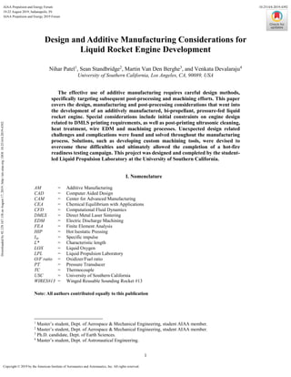
- 2. 2 II. Background and Motivation As a collaborative project between student-led University groups, the Liquid Propulsion Laboratory (LPL) of the University of Southern California (USC) developed Balerion (Fig. 1), a liquid fueled, bi-propellant rocket engine designed to serve as the propulsion system for the Winged Reusable Sounding Rocket #13 (WIRES#13), currently under development at the Kyushu Institute of Technology in Japan by the Kyutech Space Club. Propulsion system requirements for WIRES#13 include reusability, a total thrust of 20 kN, and a burn time of 25 seconds. In consideration, Balerion is designed to have 10 kN of thrust to be used on WIRES#13 in a dual engine configuration, using kerosene (Jet-A) and liquid oxygen (LOX) as propellants. Balerion’s performance parameters include a chamber pressure of 2.58 MPa (375 psi), an oxidizer/fuel (O/F) ratio of 1.5, a specific impulse of 241 seconds, and a total mass flow rate of 4.25 kg/s. The dual Balerion configuration is designed to lift the approximately 1-ton WIRES#13 vehicle to a maximum altitude of 6,100 m (20,000 ft). above sea level. A gliding descent and recovery would allow engine and vehicle refurbishment and reuse. The following sections detail the design and manufacturing process associated with the development-stage, additively manufactured Balerion engine. Further details on Balerion engine sizing and design process available in Ref. (Fessl, et al., 2018). Fig. 1 CAD model of the WIRES#13 vehicle (left), and photo the Balerion engine (right). III. Method of Manufacturing Additive manufacturing (AM) was chosen as it offers greater freedom, speed and complexity in design than traditional manufacturing methods, especially regarding integrated interior cavities. Additive Manufacturing Traditional manufacturing methods use subtractive processes to remove material until the final part specifications are reached. This requires designing components in such way that a machining tool could fully access all working surface areas, or, if cast, in a way that the component could be removed from a mold. Lacking these constraints, additive manufacturing allows unparalleled design freedom and complexity when compared to traditional subtractive manufacturing processes. Not only are more complex parts possible but AM can reduce part count and the time necessary to manufacture aerospace-grade quality parts. Since LPL is mainly comprised of graduate students in a 2- year degree program, rapid manufacturing and prototyping was a high priority requirement. Layer by layer manufacturing also allows critical features to be directly modeled into the design as opposed to traditional methods, which typically require multiple machining parts. This reduced part count not only increases reliability through a reduction of possible failure points, but also decreases the amount of machining required and ultimately reduces machining complexity, effort, and manufacturing costs. There are many different types of additive manufacturing, each with unique strengths and limitations. Powder bed fusion using direct metal laser sintering (DMLS) was chosen due to its availability and ability to create internal Downloadedby92.129.167.138onAugust17,2019|http://arc.aiaa.org|DOI:10.2514/6.2019-4392
- 3. 3 channels and holes. The Center for Advance Manufacturing (CAM), located on the campus of USC, possesses an EOS M 290 powder bed fusion additive manufacturing system, which “allows for fast, flexible and cost-effective production of metal parts directly from CAD data” (EOS GmbH Electro Optical Systems, 2019). The EOS M 290 The process for power bed fusion starts with a layer of powdered material spread evenly onto the build plate in a very thin layer. This build plate is isolated from contamination using a pressure and temperature-controlled nitrogen or argon sealed atmosphere. Next, a laser selectively sinters and solidifies a cross-section of powder, creating a melt pool and fusing it to the layer below. The platform is then lowered, and another powder layer is added and sintered. This process repeats itself until the part is finally completed and the excess powder is removed (Karimi, 2016). A graphic from EOS illustrates the process below: Fig. 2 Powder Bed Fusion Manufacturing Process 5 The EOS M 290 and specifically, powder bed fusion, have several constraints that limit design. The size of any printed part is constrained by the total working volume of the EOS M 290 build plate, the dimensions of which are 250 mm x 250 mm x 325 mm (9.85 in x 9.85 in x 12.8 in) (EOS GmbH Electro Optical Systems, 2019). This constraint limits the maximum size of additively manufactured parts and drove the decision to split the Balerion engine into two main parts, covered in more details in the sections to follow. For Inconel 718, the EOS M 290 has a minimum wall thickness of 0.2 to 0.4 mm (0.012 to 0.016 in) and a small part accuracy of ± 40 to 60 µm (± 1.6 to 2.4 x 10⁻³ in) depending on the settings used (EOS GmbH - Electro Optical Systems, 2018). This limitation drove minimum wall thickness and rib thickness values in the design, however, a factor of safety of more than one was used. Fabrication Constraints and Defects The constraint that needs the most attention is the overhang and associated inclined angle, which is the measured angle between the horizontal plane and the surface of the print. Overhang and excessively low inclined angles are to be avoided, as they will lead to fabrication defects and possible print failure (Wang, Yang, Yi, & Su, 2013). Inclined angle is illustrated in Fig. 3 below. 5 Graphic found on EOS Additive Manufacturing Benefits and Functional Principle Webpage URL: https://www.eos.info/additive_manufacturing/for_technology_interested All Rights Reserved. Downloadedby92.129.167.138onAugust17,2019|http://arc.aiaa.org|DOI:10.2514/6.2019-4392
- 4. 4 Fig. 3 Illustration of inclined angle and individual layer unsupported overhangs in reference to preceding layers When the inclined angle is above the minimum inclined, or critical angle, the print is in theory self-supporting and is likely to print without major defects. As shown in Fig. 3, each layer has an overhang in reference to the layer below it, dependent on the inclined angle and the constant layer thickness. As inclined angle decreases, unsupported overhang length increases. A critical angle of 45° has been proposed as a “reliable building angle” to ensure defect free fabrication (Wang, Yang, Yi, & Su, 2013). This critical angle was used for all Balerion part designs. In the DMLS additive manufacturing process for unsupported overhangs, the main fabrication defects are dross formation and warping that can eventually lead to layer separation and print failure. An experimental image of dross formation can be found in Ref. (Wang, Yang, Yi, & Su, 2013, p. 1476). Dross forms in overhang areas that are only supported by nonmelted powder instead of previously melted layers. This nonmelted support powder has “1/100th of the [heat conduction rate] of the solid supported zone” (Wang, Yang, Yi, & Su, 2013). This results in much more energy input into the nonmelted powder supported zone, a larger melt pool of powder, and possible molten powder dripping due to gravity and capillary force (Wang, Yang, Yi, & Su, 2013). Plastic deformation warping defects can occur when thermal stress, due to rapid melt pool solidification, exceeds the strength of the material. This can also occur in overhanging surfaces due to lack of solid surface support bonding with the previous layer (Wang, Yang, Yi, & Su, 2013). Warping will influence the following layers, potentially leading to a lack of powder, repeated laser scans, collisions with the powder scraper, and component breakage. Dross formation and warping can be minimized using reduced laser deposition energy, higher scanning speed, support material addition, and a higher inclined angle (Wang, Yang, Yi, & Su, 2013). Inversely, having an inclined angle below the critical angle value will lead to increased warping and dross formation. To reduce unsupported overhangs and associated dross formation, interior cavities and channels can be tear drop or diamond shaped, depending on the print direction. Small amounts of dross formation can manifest itself as increased surface roughness or surface defects. Due to these constraints, Balerion part print directions were considered and optimized during the design phase. Other common possible fabrication defects in DMLS include unique non-uniform precipitate microstructure phases. This can lead to unintended residual stresses not seen in traditional casting methods (Karimi, 2016). This is due to the rapid cooling of the molten material of the DMLS method when compared to casting. To eliminate these residual stresses, post-printing heat treatment is necessary. Excess porosity can also occur in laser sintering Downloadedby92.129.167.138onAugust17,2019|http://arc.aiaa.org|DOI:10.2514/6.2019-4392
- 5. 5 manufacturing. In porosity based defects, there are two types of pore formation, the “round shaped pore”, likely due to trapped gas bubbles and the “irregular shape pore,” due to lack of powder fusion caused by unstable molten pool shape (Karimi, 2016). This porosity, possibly a side effect of excessive scan speed or non-melted powder, leads to stress concentrations and points of weakness. Fine size gas-atomized powder, high laser deposition energy, and hot isostatic pressing can be used to decrease porosity (Karimi, 2016). The last major fabrication defect is a phenomenon known as balling. Due to surface tension and insufficient molten powder bonding with the preceding layers, the molten layer forms spheroidal beads. These beads lead to non-uniform printing and, if thicker than powder bed height, can jam the powder coating mechanism. Balling can be reduced by using very low oxygen levels and repeat laser exposure (Yap, et al., 2015). To avoid this defect, the EOS M 290 operates in either a pure argon or nitrogen atmosphere. Fabrication defects lead to unintended residual stresses in the part, largely in the direction normal to the laser scanning plane. These defects and internal stresses lead to cracking along grain boundaries and delamination between layers (Karimi, 2016). To avoid these fabrication defects several strategies are employed. The first is controlled scanning strategies and parameters, such as “sectorial scanning,” and custom printer setting optimization for points of complex geometry and points prone to failure. Preheating of the powder before melting and post-fabrication heat treatment can also reduce residual stress and fabrication defects (Yap, et al., 2015). Unfortunately, residual stress defects often do not manifest until well into the testing campaign or under near maximum loading conditions. DMLS defects can lead to a part having differing mechanical properties than a part created using casting or wrought methods. However, several studies have shown that with near 100% relative density, the ultimate yield strength for a DMLS test coupon is higher than the yield strength of a cast test coupon (Yap, et al., 2015). To reduce warping and dross formation in unsupported sections, sacrificial supports can be added to the design. These supports, whether removable with machining or permanent, strengthen the part and prevent distortion in unsupported zones. Supports can also be used as sacrificial material to raise the part from the build plate for removal. For secondary machining, such as threading and tapping, additional sacrificial material must be included. Removable solid supports can also be used as an integrated test coupon to confirm print quality and must be designed for easy removal. Cellular lattice structure supports can be used as permanent overhang support options that reduce weight and powder requirements. Due to the large nature of the Balerion engine parts, sacrificial support structures were used. Material Choice Material choice was constrained by the metals available for powder bed fusion, a full list of which can be found in Ref. (EOS GmbH Electro Optical Systems, 2019), and the minimum material properties necessary for rocket engine design, such as thermal conductivity necessary for cooling performance and high yield stress to ensure structural integrity. Using these constraints, two families of materials were considered, aluminum alloys for their high thermal conductivity and the high-strength nickel based super-alloy Inconel. Comparing material properties, AlSi10Mg and Inconel 718 were selected for further study and a comparison of their physical properties can be found in Ref. (Fessl, et al., 2018, p. 2). The high thermal conductivity of AlSi10Mg and relative ease of machining, when compared to Inconel, made AlSi10Mg an attractive option, but it did not have the necessary yield stress to withstand the operation pressures. Therefore, Inconel 718 was chosen. To meet required operating parameters, Inconel 718 parts were heat treated according to AMS 5662 standards. The post AMS 5662 physical properties of Inconel 718 can be found in Ref. (Fessl, et al., 2018, p. 2). IV. Key Design Features The aspect of engine design encompasses knowledge from many different engineering fields such as fluid dynamics, heat transfer, manufacturing, material science, etc. Each subject requires a level of competency to achieve optimal design results and instilling this competency in each member is the foundation on which the LPL was built upon (Targonski, Moruzzi, Fessl, Prochnicki, & Perry, 2018).The Balerion engine was the LPL’s first attempt to develop an additively manufactured engine and it came with a difficult learning curve. The following subsections dive into a simple background design overview, and for more detailed information, refer to Ref. (Fessl, et al., 2018) Downloadedby92.129.167.138onAugust17,2019|http://arc.aiaa.org|DOI:10.2514/6.2019-4392
- 6. 6 Initial Engine Sizing Table 1 Optimal engine parameters (Fessl, et al., 2018) Propellants LOX/Kerosene Chamber Pressure 2.59 MPa (375 psi) O/F ratio 1.5 Chamber Temperature 2464 K Thrust 10 kN Specific Impulse 241 s Total Mass Flow Rate 4.25 kg/s (9.37 lb/s) Once the key engine parameters were set (Table 1), it became apparent through initial sizing that an engine greater than the overall height of the printer build volume was needed. This led to the major decision to split the nozzle and chamber into two pieces and connect them via a flange. The specific dimensions for the split were driven by the EOS M 290 machine. Fig. 4 is a reference isometric view of the Balerion engine. Fig. 4 Isometric view of the Balerion Engine calling out major components Downloadedby92.129.167.138onAugust17,2019|http://arc.aiaa.org|DOI:10.2514/6.2019-4392
- 7. 7 Cooling System The nozzle was designed as an 80% bell-shaped nozzle, with an expansion ratio of 4.06, providing a sea level pressure (0 psig) optimized exit surface area. As this is a development engine, it will never see flight and was designed to be tested on static pads at or near sea level. As seen in Fig. 5, the nozzle, more specifically the fuel inlet, is the starting point for the fuel delivered from the feed system and the opening to the regenerative channels, the primary method of cooling used on the engine. The fuel enters the nozzle’s constant velocity manifold via a removable fuel inlet component. This fuel inlet was designed in order to avoid the need for machining directly into the nozzle, near the constant velocity manifold, a process that had the potential to create small metal shards that could clog the regenerative channels. The constant velocity manifold is a flow distribution system that takes the injected fuel and equalizes it circumferentially prior to it entering the regenerative cooling channels which travel axially throughout the entire engine. This manifold helps to maintain even pressure, and thus uniform mass flow, across all cooling channels (as well as film cooling outlets, which tap into cooling channels) in order to maximize the effectiveness of the cooling systems. Fig. 5 Cross-sectional view of the Balerion engine, displaying the propellant flow through the engine into the pintle injector For the fuel to travel all the way through the engine and into the injector, it is required to go through a transfer point between the nozzle and chamber flange. Doing so required the flange structure to effectively link internal regenerative cooling channels, while maintaining a leak-free seal that can withstand the thermal and mechanical stresses of a hot fire. This flange was designed with a small manifold cavity that allows unimpeded coolant transfer through it. To maintain a leak-free seal, the regenerative cooling cavity required heat resistant O-rings, seated in grooves straddling both sides of the flange cavity. Two inconel-718 O-rings were chosen as sealants for their thermal properties, matching the material of the engine. A circuitous, curved geometry design was chosen for the flange manifold around the internal O-ring groove to minimize the engine hot wall thickness and maximize heat transfer to the coolant even as the cooling channels divert away from the hot wall across the flange ( Fig. 6). This design, by removing internal ribs at the mating plane, eliminated the risk of channel misalignment during assembly, which would otherwise affect the coolant pressure regime and fuel mass flow rate. To further minimize the effects of misalignment of the nozzle and chamber, small 0.381 mm (0.015”, based off tolerance stack-ups) chamfers were added to the edges of the flange cavity openings on both nozzle and chamber. These chamfers reduced the restriction of the flow of the coolant in the unfortunate case of a misalignment ( Fig. 6). However, the primary method Downloadedby92.129.167.138onAugust17,2019|http://arc.aiaa.org|DOI:10.2514/6.2019-4392
- 8. 8 of avoiding misalignment involved using high precision dowel pins to lock in the two parts before being bolted down. More information regarding the assembly procedures can be found in Section VII, Subsection B Engine Assembly. Fig. 6 Close-up cross-sectional view of the engine flange, displaying the regenerative cooling channel manifold between the nozzle and chamber. Also showcases the distance of the film cooling holes to the flange. The cooling channels themselves were designed to the limitations of Inconel 718 DMLS additive manufacturing, particularly the allowable minimum wall thickness, while attempting to maximize the effective heat transfer across the material with a known thermal conductivity. To maximize cooling, 150 cooling channels were chosen as the optimal number to efficiently cool the engine, each with a constant rib thickness (in between channels) of 0.6 mm (0.024”), a wall thickness (hot wall to coolant) of 0.6 mm, and a channel depth of 1 mm (0.039”). These dimensional constraints implied a narrowing channel width (down to 0.63 mm at the throat from a maximum of 2.9 mm), a deliberate choice to increase coolant velocity at the throat, which is known to be the most thermally and structurally vulnerable component of any engine. However, even with this design consideration, computational fluid dynamics (CFD) predicted that the steady state nozzle wall temperatures would still climb up to 1400 K, which was near the 1650 K melting point of heat-treated Inconel 718. More importantly, finite element analysis (FEA) of the stress regime on the engine structures associated with nominal hot fire conditions (both pressure and thermal stresses) showed that the throat exceeded the yield stress of Inconel 718 (10 MPa, 1450 psia at 922 K), with the bulk of the stress modeled to be caused by thermal stress. For these reasons, the addition of a film cooling component was deemed critical to the structural integrity of the engine. For each regenerative cooling channel, a 0.38 mm (0.015”) film cooling orifice was designed to spray coolant (fuel) across the engine hot wall by taping off directly from the coolant flowing within the regenerative channels. The film cooling orifices had a steep 5° downwards angle and a variable, thinning geometry (circular to narrow rectangular) while maintaining constant hydraulic diameter to promote an even film flow from the outlet of the orifices. The actual location of the film cooling holes was a design decision that was intertwined with the flange that is seen in Fig. 6. With the flange being an unpredictable zone for thermal activity, it was deemed best to treat it as a critical failure point like the throat. To compensate, the film cooling orifices were placed slightly above the flange connection to thereby have the film cooling affect not only the throat but the flange as an added safety measure to the engine during operation. This can also be seen in Fig. 6. Injector A pintle-type injector (as seen in Fig. 5) was chosen as it is a design that promotes combustion stability (Heister, 2011), and drastically simplifies manufacturing steps. The Balerion injector system is composed of a detachable center annulus (pintle mount) and pintle for the LOX flow, and relies on a manifold within the engine chamber that surrounds the pintle to collect and direct the regenerative coolant (fuel) into the combustion chamber ( Fig. 5). The pintle is Downloadedby92.129.167.138onAugust17,2019|http://arc.aiaa.org|DOI:10.2514/6.2019-4392
- 9. 9 mounted into the center annulus via a cryo-sealed thread. This design is a modular in the sense that it allows for testing versatility with various pintle designs. The designs for these components have been significantly simplified for printing and machining to keep the cost low to allow for quick iterations based on empirical testing results. The pintle was designed with an internal concave conical feature near the LOX outflow channels in order to ensure a safe pressure drop (typically 20% of chamber pressure) over the pintle for combustion stability, as well as a hexagonal concavity at the bottom tip to easily torque the pintle onto the center annulus. These features required no post-print work. Ignition System The method of ignition for the Balerion engine involves a pyro system that was integrated inside the combustion chamber. This pyro ignitor, lit using an e-match, made use of a solid rocket booster (SRB) commonly found on model rockets as the source of heat that will combust the propellants once inside the combustion chamber. A pyro-based ignitor was chosen for its ease of design and widely available resources for support information. The pyro ignitor, as seen in Fig. 7, was mounted on a trident-shaped bracket that was printed out of ABS plastic to hold it inside the chamber prior to propellant flow. The bracket itself was mounted using threaded rods and connected onto the end threads of two engine flange bolts. The plastic bracket and the threaded rods were held together using shear pins that have been specifically selected to break once combustion occurs. However, careful consideration had been taken to ensure that the ignitor mount did not shear during cold flow testing. As an additional safety measure during the engine hot fire, the ignition system would simply be melted away by the flame in the case where the shear pins fail to break. Fig. 7 View of the SRB pyro ignition system mounted on the Balerion engine on the left and mounted on a plastic print model on the right. Downloadedby92.129.167.138onAugust17,2019|http://arc.aiaa.org|DOI:10.2514/6.2019-4392
- 10. 10 V. Printing Considerations Most of the printing considerations were focused around specific areas of the engine. These include the injector fuel annulus (since it is a part of the combustion chamber), the chamber/nozzle flange, the sensor ports, the nozzle converging/diverging geometry, and the constant velocity manifold. The CAD model for each component was also altered from the final version to remove machined features such as threads, bolt holes, O-ring grooves, etc. The following covers the printing aspects taken into considerations for each of the previously listed areas. The print direction was one of the most important decisions made during the initial design phase as it controlled everything relating to the geometry of each component. For all components, 2 mm (0.070”) of support material was added to the print foundation to allow for enough room to easily cut the part off the build plate upon completion. The USC Center of Advanced Manufacturing recommended at least 1 mm for safe part removal, but to provide an extra factor of safety against various build plate removal methods, 2 mm was chosen as an optimal value. To find out more about the build plate removal methods used on the Balerion engine, refer to Section VI Subsection C Build Plate Removal. Additionally, for all parts, text engraving was used for not only organizing the nomenclature of all sensor ports and their measuring purposes (pressure, temperature, etc.), but also to mark alignment features for added reliability during engine assembly. Reference Section VII, Subsection B Engine Assembly for more on the assembly aspects. Specifics about each component is broken up in the sub-sections below. Chamber Fig. 8 Printed CAD Model of Combustion Chamber The chamber was printed in flange up direction, as seen in Fig. 8, due to two primary reasons. One was to avoid having the internal geometry of the chamber need any support material as that would be difficult to remove and the other was the design of the injector. The fuel annulus was pre-designed into the chamber and serves as the transfer point for the fuel traveling up the regenerative channels to go into the combustion chamber to mix with the oxidizer and be ignited. Since the fuel travels from the constant velocity manifold through 150 separate channels, it needs to be re-combined into a centralized manifold before being injected into the chamber to ensure an equalized sheet of fuel is hitting the oxidizer for optimal combustion. In Fig. 9, a section view of the printed chamber CAD model (dark grey representing the printed body of the chamber) showcases the fuel annulus. It was designed to be at the inclined angle of 45° to avoid the need of any extra support material. With the pintle and center annulus assembly installed inside the chamber, the fuel annulus leaves a 0.61 mm (0.024”) gap between the outer diameter of the pintle and inner diameter of fuel annulus rib. This is where the sheet of fuel that is injected into the chamber is formed. For more information regarding how the injector works can be found previously within Section IV, Subsection C Injector. Downloadedby92.129.167.138onAugust17,2019|http://arc.aiaa.org|DOI:10.2514/6.2019-4392
- 11. 11 Fig. 9 Section cut of printed CAD model of combustion chamber, showcasing the internal fuel annulus design to avoid support material. Due to this selected print direction, the flange had to be adjusted to certify proper printing. For the flange, a solid 45° support structure was added, it can be seen in Fig. 9. This added a large amount of weight to the build plate and caused unforeseen concerns that will be covered later within the lessons learned, Section VIII, Subsection E Warping and Support Structures. This added structure was used to support the weight of the flange during the printing process to safeguard the layers from detaching from one another and ultimately causing the entire part to fail. Similarly, the internal structure of the regenerative channels also required supports to handle the weight of the flange. Therefore, within each channel, pyramid structures (Fig. 10) were added. Fig. 10 Partial section cut of printed CAD model of chamber to showcase designed support structure in between the 150 regenerative channels. To prevent having to remove additional support material, the 4 sensor ports that surround the chamber outer diameter were designed at 45° respective to the build direction with prebuild pilot holes that lead directly into the chamber to measure chamber pressure. These pilot holes (0.8 mm, 0.032” in diameter) go directly through 4 ribs with slightly expanded regions to allow for an increased factor of safety. Their impact on cooling performance however Downloadedby92.129.167.138onAugust17,2019|http://arc.aiaa.org|DOI:10.2514/6.2019-4392
- 12. 12 was deemed to be negligible. Additionally, 3 more sensor pilot holes have been placed at the bottom of the chamber when viewing in respect to the print direction to measure both pressure and temperature of the fluid prior to the injector. These pilot holes were circular since small overhangs can be printed. However, to allow for a probe thermocouple (TC) to be placed inside one of the sensor ports, the holes were slightly expanded (1.98 mm, 0.078” in diameter) to allow for a sliding fit. MS-Boss fittings were used for all the sensor ports, as they came prebuilt with an O-ring groove for sealing. Meaning that even if fluid were to backflow through the chamber it would be unable to escape into the ambient environment. Reference Fig. 11 for images of the sensor ports. Fig. 11 Section cut of printed CAD model of combustion chamber, showcasing the sensor port locations with pilot holes built in. Finally, the last key feature that had to be adjusted for printing on the chamber was the 150 film cooling holes that tap into each of the regenerative channels and cut across the engine’s inner chamber wall. Their location on the engine was strictly driven by the placement of the flange as that was the most unpredictable region in terms of cooling requirements. These orifices were printed at a 5° offset from axial as that was determined to allow the fluid to spread thoroughly across the chamber wall covering both the flange and nozzle throat. For more information regarding the cooling system design, refer Section IV, Subsection B Cooling Systems. Due to the diameter of the orifices (0.38 mm, 0.015”) being near the printing limitations, a custom shape was applied to the model to increase its reliability throughout the print. It was done by taking an oval shape from inside the channel wall and sweeping it to a trapezoidal shape that was placed on the inner diameter of the chamber. This trapezoidal shape was designed to expand the traveling fluid to spray in a wider spread and thus cover more area within the combustion chamber per orifice for more efficient cooling. In Fig. 12 below, the diameter of the orifice remains constant as that dictates the delivered mass flow of fuel being injected while the inlet and outlet shapes vary to allow for optimal printing. The film cooling orifices are one of the most critical features of the engine, as they are the thermal control for the most critical locations (flange and throat) and without them the engine performance would drastically suffer. Therefore, since typical circular orifices have a potential for overhangs near the converging section, this custom solution was implemented as a means of avoiding clogged orifices. However, even with the planning that was put in place to avoid clogging, an unexpected problem was still found during initial testing and is covered more later in the paper. Downloadedby92.129.167.138onAugust17,2019|http://arc.aiaa.org|DOI:10.2514/6.2019-4392
- 13. 13 Fig. 12 Section cut of printed CAD model of combustion chamber, showcasing the unique shape of the film cooling orifices designed for more reliable printing in the set direction. Nozzle Fig. 13 Printed CAD Model of Nozzle The nozzle in terms of print considerations was a lot less concerning since it was open on both ends. Primarily, this meant that the flange could be printed downward as demonstrated in Fig. 13. This drastically reduced the need for the heavy support material that was placed onto the chamber, and thus reduced the overall cost to print the part since less material was needed. However, now with the set print direction there was a concern within the regenerative channels that a large area would not be cooled due to no fluid having access to the area. The solution that was implemented involved creating a cavity zone that would allow the fluid to circulate while transferring between the nozzle and chamber. This design feature (also seen in the chamber) however, still has many unknowns and its performance capabilities will be assessed during the hot-fire test. That is why the location of the film cooling ports, Downloadedby92.129.167.138onAugust17,2019|http://arc.aiaa.org|DOI:10.2514/6.2019-4392
- 14. 14 as mentioned in the previous subsection, was determined to be right above the flange to allow reliable cooling to occur over the flange even if the regenerative cooling was to fail. Fig. 14 Section cut of printed CAD model of nozzle, showcasing design feature for maximizing flange cooling at the transfer manifold between nozzle and chamber. In terms of overhang compliance for the nozzle, the critical regions to focus on were the internal converging section, sensor ports, fuel inlet flange, and constant velocity manifold. For the converging section, it was not designed with an inclined angle lower than 45° making it safe for printing. This was a similar case for the sensor ports (with pilot holes like that of the chamber body), fuel inlet flange and the constant velocity manifold. For the sensor ports and fuel inlet flange however, EOS added extra safety to the print by adding in breakable support structure. Unfortunately, no image of the support material was provided by EOS for visual reference. In using the maximum allowable printing angle, one concern that was not considered was the dross formation. Severe dross was formed at the converging section of the nozzle, the sensor ports, and the fuel inlet manifold. Dross formation inside the nozzle is expected not to have any effect on engine performance during hot fire. This dross formation on all the sensor ports and fuel inlet flange was not a concern due to the requirement for precision cleaning of sealing surfaces (this is the same case for the chamber sensor ports). Reference Section VI, Subsection D Machining, for more information on the machining of the nozzle. As for the internal structures, dross formation was unavoidable, but nothing can be done due to it being an inaccessible region with the tools at LPL’s disposal. A sectional view of the nozzle can be seen in Fig. 15 for reference. What can also be seen in Fig. 15 is the opening of the regenerative channels inside the constant velocity manifold. The reason they open at the top of the manifold respective to viewing the nozzle in its print direction is so theoretically, the fluid can fill the cavity first and then equally travel through the regenerative channels. Downloadedby92.129.167.138onAugust17,2019|http://arc.aiaa.org|DOI:10.2514/6.2019-4392
- 15. 15 Fig. 15 Section cut of printed CAD model of nozzle, showcasing constant velocity manifold. Center Annulus Fig. 16 Printed CAD Model of Center Annulus The center annulus was a straightforward design for printing and Fig. 16 showcases the print direction in which it was printed. The major printing consideration to make was the support material needed to support the flange. The support design was like the chamber support, where a solid 45° structure was designed underneath the flange. This, like the nozzle and chamber, suffered from dross formation but did not matter because it was to be removed via precision machining. The sensor ports were also designed in a similar fashion to the chamber and nozzle with pilot holes. The pilot holes were again oversized to ensure that any overhangs on the converging section of the orifices would not affect the installation of the sensors. Fig. 17 showcases one out of the three sensor ports on the center annulus. Downloadedby92.129.167.138onAugust17,2019|http://arc.aiaa.org|DOI:10.2514/6.2019-4392
- 16. 16 Fig. 17 Section cut of printed CAD model of center annulus, showcasing sensor port pilot holes. Finally, as a safety precaution, the center annulus’s outer walls were slightly thickened to provide more leeway for the machinist. As described in the injector section (Section IV, Subsection C Injector), the pintle and center annulus thread together to form the oxidizer side that is then installed within the chamber to complete the injector. In doing so, the center annulus and pintle’s outer diameters need to be a flush with one another to avoid any interferences that can affect the fuel flow and thus engine performance as it is being injected into the chamber. Therefore, the added material (0.127 mm) on the outer diameter under the flange provided the machinist with more options for cutting in increments to ensure the part meets tolerance requirements. For more information on center annulus tolerancing, refer to the part drawing in the Appendix. Pintle Fig. 18 Printed CAD Model of Pintle Downloadedby92.129.167.138onAugust17,2019|http://arc.aiaa.org|DOI:10.2514/6.2019-4392
- 17. 17 The pintle, like the center annulus, was a straightforward design for printing. Fig. 18 showcases the print direction in which it was printed. The pintle did not require any additional support material other than the 2 mm (0.079”) added to its foundation for build plate removal as mentioned earlier. However, like the center annulus, the outer diameter was slightly increased by 0.127 mm (0.005”) to provide the machinist with an increased safety factor to ensure the final dimension falls within tolerance requirements. As for the most crucial orifices at the tip of the pintle, two versions were printed via two different pintles. One was printed at the required design value of 1.8 mm (0.071”) and the second at a reduced diameter to serve more as pilot holes for later precision machining to designated tolerances. These two versions were printed to empirically see the overhang effects on circular orifices. As these orifices are a main driver for engine performance via the injector, it was deemed more efficient to test them in real time. LPL has an operating Water Flow Test Stand (WFTS) that is used to characterize the flow through various components (more information regarding the WFTS in Ref. (Moruzzi, Fessl, Prochnicki, & Targonski, 2018)). Many lessons were learned throughout the manufacturing and preliminary testing campaign involving the injector, and information on that can be found within the lessons learned (Section VIII, Lessons Learned and Future Considerations). Additionally, a second major component for the pintle performance was the throat constriction that can be seen in Fig. 19 below. The reason for this feature has to do with increasing the amount of pressure drop that occurs over the oxidizer (LOX) side of the injector. Typically for safe operation and combustion stability a recommended outlet pressure value for both the fuel and oxidizer side is to be 20% or higher than the optimal chamber pressure design value. More information about the specifics of this design consideration can be found in Ref. (Fessl, et al., 2018, p. 10). Finally, the hex feature that can be seen at the bottom of the pintle (being covered by the extra support material for build plate) was printed into a flow distribution feature (the tip at the bottom of the pintle) without the need of any support structure. The reason for this feature is for assembly with the center annulus. It is designed to be used with a 9.525 mm (0.375”) hex head torque wrench fitting. More specifics regarding engine assembly can be found in Section VII, Subsection B Engine Assembly. Fig. 19 Section cut of printed CAD model of pintle, showcasing pilot hole design, hex head, and throat constriction feature. Downloadedby92.129.167.138onAugust17,2019|http://arc.aiaa.org|DOI:10.2514/6.2019-4392
- 18. 18 Fuel Inlet Fig. 20 Printed CAD Model of Fuel Inlet The fuel inlet was the simplest out of the five components. As seen in Fig. 20, the fuel inlet did not have any strict considerations made for printing. Primarily, the reason for the fuel inlet being printed was to maintain the material compatibility with the rest of the components, specifically the nozzle. The geometry of the fuel inlet could be easily machined (Fig. 21), but since there was extra space on the build plate, it made it more efficient to print it. Additionally, it served as a good test bed for our machinist to gain experience on machining heat treated Inconel 718 before continuing onto the more critical components (nozzle and chamber). More information regarding the machining process can be found in Section VI, Subsection D Machining. Fig. 21 Section cut of printed CAD model of fuel inlet, showcasing simplicity of design Downloadedby92.129.167.138onAugust17,2019|http://arc.aiaa.org|DOI:10.2514/6.2019-4392
- 19. 19 VI. Post-Print Processing The direct metal laser sintering of Inconel 718 requires several post-print steps to be performed to achieve required design properties. These processes include cleaning, heat treatment, build plate removal, and machining. Images of the parts after printing can be seen in Fig. 22. Fig. 22 Printed chamber (left), nozzle (right), pintle(right), and fuel inlet(right) attached on the build plate. Powder Removal Once printing had been completed, the part was suspended within the nonmelted powder and any interior cavities were filled with powder. Initial powder removal was done by hand or with light brushing, however this was only effective on exterior surfaces and can leave residual powder. The parts were then placed on a shaker table to free excess powder, where up to about 80% of the powder was removed (Fessl, et al., 2018). Following this step, compressed air was used to blast unused powder out of the part, however no suitable port was available for certain interior cavities. The part was then CT scanned to quantify powder removal success. However, due to inexperience in reading CT scans and lack of legacy data that represented known defects, finding and qualifying defects was not reliable. Also, since the size of the components was too large a full CT scan was not possible (specifically in the flange area) and only select areas were scanned. Following this scan, the part was ultrasonically cleaned at Quality Precision Cleaning in Duarte, California. Due to thin nature of the regenerative cooling channels, ultrasonic cleaning using cavitating bubbles was used to ensure complete powder removal. According to ref. (Murr, 2018), the most effective strategy for cleaning includes both high-energy ultrasonic cleaning combined with dry air blasts. However, it has been shown that ultrasonic cavitation can be used on parts with high surface roughness to smooth and remove surface irregularities such as partially melted powders. These surface regularities have been shown to be sources of crack propagation and must be removed abrasively (Tan & Yeo, 2017). However, this erosion can be detrimental to thin and precisely printed components. If ultrasonic cavitation cleaning is used, allowances must be made in the design for planned loss of material due to abrasion. For the Balerion engine, all walls were sized for erosion to not cause a critical failure. Following this ultrasonic cleaning, another CT scan was used to quantify its effectiveness, a discussion of which can be found in Ref. (Fessl, et al., 2018). Downloadedby92.129.167.138onAugust17,2019|http://arc.aiaa.org|DOI:10.2514/6.2019-4392
- 20. 20 Heat Treatment Inconel 718 relies on post-printing heat treatment to reach its maximum physical properties. The Balerion engine was heat treated according to AMS 5662 standards. This procedure starts with solution annealing at 980 °C for 1 hour followed by an air cool. The parts then undergo an ageing treatment comprised of three steps. It is held at 720 °C for 8 hours and then furnace cooled to 620 °C for over 2 hours. Following this controlled cooling, the parts are kept at 620 °C for an additional 8 hours and then finally air cooled (EOS GmbH - Electro Optical Systems, 2018). The heat treatment process changes physical properties through the formation of intermediary phases of precipitates. As discussed previously, during the solidification phase non-uniform precipitate microstructures can form. The most common in Inconel 718 is the intermetallic laves-phase of Ni-Nb and Ni-C. These create non-uniform residual stresses and are sources of crack propagation (Popovich, et al., 2017). Solution annealing dissolves these unwanted precipitates and creates a single-phase uniform structure for further heat treatment. This is necessary for the next step of heat treatment. Ageing treatment is also known as precipitation hardening and is the primary strengthening technique. The precipitation hardening of Inconel 718 creates two precipitate phases, the γ'-Ni3(Al or Ti) phase and the γ"-Ni3Nb phase (Popovich, et al., 2017). These intermetallic phases impede the movement of dislocations and defects in the nickel crystal structure, the dominant carrier of plastic deformation. This increased the overall strength of the part and lead to higher physical properties (Yap, et al., 2015). Heat treatment for the Balerion engine was performed at Quality Heat Treatment, Burbank, California. According to Ref. (Popovich, et al., 2017), hot isostatic pressing (HIP) can be performed before solution annealing and further improves physical properties. HIP relieves residual stress and helps to dissolve the laves-phases. The Balerion engine did not receive HIP processing due to budgetary constraints, however, no critical failure has occurred due to lack of HIP at the time of publishing. Build plate removal occurred after heat treatment so that residual stress between the build plate and part could be relieved as much as possible during heat treatment. Build Plate Removal There are two methods of part removal from the build plate. The first is removal via band saw cutting. Band saw cutting works best for parts with a small attachment cross section or parts with less precise requirements. Large cross section parts risk breaking the band saw blade and/or damaging the part. For example, on the center annulus, damage occurred on the outer diameter underneath the flange due to with band saw blade slippage during build plate removal. It left a mark on the outer diameter that was then fixed via welding with a nickel-based material. A picture of the center annulus being cut off the build plate via band saw can be seen below. Fig. 23 Center annulus removal from build plate using band saw. Damage occurred when the blade slipped. (Orifice testing plate pictured right) Downloadedby92.129.167.138onAugust17,2019|http://arc.aiaa.org|DOI:10.2514/6.2019-4392
- 21. 21 A more precise method of build plate removal that was used was called wire electric discharge machining (EDM). It removes material using a charged wire that is fed through the part. Wire EDM produces parts with very tight tolerances and produces completely flat planes that can be used as a datum for post processing. Due to the lack of tooling pressure, little to no residual stresses are created in the part. Since both the nozzle and chamber had large cross sections, they were removed using wire EDM at WirePro EDM in Chatsworth, California with a ±0.1 mm (±0.004”) tolerance. As mentioned previously in the print considerations section, extra material was added at the base of each print to allow for cutting room for the part off the build plate. The 2 mm (0.0079”) that was mentioned was a strict consideration for the band saw because with wire EDM, there requirement was a maximum of 1 mm of clearance space. To sum up, the nozzle and chamber were the only components that required and underwent wire EDM to remove off the build plate, the rest of the smaller components (center annulus, pintle, and fuel inlet) were designed to be removed using the band saw. Fig. 24 Nozzle and chamber post heat-treatment and build plate removal, dark blue color due to heat treatment Fig. 25 Center annulus(left) and pintle(right) after heat treatment and build plate removal Downloadedby92.129.167.138onAugust17,2019|http://arc.aiaa.org|DOI:10.2514/6.2019-4392
- 22. 22 Machining Machining Inconel 718 is a difficult, expensive, and time-consuming process due to the high strength and poor thermal properties of Inconel. The material’s tendency to work harden, along with high levels of tool flank wear require high strength and quality tools (Thirumalai, Senthilkumaar, Selvarani, & Ramesh, 2013). For the Balerion engine, solid carbide thread mills and cermet (a ceramic and metal composite, with a TiCN coating) turning inserts were used for precision machining. However, even with these quality tools, wear was so high that multiple bits were needed for every part and cut. For example, the chamber support material removal required a new cutting bit after only two passes on the lathe. During machining, high thermal stresses can occur, and the tool-work interface has a thick adherence layer. This high heat and high stress environment can quickly degrade tools and can lead to unintended surface roughness and/or out of tolerance parts (Thirumalai, Senthilkumaar, Selvarani, & Ramesh, 2013). Extreme cases can lead to part or machine damage. Machining was performed completely on campus by a professional machinist at the USC Kaprielian Hall machine shop. For every component, drawings for both the print model and the final machined model were provided to the machinist and can be found in the Appendix. The reason for having a printed and machined version was to provide the machinist with the maximum amount of information to plan out the machining processes. The printed drawings served as a dimensional representation of the parts that came off the build plate, whilst the machined drawings served as the required final product. All drawings were made using ASME Y14.5- 2009 standards for geometric dimensioning and tolerancing. 1. Fuel inlet The fuel inlet was the first to be machined as it was heat treated prior to the rest as a test sample by Quality Heat Treatment. It was then machined first due to its less critical tolerances and served as a good learning tool for the machinist who had no previous experience in working with Inconel 718 or MS Boss fittings. If any mistakes were made whilst machining the fuel inlet, the cost of the part is relatively cheap compared to the major components and would therefore have been easy to replace. In Fig. 26, the post-machined fuel inlet can be seen. The features to highlight on the fuel inlet are a MS boss feature that connects to a flex hose from the feed system and the flange that connects to the nozzle which also holds an O-ring groove for sealing the two faces. The O-ring groove was specifically put on the fuel inlet to avoid having another machined feature on the nozzle. As an added measure, the outer surfaces of the fuel inlet were sand blasted to drastically reduce the surface roughness. Fig. 26 Fuel inlet after heat treatment, build plate removal, and machining Downloadedby92.129.167.138onAugust17,2019|http://arc.aiaa.org|DOI:10.2514/6.2019-4392
- 23. 23 2. Pintle and Center Annulus The injector components were the next to be machined as they were needed to start flow testing on WFTS (Ref. (Moruzzi, Fessl, Prochnicki, & Targonski, 2018)). The center annulus and pintle were machined in tandem to ensure that the outer diameters between the two components can be as flush as possible. Specifically, the center annulus’s support material was cleaned off alongside other outer surfaces on the lathe and can be seen in Fig. 25. Once the bottom of the flange was cleaned the internal threads that connect to the pintle were machined. This design change was a new iteration of what can be seen in Ref. (Fessl, et al., 2018) as it was changed post-publication to a MS boss sealing surface (based on machinist recommendations) where the O-ring sits at the bottom of the pintle rather than at the top for easier assembly. The O-ring groove on the pintle can be seen highlighted in Fig. 27 below. The pintle’s outer surfaces were also cleaned in a similar fashion on a lathe and then the threads were machined in. With the threads on both parts now machined, the pintle was screwed into the center annulus to finish off the critical outer diameter and ensure that it met the designated tolerance requirements as stated on the machined drawings. By machining both components together on the lathe, it ensured that pintle and center annulus would have a flush outer finish between one another to remove any overhangs that could impede the pintle fuel jacket injection. Fig. 27 Center Annulus in lathe chuck (left) and center annulus and pintle after machining (right) 3. Nozzle The nozzle was the fourth component to be machined and the most difficult of all. Though the nozzle required no internal machining, the geometry of the fuel inlet flange and sensor ports required custom tools to be made to hold it within the lathe and mill. Additionally, one of the key considerations that was made before beginning any work on the nozzle (or chamber) was on how to block the regenerative channels from getting any foreign object debris (FOD) inside them throughout any of the machining processes. Due to the thin nature of the regenerative channels, it was necessary to seal them off to ensure no clogging occurred as that would drastically affect the cooling performance during engine operation. As an initial attempt, high temperature prototyping wax was melted onto a custom waxing dish that was sized for the nozzle to have wax go inside and harden within the channels. The idea was that once the machining processes were completed, the part can be heated past the melting point of the wax to remove it from the internal channels. This can be seen below in Fig. 28. Downloadedby92.129.167.138onAugust17,2019|http://arc.aiaa.org|DOI:10.2514/6.2019-4392
- 24. 24 Fig. 28: Nozzle inserted into wax plug plate with wax plug integrated However, the wax plug concept ended up failing due to the temperatures of the nozzle during machining being high enough to melt the wax again, rendering it ineffective as a plug. As a secondary solution, the machinist created several custom ceramic plugs that were press fit into the channels. This solution was very effective and was used for both the nozzle and chamber throughout the entire machining process. It was most critical when the machinist had to cut chamfers on each side of the regenerative channels (for both nozzle and chamber) to minimize flow impediment in the case of imperfect alignment of components during assembly line up when fully assembled. A 0.381 mm (0.015”) chamfer was designated based on the tolerance requirements of the alignment holes on the flange. These alignment holes were two of the flange bolt holes (one was designated by the etched arrow on the flange and the other exactly opposite) that were oversized with tight tolerances to serve as alignment features when assembling the nozzle and chamber together by using a 10 mm (0.393”) high-precision dowel pin. More information on engine assembly can be found in Section VII, Subsection B Engine Assembly. When machining was finally completed on the components, a small needle was used to pop the ceramic ring out of the channels. The nozzle side ceramic plug can be seen in Fig. 29. Fig. 29: Ceramic plug in flange manifold on the nozzle Downloadedby92.129.167.138onAugust17,2019|http://arc.aiaa.org|DOI:10.2514/6.2019-4392
- 25. 25 Specifically, for the nozzle, a custom tool needed to be made for it to be machined. This tool is featured below in Fig. 30 and took approximately two weeks to machine since the internal cavity needed to be milled from a solid block of aluminum. As seen in the figure, the tool was designed with specific angled surfaces that matched the sensor ports and the fuel inlet flange. This allowed the nozzle to be specifically angled on the mill respective to either a sensor port or the fuel inlet flange to have the feature plane be perpendicular with the installed cutting tool. It also allows the nozzle to be mounted flange up to machine out the bolt holes and the two metal O-ring grooves. These grooves had the strictest tolerance requirements out of all components and was set by the O-ring manufacture, JETSEAL. The full assembly of the nozzle with its holder tool can be seen in Fig. 31, being used on the mill and lathe. The top plate that is seen in the figure has a threaded rod/nut that presses the holder to the nozzle by torqueing the nut on top. With the use of this custom tool, all sensor ports and the fuel inlet flange were machined but was very inefficient since for each port (and flange) the machine needed to be zeroed out every time. This served as a lesson learned showcasing the importance of making more design for manufacturing considerations earlier in the design phase. More information on this can be found within the lessons learned section (Section VIII, Lessons Learned and Future Consideration). Fig. 30 Custom tool to hold the nozzle in the mill and lathe. Custom tool base on the left, fully assembled with nozzle on the right. Fig. 31 Nozzle fully assembled with custom holder. Mounted on the mill to machine a sensor port on the left, mounted on the lathe to clean the flange on the right. Downloadedby92.129.167.138onAugust17,2019|http://arc.aiaa.org|DOI:10.2514/6.2019-4392
- 26. 26 4. Chamber The chamber was the final component out of the five to be machined. Compared to the nozzle, the chamber was in theory simpler to machine, however with the solid support material on the flange, it took the longest to machine. The flange was machined solely on the lathe and can be seen in Fig. 31. Machining the support material on the chamber took extra time due to the amount of wear caused on the lathe bits. After only two passes on the lathe, the turning insert was deemed unusable. Therefore, the machinist had to replace it quite frequently and then re-zero the part on the machine. The constant need to change the bits added a lot of time to the overall processes and it took about 1.5 weeks to simply remove the flange support structure. Just like the nozzle, the chamber also needed custom tools for it to be held on the milling machine but used the same ceramic plugs to block the regenerative channels from any FOD getting inside. In Fig. 32, the two custom tools are showcased. The first is a fixture (black component) that was 3D printed using carbon fiber to be used as a central datum finder on the chamber. The part was made on a Markforged Mark Two desktop-series printer. The second, like the nozzle holder, is a custom tool designed to hold the chamber in the jaws of the mill and align it at specific angles so that the four sensor ports can be machined. It also allowed the chamber to be locked in at both flange side up and down so that it was perpendicular to the end mill. That way bolt holes on the flange (with two oversized holes like the nozzle for the alignment feature) and the regenerative channel chamfers as seen in Fig. 33 could be machined alongside the screw holes and O-ring groove on the top face of the chamber that connects the center annulus/pintle assembly. There are also 9 screw holes on the top face of the chamber that connect to the engine mounting structure (milk stool) that interfaces with the feed system. Fig. 32: Chamber fully assembled with both custom tools on the very right. Left and middle images showcase the carbon fiber central datum finder. Downloadedby92.129.167.138onAugust17,2019|http://arc.aiaa.org|DOI:10.2514/6.2019-4392
- 27. 27 Fig. 33: Chamber flange bolts being machined on the mill on the left. Chamber support structure being machined off on the right on the lathe. VII. Inspection and Assembly Post Machining Inspections After machining, it is important to qualitatively and quantitatively inspect all aspects of the engine. Visual and tactile inspections are important to notice any machining defects or noticeable surface roughness, while measuring quantifiable geometries such as the pintle holes and O-ring grooves can help determine the accuracy of the manufacturing process. One of the most important inspections revolved around the pintle holes, which were designed to be perpendicular with no cant angle. The first pintle, with the holes printed rather than machined, showed canted holes when inspected with an insertion of gauge pins. The second pintle, which only had pilot holes that were later machined, had holes that were much straighter. However, further water flow testing proved that both pintle versions had canted flows meaning the design itself needs to altered. Further iterations will be made to solve this problem. Another area of inspection was the O-ring grooves on the flange connecting the chamber to the nozzle. These grooves have incredibly tight tolerances and were determined to be too difficult to measure accurately without the use of advance scanning techniques. More about this difficulty is detailed in a later section below. Engine Assembly Assembly of the engine requires the congregation of five components: the center annulus, pintle injector, chamber, nozzle, and the fuel inlet as seen in Fig. 34 below. Downloadedby92.129.167.138onAugust17,2019|http://arc.aiaa.org|DOI:10.2514/6.2019-4392
- 28. 28 Fig. 34 Parts necessary to assemble the Balerion engine Assembly begins with the pintle threading into the center annulus, with an O-ring placed in the grove in between. The threaded pintle was then torqued to 41 Nm (30 ft-lb) to ensure sealing with the center annulus. Next, the center annulus is inserted into the top of the chamber and connected using six bolts torqued to 34 Nm (25 ft-lb), with an O- ring in between the two components. The combined center annulus, pintle, and chamber are then mated with the engine nozzle with two O-rings in the most critical alignment job in the entire assembly. Lastly, the fuel inlet is connected to the nozzle to create the assembled Balerion engine, which can be seen in Fig. 35. Fig. 35 Fully assembled Balerion liquid rocket engine Downloadedby92.129.167.138onAugust17,2019|http://arc.aiaa.org|DOI:10.2514/6.2019-4392
- 29. 29 Fuel and LOX supply lines were connected to the test stand using flex hoses, which connect to the test stand with via AN fittings, while the engine is connected to using an MS Boss fitting due to it having a built-in O-ring sealing surface. To seal the flange and connect the nozzle and chamber, 18 bolts were torqued to a predetermined pre-load condition. To ensure proper alignment, the two etched flange arrows were aligned, the two dowel alignment pins were then inserted into two specific oversized bolt holes and the 16 other bolts were hand tightened. To ensure uniform compression of the metal O-rings, a star pattern and a progressively increasing torque value approach was used. Once the alignment pin holes were reached during the star pattern, the pin was replaced with a bolt. First the bolts were torqued to 14 Nm (10 ft-lb), then 20 Nm (15 ft-lb), and then finally 34 Nm (25 ft-lb). Following this, a confirmation tightening of each bolt ensures that 34 Nm (25 ft-lb) of torque has been maintained. The bolts were tightened in numerical order according to Fig. 36 below. Fig. 36 Star pattern used to ensure even compression of flange. Bolts tightened in numeric order Sensor Integration The list of sensors able to be connected to the engine include 11 pressure transducers (PT) and 4 thermocouples (TC). The sensor ports fittings are MS Boss to Swagelok. MS Boss was used due to its built in O-ring sealing surface, however the included Buna O-rings were replaced with PTFE for cryogenic conditions. Swagelok was used for compatibility with existing sensor tubing. All sensor ports were attached and torqued to 10 ft-lb to ensure O-ring compression. The PT breakdown is as follows: 2 PTs connected to the center annulus to measure LOX inlet pressure, 2 PTs connected to the top of the chamber side to measure the fuel jacket pressure next to the pintle, 4 PTs connected around the chamber to measure the chamber pressure, and lastly, 3 PTs connected around the nozzle to measure the fuel inlet pressure. The TC breakdown consists of 1 T-Type TC measuring the LOX inlet temperature, 1 K-Type TC measuring the fuel jacket temperature, and 2 K-Type TCs measuring the fuel inlet temperature. The fully assembled Balerion with all sensors integrated can be seen in Fig. 37. Downloadedby92.129.167.138onAugust17,2019|http://arc.aiaa.org|DOI:10.2514/6.2019-4392
- 30. 30 Fig. 37 Fully assembled Balerion integrated with test stand mount (milk stool) and all sensors attached to a custom engraved sensor plate Integration Impediments 1. Flange O-Ring Grooves Misalignment Misalignment of the O-ring grooves was a serious and costly defect discovered after the first full assembly of Balerion. Although the tolerances of the grooves were specified to be +0.051 mm (+0.002”), as seen in the nozzle drawings located in the appendix, achieving such tight parameters proved to be too difficult when working with Inconel 718. These variances in tolerances were determined to be due to the machining tool wearing out as the tool worked on the heat-treated Inconel 718, which has an even higher hardness than untreated Inconel. The result of this misalignment proved to be costly when Balerion was assembled using metal O-rings in the misaligned groves. After the first disassembly, the expensive metal O-rings were deformed and stuck in the grooves. However, by heating the nozzle, the O-rings were able to be removed. Luckily, the O-rings had warped to match the shape of the maligned grooves and could still be used as a sealant. 2. Regenerative Channels Misalignment One of the major difficulties in assembly resulted from the sensitivity to a misalignment between the chamber and nozzle when connecting at the flange. Even the slightest misalignment resulted in a massive pressure drop across the flange region of the regenerative cooling channels that significantly affected fuel injection pressure. Assuring proper alignment required using alignment pins assigned to specific holes on the flange, where they were placed opposite of each other and kept until most of the bolts were tightened down. This issue was solved by invoking a stricter assembly procedure as more experience with the assembly was gained. 3. Unnumbered Bolt Holes When connecting the chamber and the nozzle, the bolts that thread in around the flange needed to be tightened in a specific, star pattern (Fig. 36) in order to reduce concentrated stress on one section of the flange and ensure even sealing. Difficulties arose due to a lack of numbering around the flange that could have reduced assembly time and established a cleaner method to tighten the bolts in the star pattern. The band-aid fix to this lack of numbering was a laminated strip of numbers applied around the flange. 4. Bolted Connections The bolts that secure the chamber and nozzle together around the flange cannot simply be threaded in and lock wired. Since there was no threading on the flange and the bolts were unburied, they needed to be secured with nuts on the bottom side. This led to difficulties in uniformly tightening the bolts around the flange whenever the engine was assembled as well as an increased amount of assembly components and a longer assembly time. Loss of pre-load due Downloadedby92.129.167.138onAugust17,2019|http://arc.aiaa.org|DOI:10.2514/6.2019-4392
- 31. 31 to vibration has been explored as a possible failure mode. Burying the end of the bolt in the nozzle flange and incorporating lock wire to the chamber side of the bolt could eliminate this possible failure mode in future iterations. 5. Sensor Integration Interference Difficulties in assembly arose when the TCs and PTs were being tightened to the engine. Due to the angling of the sensor ports around the chamber and the nozzle, tightening the sensors to the ports was inefficient. The ports were not designed for optimal mounting, but for successful printing. Using a wrench to tighten the fittings connecting the sensors consistently proved to be difficult due to this sub-optimal geometry due to the difficultly of properly utilizing the wrench without interference with the engine. In other locations such as for the PTs that measure the LOX inlet pressure, another unforeseen difficulty was the insufficient space to tighten sensor fittings to the engine. While these ports were not angled, they were not freely accessible when fully assembling the engine. 6. Galling Repeated threading and unthreading of the sensor ports or the pintle did not lead to galling unless excessive force was used. In the case where the threads were worn out, printing with Inconel 718 makes it difficult for the threads to be easily re-tapped. If any particulate was left uncleaned in between the threading of the center annulus and the pintle, the threading was nearly impossible to reverse and could lead to galling, which in one case it did. Again, this was solved by invoking stricter assembly procedures. VIII. Lessons Learned and Future Considerations While the assembly order and sensor ports are easy to understand for integration, assembling Balerion brought many design and manufacturing problems to light. Difficulties primarily stemmed from misalignment of connecting features and engine geometry that required custom tooling Design for Machining Machining the Balerion engine was a difficult and prolonged process. Due to the necessity of custom tooling, machining time and cost was double what was originally predicted. Future iterations require considerations to increase the ease of machining such as flat areas for tool attachment. Another difficulty was the sensor port machining, where the inclination angle of the sensor ports proved especially difficult to machine due to requiring custom tooling. The difficulties faced with fitting sensors to the engine brings about a significant consideration for the future. This is to consider printing the sensor ports to be radially aligned along the engine’s print axis. This will not only allow for easy fitting of sensors while also avoiding printing failures, it significantly reduces custom machining required to drill out the sensor ports for threading. One of the main reasons for the extensive custom tooling was to align the engine in different angles so that the machining can be done with each sensor port face as a datum. This was a large driver in increasing manufacturing time and cost. Considering ease of machining and avoidance of custom tooling is extremely important to developing future engines in a cost and time efficient manner. The main lesson learned here is that while prioritizing printing is significant in designing, it is also important to think of machining as an equally important facet of the design. Design for Inspection The current Balerion design does not include any inspection ports or ways to access interior cavities. Due to this there has been no quantification of print quality for interior structures. This will make it nearly impossible to attribute discrepancies to specific print defects without destructively inspecting the engine. CT scanning was not effective for thick walled metal structures and thus inspection was extremely limited. To ensure qualifying inspections can be performed on interior cavities, borescope sized ports must be included in future iterations. Design for Powder Removal Nonmelted powder removal, specifically in interior cavities, requires considerations to be made in the design process. To take advantage of the most efficient powder removal technique for interior cavities, flushing with compressed gas, specific inlet and outlet ports or channels must be included in the print. The current iteration of the Balerion engine lacked these ports, and therefore removing powder from interior cavities was extremely difficult. Ultrasonic cleaning was used, however, high amounts of erosion during the process may have damaged precise print areas and led to other defects. By designing with considerations for powder removal in mind, ultrasonic cleaning and the associated erosion can be avoided and unintended changes to the part dimensions can be avoided. Downloadedby92.129.167.138onAugust17,2019|http://arc.aiaa.org|DOI:10.2514/6.2019-4392
- 32. 32 Excess Porosity A defect found, possibly worsened by ultrasonic cleaning, were approximately 10 small open pores in the inner chamber wall. Several open pores were located near film cooling holes, in areas of minimum thickness, and the rest were located further up the chamber. A picture of one of these pores can be found in Fig. 38. Fig. 38 Open pore leaks with water(left), open pore near film cooling hole (center), open pore in chamber wall away from film cooling (right) These pores could have been filled using hot isostatic pressing. HIP is a process that places a part in a pressure vessel, where the component faces high temperatures and isostatic gas pressures—usually Argon—to decrease the component’s porosity and increase strength, ductility, and fatigue life. HIP can offer many benefits to the strength of Inconel 718 while preserving grain architecture [11]. As HIP is overall beneficial to improving the material properties of Inconel 718, HIP will be considered for future post-print processing. However, at time of publishing the open pores were not considered a critical failure. Warping and Support Structures During assembly of the engine, a warping physical deformity was discovered in the interior of the chamber. The warping was determined to have been caused during the printing process, by the weight of the chamber flange itself and as a result of insufficient support of the chamber during printing. Though the warping at time of publishing has been deemed not a critical failure, it could have been avoided with proper support consideration. For example, either sacrificial supports extruded upward from the build plate or tree branch supports would have been effective solutions to prevent load-based warping. In the case of sacrificial supports, the support pieces would have been excellent test coupons, which could have been used to confirm that the print meets AMS 5662 specifications. For future projects, adding these support structures for the chamber is important to avoid warping and will be implemented. Scanning for Tight Tolerances As mentioned in the previous section, the failure to stay within tolerances for the O-ring grooves can be costly. Manufacturing makes it difficult to achieve such strict tolerances and if that is the case, the part may be better off rejected. Advanced scanning is important to accurately measure the incredibly tight tolerances of the O-ring grooves. Using a diode arm to check any and all locations for off tolerance features can save troubles related to damaging other expensive parts and significantly off-nominal engine performance. It is worth understanding the capabilities of the chosen method of manufacturing and the material, as in this case, the selection of Inconel made achieving precise tolerances a difficult task. Downloadedby92.129.167.138onAugust17,2019|http://arc.aiaa.org|DOI:10.2514/6.2019-4392
- 33. 33 Galling and Helical Inserts An important lesson learned with respect to galling is to use helical inserts to eliminate the need to re-tap Inconel in any cases of galling. Using helical inserts would allow for a cheaper, and easier method in handling threading. In future iterations, including helical insert is necessary to reduce errors with threaded connections on the engine. Engravings While the difficulties faced in a lack of bolt hole numbering scheme is minimal compared to some of the other challenges mentioned above, it is important to consider a design that maximizes the ease of engine assembly. Numbering can easily be engraved into the engine during the printing or machining process and will be seriously considered in future design iterations. Further considerations for engraving include deeper and wider markings of all the text for easier/cleaner visibility. Bolt Hole Quantity Another bolt hole consideration is the number of bolt holes, as 18 bolt holes is an unorthodox and inefficient amount. Applying a star formation of bolts is most effective if the number of bolts is a multiple of four (Engineers, 2010). Reducing the number of bolt holes also greatly improves the manufacturing time, as each hole is a long process. This change will be implemented in the next iteration of Balerion. Material Choice While Inconel 718 was chosen for its material properties that can withstand the stresses within the engine during firing, it is important to consider other options for future iterations. The difficulty in machining heat treated Inconel 718 is a significant driver in prolonged manufacturing time and cost. Tools are often worn out and consequently result in a failure to keep the machined geometry within tolerance, like in the case of the O-ring grooves at the flange. Tapping the threads in case of galling is also difficult due to the hardness of the heat-treated Inconel and may require the use of helical inserts to reduce any related threading failures. In the cases where a helical insert is not an option, as in the case of the pintle-center annulus connection, any interference in between the threading can result in a nearly irreversible mating and permanent damage to threading. Further considerations could include the use of additional surface coatings of different materials. This has been shown in industry to improve the physical characteristics of the part. Ignitor Port The first iteration of the Balerion engine is ignited using a pyro ignitor inserted via the throat into the chamber. However, this method of ignition includes several possible critical failure points and is not the most efficient nor aesthetically pleasing. The next iteration of Balerion will include an integrated ignitor port that will target ignition near the point of stream impingement. This will help to eliminate combustion instabilities. Separate Fuel Lines Currently the film cooling is directly tapped from the regenerative cooling channels. This made it nearly impossible to accurately quantify and confirm the mass flow through the channels. It was also impossible to test the film cooling in isolation and required custom tooling to allow for flow visualization. To eliminate this problem, the next iteration will include a separate film cooling fuel inlet. This allows for the isolation of the film cooling system and further isolated flow testing to achieve more accurate mass flow rates. This same ideology applies to separate the regenerative cooling channels from the injector. Preliminary Small-Scale Testing For future iterations, it is important to consider starting manufacturing at a small scale and testing individual components before proceeding to the full assembly. In the case of the first iteration, it would have been beneficial to do small scale testing with the pintle rather than printing the full engine altogether and testing it all at once. Alignment Feature The Balerion nozzle and chamber were aligned via two oversized flange bolt holes that held steel dowel alignment pins. However, this alignment feature is reliant on machining and thus was a source of possible error. The highest risk associated with the lack of dedicated alignment features is the need to chamfer the regenerative cooling channel grooves in the flange. These grooves are chamfered so that there is a higher probability of the flow passing through even in cases of slight misalignment. Machining these chamfers, required extreme precision and ran the risk of Downloadedby92.129.167.138onAugust17,2019|http://arc.aiaa.org|DOI:10.2514/6.2019-4392
- 34. 34 depositing Inconel particles into the channels. For higher reliability, safety, and ease of assembly, an alignment feature will be printed into next iteration. IX. Conclusion The steep learning curve that went into making the Balerion development engine was the foundation for gaining invaluable knowledge into the fields of additive design and manufacturing, which will serve as a key contribution to future engine development. This engine is but a steppingstone into the qualification and flight versions that will be integrated onto the WIRE#13 vehicle. At the time of publication, the engine is undergoing a testing campaign that will culminate in a hot fire in the near future. The difficulties endured during the various phases as laid out in this paper hope to serve as a roadmap for future engines developed here at LPL and by any other amateur rocketry groups to avoid the same pitfalls. This project ultimately serves as a learning tool to improve the fundamental engineering and decision-making skills required to create cost-effective, safer, and higher quality engines. Appendix Chamber Drawings 1. Print Downloadedby92.129.167.138onAugust17,2019|http://arc.aiaa.org|DOI:10.2514/6.2019-4392
- 35. 35 2. Machined Downloadedby92.129.167.138onAugust17,2019|http://arc.aiaa.org|DOI:10.2514/6.2019-4392
- 37. 37 2. Machined Downloadedby92.129.167.138onAugust17,2019|http://arc.aiaa.org|DOI:10.2514/6.2019-4392
- 38. 38 Center Annulus Drawings 1. Print Downloadedby92.129.167.138onAugust17,2019|http://arc.aiaa.org|DOI:10.2514/6.2019-4392
- 39. 39 2. Machined Downloadedby92.129.167.138onAugust17,2019|http://arc.aiaa.org|DOI:10.2514/6.2019-4392
- 40. 40 Pintle Drawings 1. Print 2. Machined Downloadedby92.129.167.138onAugust17,2019|http://arc.aiaa.org|DOI:10.2514/6.2019-4392
- 41. 41 Fuel Inlet Drawings 1. Print 2. Machined Downloadedby92.129.167.138onAugust17,2019|http://arc.aiaa.org|DOI:10.2514/6.2019-4392
- 42. 42 Acknowledgments We would like to thank the USC Department of Astronautical Engineering for supporting the activities of the student-led Liquid Propulsion Laboratory. We would also like to thank the USC Center for Advanced Manufacturing, and the Kaprielian Hall Machine Shop for machining the engine whilst sharing their expertise and insights throughout the entire process. We would further like to thank Ansys and Nimbix for supporting and enabling LPL to perform advanced 3D CFD and FEA analyses that supported the development of this engine. Finally, we would like to thank the Aerospace Corporation for supporting LPL by providing CT scans of all the components. This allowed us to inspect the internal geometry of each part which provided valuable data to complete a more through testing campaign. References [1] J. Fessl, H. Shen, P. N., T. Chen, S. Ghirnikar and M. Van Den Berghe, “Liquid Rocket Engine Design for Additive Manufacturing,” 69th International Astronautical Congress, IAC, Bremen, Germany, 2018. [2] EOS GmbH Electro Optical Systems, “EOS M 290 Data Sheet,” [Online], 2019, URL: https://cdn0.scrvt.com/eos/413c861f2843b377/50cd1bf6790a/EOS_System_Data_Sheet_EOS_M_290_en_WEB.pdf. [3] P. Karimi, "SLM additive manufacturing of Alloy 718 Effect of process parameters on microstructure and properties," Masters Thesis with Specialization of Manufacturing, Department of Engineering Science, University West, Trollhattan, Sweden, 2016. doi: 10.13140/RG.2.2.25434.64963 [4] EOS GmbH Electro Optical Systems, "Material Data Sheet EOS NickelAlloy IN718," [Online], 2018, URL: https://ip-saas- eos-cms.s3.amazonaws.com/public/4528b4a1bf688496/ff974161c2057e6df56db5b67f0f5595/ EOS_NickelAlloy_IN718_en.pdf. [5] D. Wang, T. Yang, Z. Yi and X. Su, "Research on the Fabrication Quality Optimization of the Overhanging Surface in SLM Process," The International Journal of Advanced Manufacturing Technology [Online Journal], Vol. 65, No. 9-12, 2013, pp. 1471-1484. doi: 10.1007/s00170-012-4271-4 [6] C. Yap, C. Chua, Z. Dong, Z. Liu, D. Zhang, L. Loh and S. Sing, "Review of selective laser melting: Materials and applications," Applied Physics Review [Online Journal], Vol. 2, No. 4, 09 December, 2015. doi: 10.1063/1.4935926 [7] J. Targonski, M. Moruzzi, J. Fessl, P. Prochnicki and E. Perry, "The Objective and Strategy Behind the Liquid Propulsion Laboratory at the University of Southern California," 2018 Joint Propulsion Conference, AIAA, Cincinnati, Ohio, 2018. doi: 10.2514/6.2018-4804 [8] S. Heister, "Pintle Injectors," Handbook of Atomization and Sprays, Springer, New York, 2011, pp. 647-655. Downloadedby92.129.167.138onAugust17,2019|http://arc.aiaa.org|DOI:10.2514/6.2019-4392
- 43. 43 [9] M. Moruzzi, J. Fessl, P. Prochnicki and J. Targonski, "Liquid Rocket Engine Component Water Flow Test Stand," 2018 Joint Propulsion Conference, AIAA, Cincinnati, Ohio, 2018. doi: 10.2514/6.2018-4599 [10] L. Murr, "A Metallographic Review of 3D Printing/Additive Manufacturing of Metal and Alloy Products and Components," Metallography, Microstructure, and Analysis [Online Journal], Vol. 7, No. 2, April 2018, pp. 103-132. doi: 10.1007/s13632-018-0433-6 [11] K. Tan and S. Yeo, "Surface Modification of Additive Manufactured Components by Ultrasonic Cavitation Abrasive Finishing," Wear [Online Journal], Vol. 378-379, May 2017, pp. 90-95. doi: 10.1016/j.wear.2017.02.030 [12] V. Popovich, E. Borisov, A. Popovich, V. Sufiiarov, D. Masaylo and L. Alzina, "Impact of heat treatment on mechanical behaviour of Inconel 718 processed with tailored microstructure by selective laser melting," Materials & Design [Online Journal], Vol. 131, 5 October 2017, pp. 12-22. doi: 10.1016/j.matdes.2017.05.065 [13] R. Thirumalai, J. Senthilkumaar, P. Selvarani and S. Ramesh, "Machining characteristics of Inconel 718 under several cutting conditions based on the Taguchi method," Journal of Mechanical Engineering Sciences [Online Journal], Vol. 227, No. 9, 2013, pp. 1889-1897 doi: 10.1177/0954406212466193 [14] "Guidelines for Pressure Boundary Bolted Flange Joint Assembly," American Society of Mechanical Engineers, 2010, [Online], URL: http://gost-snip.su/download/asme_pcc12010_guidelines_for_pressure_boundary_bolted_flange, [Accessed July 2019]. Downloadedby92.129.167.138onAugust17,2019|http://arc.aiaa.org|DOI:10.2514/6.2019-4392