1. US 20140060757Al
(19) United States
(12) Patent Application Publication (10) Pub. No.: US 2014/0060757 A1
Thompson et al. (43) Pub. Date: Mar. 6, 2014
(54) TAPERED CANOPY FOR ROLL-UP AWNING (52) US. Cl.
USPC ........................................................ .. 160/238
(75) Inventors: Scott P. Thompson, Boulder, CO (US);
Jeffrey Rutherford, Longmont, CO
(US); Mark Lyle Goth, Loveland, CO (57) ABSTRACT
(US); Peter Adamkovics, Arvada, CO
(Us) A canopy for use With a retractable, roll-up aWning has lateral
(73) Assigneez CAREFREEISCOTT FETZER sides that taper in Width from a Wider stationary edge to a
COMPANY BroOm?e1d CO (Us) slightly narroWer leading edge. The lateral edges of the
’ ’ canopy may be hemmed and the taper may be designed such
(21) Appl_ No; 13/604,365 that sections of the hems along each edge corresponding in
length to a circumference ofa roller tube roll up on the roller
(22) Filed; sep_ 5, 2012 tube immediately adjacent but laterally further outWard from
a prior section of hem Wrapped around the circumference of
Publication Classi?cation the roller tube during the prior rotation ofthe roller tube. The
hems may house Wires in a linear pocket de?ned therein. The
(51) Int. Cl. Wires connect With the roller tube to provide poWer or control
E04F 10/06 (2006.01) signals.
.122
118b
110
7. US 2014/0060757 A1
TAPERED CANOPY FOR ROLL-UP AWNING
TECHNICAL FIELD
[0001] The technology disclosed herein relates to the
design of canopies for retractable, roll-up aWnings.
BACKGROUND
[0002] Many retractable aWning systems, for example, as
mounted on the sides of motor homes or over patios or Win
doWs, have retraction systems that are actuated by a motor, a
spring, or a manually operated gearbox to retract the aWning.
The fabric canopy of the aWning is typically rolled or furled
around a roller tube When not in use. The motor, spring, or
manually operated gearbox is typically connectedto theroller
tube to rotate it in clockWise and/or counterclockwise direc
tions, thus operating to furl or unfurl the canopy around or
from the roller tube. In other aWning implementations, the
roller tube may be connected to extension arms (or other
extension structures) to extend and contract the arms While
the roller tube is rotated by systems mentioned. The canopy
fabric is typically constant both in length from a stationary
edge mounted on or adjacent a Wall or other surface to a
leading edge that extends aWay from the Wall and in Width
betWeen the lateral edges of the canopy.
[0003] Prior art FIG. 1 depicts a typical aWning 2 supported
by extension arms 10 mounted on a Wall 4 With the canopy 6
rolled around a roller tube 8 in a furled con?guration. As
indicated in FIG. 1, When furled, the canopy 6 often has
Wrinkles and bulges. These Wrinkles may result from several
causes. In some instances, the material of the canopy 6
stretches or sags and When it is rolled up, the stretched sec
tions can bulge. Alternatively or additionally, if the lateral
edges ofthe canopy 6 are turned over and hemmed, serged, or
covered With binding tape, this added, double (or triple) layer
ofmaterial thickness along the lateral edges causes the lateral
edges to stack higher With each rotation of the roller tube 8.
Bulging edges ofthe canopy material form on the lateral ends
ofthe roller tube 8 and the canopy 6 does not roll ?at against
the roller tube 8. Further, the outer layers of canopy material
may be placed under tension directed laterally inWard
because of the single layer of canopy material on the roller
tube 8 betWeenthe lateral edges. The lateral edges thus tendto
slide laterally inWard and cause bunching ofthe canopy mate
rial along the roller tube 8. Not only is this bunching, bulging,
and Wrinkling unsightly, but it can also cause stress on and
Weakening of those areas of the canopy material that are
pinched and Wrinkled by the lateral slippage of the canopy 6
When it is furled around the roller tube 8.
[0004] The information included in this Background sec
tion ofthe speci?cation, including any references cited herein
and any description or discussion thereof, is included for
technical reference purposes only and is not to be regarded
subject matter by Which the scope of the invention is to be
bound.
SUMMARY
[0005] A unique canopy design for use With a retractable,
roll-up aWning is disclosed herein as having lateral sides that
taper in Width from a Wider stationary edge to a slightly
narroWer leading edge. The lateral edges of the canopy may
be hemmed and the taper may be designed such that sections
of the hems along each edge corresponding in length to a
circumference ofa roller tube roll up on the roller tube imme
Mar. 6, 2014
diately adjacent but laterally further outWard from a prior
section of hem Wrapped around the circumference of the
roller tube during the prior rotation of the roller tube.
[0006] In one implementation a canopy formed of a mate
rial is provided for an aWning having a roller tube around
Which the canopy is furled and unfurled. The canopy has a
leading edge, a stationary edge, a ?rst tapered lateral edge,
and a second tapered lateral edge. The ?rst tapered lateral
edge extends at an acute angle betWeen the leading edge and
the stationary edge. The second tapered lateral edge extends
at the same acute angle betWeen the leading edge and the
stationary edge. Each tapered lateral edge tapers laterally
toWard the other. Each tapered lateral edge includes an area of
greater thickness than a thickness of the material for a sub
stantially constant Width along a length of each lateral edge.
One ofthe leading edge orthe stationary edge is con?guredto
attach along its length to the roller tube. The length ofthe one
of the leading edge or the stationary edge is shorter than a
length ofthe other ofthe leading edge or the stationary edge.
[0007] In another implementation a retractable aWning has
a canopy and a roller tube around Which the canopy made of
a material is furled and unfurled. The canopy has a leading
edge, a stationary edge, a ?rst tapered lateral edge, and a
second tapered lateral edge. The ?rst tapered lateral edge
extends at an acute angle betWeen the leading edge and the
stationary edge. The second tapered lateral edge extends at
the same acute angle betWeen the leading edge and the sta
tionary edge. Eachtapered lateral edge tapers laterally toWard
the other. Each tapered lateral edge includes an area ofgreater
thickness than a thickness of the material for a substantially
constant Width along a length ofeach lateral edge. One ofthe
leading edge or the stationary edge is attached to the roller
tube along its length and around Which the canopy is furled
and unfurled. The length ofthe one ofthe leading edge or the
stationary edge is shorter than a length of the other of the
leading edge or the stationary edge.
[0008] In a further implementation a canopy is provided for
an aWning having a roller tube around Which the canopy is
furled and unfurled. The canopy has a leading edge, a station
ary edge, a tapered ?rst lateral edge, and a second lateral edge.
The tapered ?rst lateral edge may extend at an acute angle
betWeenthe leading edge and the stationary edge. The second
lateral edge may extend betWeen the leading edge and the
stationary edge. The tapered ?rst lateral edge tapers laterally
inWard toWard the second lateral edge. One of the leading
edge or the stationary edge is con?gured to attach along its
length to the roller tube. The length ofthe one ofthe leading
edge orthe stationary edge is shorterthan a length ofthe other
ofthe leading edge or the stationary edge. One or more Wires
are attached to and extend along the length ofthe ?rst tapered
lateral edge.
[0009] This Summary is provided to introduce a selection
of concepts in a simpli?ed form that are further described
beloW in the Detailed Description. This Summary is not
intended to identify key features or essential features of the
claimed subject matter, nor is it intended to be used to limit
the scope of the claimed subject matter. Other features,
details, utilities, and advantages ofthe present invention Will
be apparent from the folloWing more particular Written
description of various embodiments of the invention as fur
ther illustrated in the accompanying draWings and de?ned in
the appended claims.
8. US 2014/0060757 A1
BRIEF DESCRIPTION OF THE DRAWINGS
[0010] FIG. 1 is an elevation vieW ofa prior art aWning With
a furled canopy suffering from bulging, bunching, and Wrin
kling problems With the canopy material.
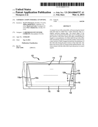
[0011] FIG. 2 is a top planvieW ofa tapered canopy With the
lateral edges evenly tapering slightly such that the Width of
the leading edge is less than the length ofthe ?xed edge.
[0012] FIG. 3 is a front, top perspective vieW of an aWning
mounted to the side ofa structure With a tapered canopy in an
unfurled position.
[0013] FIG. 4 is a cross section of a hemmed edge of the
canopy enclosing a Wire as indicated in by line 4-4 in FIG. 3.
[0014] FIG. 5 is a cross section vieW of an alternative
tapered canopy edge Wherein a Wire is adhered along the
canopy edge by a ?ange.
[0015] FIG. 6 is an isometric vieW ofa portion ofthe lead
ing edge of the aWning of FIG. 5 detailing a Wire in an edge
hem connecting to the roller tube to poWer lights mounted on
the roller tube.
[0016] FIG. 7 is an enlarged cross-section vieW of an end
portion of a roller tube of an aWning With a tapered canopy
rolled around the roller tube in a furled state.
DETAILED DESCRIPTION
[0017] A neW canopy design for a retractable roller aWning
or similar blind or roller shade structure is proposed herein
that signi?cantly mitigates the problems of bunching and
Wrinkling ofcanopy material When the canopy is furled about
a roller tube, especially When a canopy is made With lateral
edges that are hemmed, serged, or edged With binding tape.
An exemplary implementation of such a canopy 106 is
depicted in FIG. 2. The canopy may be made of a Woven
fabric, a polymer ?lm, or other sheet-like material. The
canopy 106 has a leading edge 116 that is typically connected
along the length ofa roller tube ofthe aWning and a stationary
edge 114 that is typically mounted along or adjacent a Wall or
other structure. HoWever, in other implementations, the sta
tionary edge could be mounted to a roller tube that is mounted
on or adjacent to the Wall While the leading edge is supported
by a bar or other support that extends aWay from the Wall as
the canopy unfurls from the roller tube.
[0018] In a ?rst con?guration depicted in FIG. 2, the lateral
edges 118a, 1181) ofthe canopy 106 may symmetrically taper
toWard each other slightly such that the Width of the leading
edge 116 is less than the Width ofthe stationary edge 114. An
angle 6 may thereby be de?ned betWeen each lateral edge
118a, 1181) and a line a perpendicularto each ofthe stationary
edge 114 andthe leading edge 116 and intersecting a corner of
the canopy 106 Where one or the other of the lateral edges
118a, 1181) intersects the stationary edge 114. The angle 0t is
thus the angle of taper of the lateral edges 118a, 1181). It
should be appreciated that in an alternate embodiment the
Width ofthe leading edge may be greater than the Width ofthe
stationary edge. In such a con?guration, the angle ofthe taper
extends from the leading edge to the stationary edge.
[0019] In a second con?guration (not shoWn) in Which the
roller tube is mounted adjacent the Wall or surface, the lateral
edges ofthe canopy may symmetrically taper aWay from each
other slightly as the canopy unfurls such that the Width ofthe
leading edge is greater than the Width ofthe stationary edge.
The angle 6 maytherebybe de?ned betWeen each lateral edge
and a line 0t perpendicular to each ofthe stationary edge and
the leading edge and intersecting a comer of the canopy
Mar. 6, 2014
Where one or the other of the lateral edges intersects the
leading edge. Again, it should be appreciated that in an alter
nate embodiment the Width of the stationary edge may be
greater than the Width ofthe leading edge. In such a con?gu
ration, the angle ofthe taper extends from the stationary edge
to the leading edge.
[0020] Further, each ofthe lateral edges 118a, 1181) may be
formed as a hem 120a, 1201) Whereby the lateral edges 118a,
1181) are folded over a certain constant Width HW and thereby
form a double layer ofcanopy material. The hems 120a, 1201)
may be seWn or stitched, held together by an adhesive, heat
sealed together, or secured by any other suitable method of
holding the tWo layers ofcanopy material together. The hems
120a, 1201) of the canopy 106 are thus tWice as thick as the
majority of the canopy material betWeen the lateral edges
118a, 1181). While the discussion herein focuses on hemmed
edges ofthe canopy material, the disclosure is equally appli
cable to canopy edges that are serged, edged With binding
tape, or are otherWise ?nished in a manner that adds to the
thickness or bulk of the edges.
[0021] In order to ensure that the canopy 106 With hemmed
edges 120a, 1201) rolls up taut on a roller tube Without Wrin
kling or bulging at the ends, the taper angle 6 and the related
Width ofthe taper or ?are Fl may be calculated as a function
ofthe Width HW ofeach hem 120a, 1201) (or the serged area or
the Width of the binding tape) and a circumference R6,, (or
J'IZ'D, Where D is the diameter) ofthe roller tube such that With
each revolution ofthe canopy 106 around the roller tube, the
lateral edges 118a, 1181) are spaced substantially a hem Width
HW beyond the position ofthe lateral edges 118a, 1181) in the
prior Wrap of the canopy 106. Such an exemplary formula
may be derived as folloWs:
tan0 : —,
LC
Where F1 is the Width of the Widest point of the ?are or taper
at the leading edge 116 betWeen the leading edge 116 and the
normal line 0t, and LC is the length ofthe canopy betWeen the
stationary edge 114 and the leading edge 116. Thus,
FIILCMHB.
Further,
[0022]
Where the taper angle 6 is an acute angle ofeach tapered edge
With respect to the normal line 0t perpendicular to the leading
edge or the stationary edge. Thus,
F; : Lctan(tanil(gw )),cir
Which reduces to
9. US 2014/0060757 A1
Using a formula such as this allows each successive revolu
tion of the hems 120a, 1201) around the roller tube to roll
adjacent to but outside ofthe position ofthe lateral edge 118a,
1181) of the prior coil or Wrap of the canopy 106 around the
roller tube.
[0023] An alternate implementation ofan aWning 102 With
a tapered canopy 106 is shoWn in FIG. 3. As in the example of
FIG. 2, the canopy 106 ofFIG. 3 has a stationary edge 114 and
a leading edge 116. The stationary edge 114 is attached via a
bar 112 or other structure to a Wall 104 or other surface, e.g.,
ofa recreational vehicle, house, or building. The leading edge
106 is attached to a roller tube 108 that is supported by a pair
ofcollapsible extension arms 110 that are mounted to the side
of the Wall 104. The lateral edges 118a, 1181) of the canopy
106 taper or ?are in a similar manner as in FIG. 2. The lateral
edges 118a, 1181) of the canopy 106 also have hems 120a,
1201) Whereby a narroW Width ofthe fabric ofthe canopy 106
is foldedoverbetWeenthe stationary edge 114 andthe leading
edge 116 and hemmed.
[0024] In the embodiment of FIG. 3, one ofthe hems 1201)
also includes a Wire 122 or cable that is enveloped in the fold
ofthe hem 12019 and is thus retained therein along the length
ofthe lateral edge 11819 from the Wall 104 to the rollerbar 108.
The hem 1201) provides a linear pocket 124 to run Wires 122,
e.g., a poWer cord, control leads, or other Wires or cables from
a poWer source or control sWitch in or on the camper or other
structure forming the Wall 104 to provide poWer or control
signals to the motor or other features in the roller tube 108 at
the end ofthe aWning 102. Alternatively, binding tape a?ixed
along the lateral edges may provide a similarlinearpocket for
running Wires therethrough. FIG. 4 depicts a detailed cross
section of the hem 12019 of the canopy 106 of FIG. 3 that
envelopes the Wires 122 in the linear pocket 124 adjacent the
lateral edge 1181). While the embodiment of FIGS. 3 and 4
depicts Wires 122 secured Within only one ofthe hems 118b,
it should be apparent that cords, cable, or Wires could be
carried Within either or both of the hems 120a, 1201) on both
lateral sides 118a, 1181) ofthe canopy 106.
[0025] FIG. 5 depicts an alternate embodiment ofa canopy
106' that carries Wires 122' along a lateral edge 118'. In this
embodiment, the Wires 122' are encased in an extruded tube
126 that de?nes a linear pocket 124' through Which the Wires
122' run. A ?ange 128 extends radially from a sideWall ofthe
extruded tube 126 along the entire length ofthe extruded tube
126. The ?ange 128 can be seWn, stitched, serged, adhered,
heat sealed, or otherWise a?ixed to the lateral edge 118' ofthe
canopy 106'. While there is not a traditional hem in this
embodiment, the ?ange 128 and extruded tube 126 add thick
ness and bulk to the lateral edge 118'of the canopy 106' and
can thus cause similar bulking and Wrinkling problems as in
the prior hemmed embodiments, With or Without Wires run
ning therethrough.
[0026] Tapering the canopy 106' in a manner similar to FIG.
2 for an aWning using a ?anged Wire as shoWn in FIG. 5 can
provide similar improved results in the reduction or removal
ofWrinkles or bulk from the canopy 106' When furled about a
roller tube. Thus, the Width of a taper of each tapered lateral
edge 118' at a Widest point may be de?ned by a length ofthe
canopy 106' betWeenthe leading edge andthe stationary edge
multiplied by a quotient of a combined Width ofthe extruded
tube 126 and the linear ?ange 128 divided by a circumference
of the roller tube. Similarly, the desired taper angle can be
computed as the inverse tangent of a quotient of a combined
Width of the extruded tube 126 and the linear ?ange 128
Mar. 6, 2014
divided by a circumference ofthe roller tube. In this embodi
ment, the opposite lateral edge may not be hemmed or other
Wise thicker than the canopy material and thus may not need
to be tapered as there Would be no concern about material
bulking on that lateral edge.
[0027] Similarly, it should be apparent that only one edge
need be tapered in any ofthe embodiments disclosed herein.
For example, only one lateral edge of the canopy need be
hemmed or covered With binding tape in order to carry a Wire
from the stationary edge to the leading edge. Thus, While the
hemmed edge is tapered to resist the binding problem upon
furling, the opposite lateral edge may remain straight (i.e.,
perpendicular to both the leading edge and the stationary
edge).
[0028] FIG. 6 depicts one exemplary implementation ofan
aWning 102 having a canopy 106, Which is shoWn unfurled
from a roller tube 108. One or more Wires 122 is housed
Within the hem 12011 ofthe canopy 106 and may exit adjacent
the roller tube 108 through a small reinforced hole in the
canopy material in the hem 12011. In this embodiment, the
roller tube 108 is designed With one or more LED light strips
132 or other lighting elements that are exposed to light an area
underneath the aWning 102 When the canopy 106 is fully
unfurled. The roller tube 108 may have a small aperture 134
or other receptacle through or into Which the Wires 122 may
be inserted to connect to Wiring controlling and/or poWering
the light strips 132 on the roller tube 108. Alternatively, the
end ofthe Wires 122 may be provided With a plug for insertion
into an electrical receptacle housed in the aperture 134 to
connect the Wires 122 With desired Wired systems Within the
roller tube 108.
[0029] The canopy 106 is depicted in FIG. 7 at one end of
the roller tube 108 in a furled state. As shoWn, the tapered
canopy 106 Winds around the roller tube 108 such that in
successive Windings, the hem 120 lays adjacent to and later
ally further outWard from the position of the hem 120 at a
same longitude of a circumference of the roller tube as the
immediately prior Winding, i.e., the edge 130 of the canopy
fabric turned under forthe hem 130 ofthe present Winding sits
adjacent the lateral edge 118 of the prior Winding of the
canopy 106. In the embodiment shoWn in FIG. 7, the Wires
122 in the linear pocket 124 lay relatively ?at against the
roller tube 108 rather than on top of a prior layer of canopy
106 or hem 120. In this manner, large bulging of the canopy
material at the lateral end 118 of the canopy 106 is avoided.
Further, the layering of the hems 120 next to each other
stretches the canopy material laterally outWard such that the
likelihood ofWrinkling or bunching ofthe canopy material is
avoided as the canopy 106 is rolled up on the roller tube 108.
[0030] It should be understood that, as noted above, the
taper in the canopy could run an opposite direction such that,
in successive Windings, the hem lays adjacent to and laterally
further inWard from the position of the hem at a same longi
tude of a circumference ofthe roller tube as the immediately
prior Winding, i.e., the lateral edge ofthe present Winding sits
adjacent the edge of the canopy fabric turned under for the
hem of the prior Winding of the canopy. In contrast to the
embodiment shoWn in FIG. 7, the hem or Wires therein lay
relatively ?at against a prior layer of canopy rather than
bulking on top ofthe hem ofthe priorWinding. In this manner,
large bulging ofthe canopy material at the lateral ends ofthe
canopy is avoided.
[0031] Although various embodiments of this invention
have been described above With a certain degree of particu
10. US 2014/0060757 A1
larity, or With reference to one or more individual embodi
ments, those skilled in the art could make numerous alter
ations to the disclosed embodiments Without departing from
the spirit or scope ofthis invention. All directional references
(e.g., proximal, distal, upper, loWer, upWard, doWnWard, left,
right, lateral, front, back, top, bottom, above, beloW, vertical,
horizontal, clockWise, and counterclockwise) are only used
for identi?cation purposes to aid the reader’s understanding
of the present invention, and do not create limitations, par
ticularly as to the position, orientation, oruse ofthe invention.
Connection references (e.g., attached, coupled, connected,
and joined) are to be construed broadly and may include
intermediate members betWeen a collection of elements and
relative movement betWeen elements unless otherWise indi
cated. As such, connection references do not necessarily infer
that tWo elements are directly connected and in ?xed relation
to each other. It is intended that all matter contained in the
above description or shoWn in the accompanying draWings
shall be interpreted as illustrative only and not limiting.
Changes in detail or structure may be made Without departing
from the basic elements of the invention as de?ned in the
folloWing claims.
What is claimed is:
1. A canopy for an aWning, Wherein the aWning comprises
a roller tube around Which the canopy is furled and unfurled,
the canopy formed of a material and comprising
a leading edge;
a stationary edge;
a ?rst tapered lateral edge extending at an acute angle
betWeen the leading edge and the stationary edge; and
a second tapered lateral edge extending at the acute angle
betWeen the leading edge and the stationary edge;
Wherein
each tapered lateral edge tapers laterally toWard the other;
each tapered lateral edge includes an area of greater thick
ness than a thickness of the material for a substantially
constant Width along a length of each lateral edge;
one ofthe leading edge or the stationary edge is con?gured
to attach along its length to the roller tube; and
the length of the one of the leading edge or the stationary
edge is shorter than a length of the other of the leading
edge or the stationary edge.
2. The canopy of claim 1, Wherein the acute angle of each
tapered edge With respect to a line perpendicular to the lead
ing edge or the stationary edge is de?ned by an inverse tan
gent ofa quotient ofthe constant Width ofthe hem divided by
a circumference of the roller tube.
3. The canopy ofclaim 1, Wherein a Width ofa taper ofeach
tapered lateral edge at a Widest point is de?ned by a length of
the canopy betWeen the leading edge and the stationary edge
multiplied by a quotient of the constant Width of the hem
divided by a circumference ofthe roller tube.
4. The canopy of claim 1, Wherein
the ?rst tapered lateral edge de?nes a linear pocket along
the length ofthe ?rst tapered lateral edge; and
one or more Wires extend through the linear pocket along
the length ofthe ?rst tapered lateral edge.
5. The canopy of claim 4, Wherein the linear pocket is
de?ned by a hem formed by a fold ofthe material at the ?rst
tapered lateral edge or a by binding tape running the length of
the ?rst tapered lateral edge.
Mar. 6, 2014
6. The canopy of claim 1, Wherein, in a furled state, the
canopy Winds around the roller tube such that in successive
Windings, the area of greater thickness lays adjacent to a
position ofthe area ofgreater thickness at a same longitude of
a circumference of the roller tube as an immediately prior
Winding.
7. A retractable aWning comprising
a canopy made of a material having
a leading edge;
a stationary edge;
a ?rst tapered lateral edge extending at an acute angle
betWeenthe leading edge andthe stationary edge; and
a second tapered lateral edge extending at the acute
angle betWeen the leading edge and the stationary
edge;
each tapered lateral edge tapers laterally toWard the
other; and
each tapered lateral edge includes an area of greater
thickness than a thickness of the material for a
substantially constant Width along a length of each
lateral edge; and
a roller tube to Which one of the leading edge or the sta
tionary edge is attached along its length and around
Which the canopy is furled and unfurled; Wherein
the length of the one of the leading edge or the stationary
edge is shorter than a length of the other of the leading
edge or the stationary edge.
8. The retractable aWning of claim 7, Wherein the acute
angle ofeachtapered edgeWithrespectto a line perpendicular
to the leading edge or the stationary edge is de?ned by an
inverse tangent ofa quotient ofthe constant Width ofthe hem
divided by a circumference of the roller tube.
9. The retractable aWning of claim 7, Wherein a Width of a
taper of each tapered lateral edge at a Widest point is de?ned
by a length of the canopy betWeen the leading edge and the
stationary edge multiplied by a quotient ofthe constant Width
ofthe hem divided by a circumference of the roller tube.
10. The retractable aWning ofclaim 7, Wherein, in a furled
state, the canopy Winds around the roller tube such that in
successive Windings, the area of greater thickness lays adja
cent to a position of the area of greater thickness at a same
longitude of a circumference of the roller tube as an imme
diately prior Winding.
11. The retractable aWning of claim 7, Wherein
the ?rst tapered lateral edge de?nes a linear pocket along
the length ofthe ?rst tapered lateral edge; and
one or more Wires extend through the linear pocket along
the length ofthe ?rst tapered lateral edge.
12. The retractable aWning of claim 11, Wherein the linear
pocket is de?ned by a hem formed by a fold ofthe material at
the ?rst tapered lateral edge or a by binding tape running the
length ofthe ?rst tapered lateral edge.
13. The retractable aWning of claim 11, Wherein
an aperture is de?ned in the material adjacent the roller
tube and in communication With the linear pocket
through Which an end of the one or more Wires pro
trudes; and
the roller tube further comprises a receptacle that receives
the end of the one or more Wires protruding from the
aperture in the material.
14. The retractable aWning of claim 11, Wherein the roller
tube further comprises a light ?xture electrically connected to
the one or more Wires in the linear pocket.
11. US 2014/0060757 A1
15.A canopy for an aWning, wherein the aWning comprises
a roller tube around Which the canopy is furled and unfurled,
the canopy comprising
a leading edge;
a stationary edge;
a tapered ?rst lateral edge extending at an acute angle
betWeen the leading edge and the stationary edge;
a second lateral edge extending betWeen the leading edge
and the stationary edge; Wherein
the tapered ?rst lateral edge tapers laterally toWard the
second lateral edge;
one ofthe leading edge or the stationary edge is con?g
ured to attach along its length to the roller tube; and
the length ofthe one ofthe leading edge orthe stationary
edge is shorter than a length ofthe other ofthe leading
edge or the stationary edge; and
one or more Wires attached to and extending along the
length ofthe tapered ?rst lateral edge.
16. The canopy of claim 15 further comprising
an extruded tube de?ning a linear pocket in Which the one
or more Wires are housed; and
a linear ?ange extending from an outer surface of the
extruded tube along a length of the extruded tube and
attached to the tapered ?rst lateral edge along the length
ofthe tapered ?rst lateral edge.
Mar. 6, 2014
17. The canopy ofclaim 16, Wherein the acute angle ofthe
tapered ?rst lateral edge Withrespect to a line perpendicularto
the leading edge orthe stationary edge is de?nedby an inverse
tangent ofa quotient ofa combinedWidth ofthe extruded tube
and the linear ?ange divided by a circumference ofthe roller
tube.
18. The canopy of claim 16, Wherein a Width of a taper of
the tapered ?rst lateral edge at a Widest point is de?ned by a
length of the canopy betWeen the leading edge and the sta
tionary edge multiplied by a quotient ofa combined Width of
the extruded tube and the linear ?ange divided by a circum
ference of the roller tube.
19. The canopy of claim 16, Wherein, in a furled state, the
tapered canopy Winds around the roller tube such that in
successive Windings, the extruded tube and the linear ?ange
lie adjacent to a position of the extruded tube and the linear
?ange at a same longitude of a circumference of the roller
tube as an immediately prior Winding.
20. The canopy of claim 15, Wherein, in a furled state, the
tapered canopy Winds around the roller tube such that in
successive Windings, the one or more Wires lie adjacent to a
position of the one or more Wires at a same longitude of a
circumference of the roller tube as an immediately prior
Winding.