SlideShare a Scribd company logo
1 of 23
Download to read offline
Lesson Title: Resistors
Lesson Outcomes:
At the end of this topic, the student should be able to:
1. Identify the function of the resistor in an electronic device
2. Categorize the different types of Resistors
3. Identify the color-coded values of the Resistors
4. List how Ohm’s Law works
5. Calculate the Total Resistance of circuit in a Series and Parallel connections manually
Lesson Contents:
A resistor is a passive two-terminal electrical component that implements electrical resistance as a
circuit element. Resistors act to reduce current flow, and, at the same time, act to lower voltage levels
within circuits. In electronic circuits, resistors are used to limit current flow, to adjust signal
levels, bias active elements, and terminate transmission lines among other uses.
The two main characteristics of a resistor are its resistance R in ohms and its power rating in watts (W).
Resistors are available in a very wide range of R values, from a fraction of an ohm to many kilo ohms
(kΩ) and mega ohms (MΩ). One kilo ohm is 1000 Ω and one mega ohm is 1,000,000 Ω. The power rating
for resistors may be as high as several hundred watts or as low as 1 ⁄ 10 W.
Types of Resistor
1. Wire-Wound Resistors
In this construction, a special type of wire called resistance wire is wrapped around an insulating core.
Types of resistance wire include tungsten and manganin. The insulated core is commonly porcelain,
cement, or just plain pressed paper. Bare wire is used, but the entire unit is generally encased in an
insulating material. Typical fixed and variable wire-wound resistors are shown in Figure 2.1.
Figure 2.1. Wire Wound Resistors
Since they are generally used for high-current applications with low resistance and appreciable power,
wire-wound resistors are available in wattage ratings from 1 W up to 100 W or more. The resistance can
be less than 1 Ω up to several thousand ohms. For 2 W or less, carbon resistors are preferable because
they are generally smaller and cost less.
In addition, wire-wound resistors are used where accurate, stable resistance values are necessary.
Examples are precision resistors for the function of an ammeter shunt or a precision potentiometer to
adjust for an exact amount of resistance.
2. Carbon-Composition Resistors
These resistors are made of finely divided carbon or graphite mixed with a powdered insulating material
as a binder in the proportions needed for the desired resistance value. As shown in Figure 2.2 the
resistor element is enclosed in a plastic case for insulation and mechanical strength. Joined to the two
ends of the carbon resistance element are metal caps with leads of tinned copper wire for soldering the
connections into a circuit. These are called axial leads because they come straight out from the ends.
Carbon-composition resistors normally have a brown body and are cylindrical. Carbon-composition
resistors are commonly available resistance values of 1 Ω to 20 M Ω. Examples are 10 Ω, 220 Ω, 4.7 k Ω,
and 68 k Ω. The power rating is generally 1 ⁄ 10, 1 ⁄ 8, 1 ⁄ 4, 1 ⁄ 2, 1, or 2 W.
Figure 2.2. Construction and Wattage of Carbon-Composition Resistors
3. Film-Type Resistors
There are two kinds of film-type resistors: carbon-film and metal-film resistors. The carbon-film resistor,
whose construction is shown in Fig. 2–4, is made by depositing a thin layer of carbon on an insulated
substrate. The carbon film is then cut in the form of a spiral to form the resistive element. The resistance
value is controlled by varying the proportion of carbon to insulator. Compared to carbon-composition
resistors, carbon-film resistors have the following advantages: tighter tolerances, less sensitivity to
temperature changes and aging, and they generate less noise internally.
Metal-film resistors are constructed in a manner similar to the carbon-film type. However, in a metal-
film resistor, a thin film of metal is sprayed onto a ceramic substrate and then cut in the form of a spiral.
The construction of a metal-film resistor is shown in Fig. 2–5. The length, thickness, and width of the
metal spiral determine the exact resistance value. Metal-film resistors offer more precise R values than
carbon-film resistors. Like carbon-film resistors, metal-film resistors are affected very little by
temperature changes and aging. They also generate very little noise internally. In overall performance,
metal-film resistors are the best, carbon-film resistors are next, and carbon-composition resistors are
last. Both carbon- and metal-film resistors can be distinguished from carbon-composition resistors by
the fact that the diameter of the ends is a little larger than that of the body. Furthermore, metal-film
resistors are almost always coated with a blue, light green, or red lacquer which provides electrical,
mechanical, and climate protection. The body color of carbon-film resistors is usually tan.
Figure 2.3. Construction of Film Type Resistors
4. Surface-Mount Resistors
Surface-mount resistors, also called chip resistors, are constructed by depositing a thick carbon film on a
ceramic base. The exact resistance value is determined by the composition of the carbon itself, as well
as by the amount of trimming done to the carbon deposit. The resistance can vary from a fraction of an
ohm to well over a million ohms. Power dissipation ratings are typically 1 ⁄ 8 to ¼ W. Figure 2.4 shows
typical chip resistors. Electrical connection to the resistive element is made via two leadless solder end
electrodes (terminals). The end electrodes are C-shaped. The physical dimensions of a 1 ⁄ 8 -W chip
resistor are 0.125 in. long by 0.063 in. wide and approximately 0.028 in. thick. This is many times smaller
than a conventional resistor having axial leads. Chip resistors are very temperature-stable and also very
rugged. The end electrodes are soldered directly to the copper traces of a circuit board, hence the name
surface-mount.
5. Fusible Resistors
This type is a wire-wound resistor made to burn open easily when the power rating is exceeded. It then
serves the dual functions of a fuse and a resistor to limit the current.
Figure 2.5. Fusible Resistor
6. Thermistors
A thermistor is a thermally sensitive resistor whose resistance value changes with changes in operating
temperature. Because of the self-heating effect of current in a thermistor, the device changes resistance
with changes in current. Thermistors, which are essentially semiconductors, exhibit either a positive
temperature coefficient (PTC) or a negative temperature coefficient (NTC). If a thermistor has a PTC, its
resistance increases as the operating temperature increases. Conversely, if a thermistor has an NTC, its
resistance decreases as its operating temperature increases. How much the resistance changes with
changes in operating temperature depends on the size and construction of the thermistor. Note that the
resistance does not undergo instantaneous changes with changes in the operating temperature. A
certain time interval, determined by the thermal mass (size) of the thermistor, is required for the
resistance change. A thermistor with a small mass will change more rapidly than one with a large mass.
Carbon- and metal-film resistors are different: their resistance does not change appreciably with
changes in operating temperature.
Figure 2.6.a. shows the standard schematic symbol for a thermistor. Notice the arrow through the
resistor symbol and the letter T within the circle. The arrow indicates that the resistance is variable as
the temperature T changes. As shown in Figure 2.6.b., thermistors are manufactured in a wide variety of
shapes and sizes. The shapes include beads, rods, disks, and washers.
Thermistors are frequently used in electronic circuits in which it is desired to provide temperature
measurement, temperature control, and temperature compensation.
Figure 2.6. Symbol and Types of Thermistor
7. Varistor
Varistors are voltage-dependent resistors. This means that their resistance is dependent on the voltage
across them.
Figure 2.7. Varistor
Reading the coded value
The resistance value of a carbon resistor is color coded. There are four color bands printed on the body
of a resistor. Each color represents a number. The color band which is closest to the left hand position of
the resistor is the first color. An easy way to determine the first left hand color band is that of the color
itself. The black color, for example, is not used for the first color or first digit. Gold and silver is for the
third and fourth colors. When used as the third color it signifies the multiplier. The fourth color
represents tolerance. The color coding is standardized by the Electronic Industries Alliance (EIA).
See table below:
Table 2.1. Color Equivalent
Note: To determine the coded value of the resistor all you have to do is to write the first and
second significant digit followed by the multiplier or number of zeroes that you are going to add after
the second significant digit then write the unit and the percent of tolerance.
Examples:
1. The value of a resistor is 10 ohms with a tolerance of 5%.Let us find out from the color code
table what would be the color bands of the resistor in figure 1.
Figure 2.8. 1st
Example of reading resistance.
The color that you have located in the table should match the colors in the first example.
Continue checking with example number 2.
2. The value of the resistor is 100 ohms with a tolerance of 10%.
Figure 2.9. 2nd
Example of reading resistance
Variable Resistors
Variable resistors can be wire-wound or carbon type, illustrated in Figure 2.10.a. inside the metal case,
the control has a circular disk, shown in Figure 2.10.b, that is the carbon-composition resistance
element. It can be a thin coating on pressed paper or a molded carbon disk. Joined to the two ends are
the external soldering-lug terminals 1 and 3. The middle terminal is connected to the variable arm that
contacts the resistor element by a metal spring wiper. As the shaft of the control is turned, the variable
arm moves the wiper to make contact at different points on the resistor element. The same idea applies
to the slide control in Figure 2.11, except that the resistor element is straight instead of circular. When
the contact moves closer to one end, the R decreases between this terminal and the variable arm.
Between the two ends, however, R is not variable but always has the maximum resistance of the
control. Carbon controls are available with a total R from 1000 Ω to 5 M Ω, approximately. Their power
rating is usually 1 ⁄ 2 to 2 W.
Figure 2.10. Construction of Variable Resistor
Types of Variable Resistors
1. Tapered Controls
The way R varies with shaft rotation is called the taper of the control. With a linear taper, a one-half
rotation changes R by one-half the maximum value. Similarly, all values of R change in direct proportion
to rotation. For a nonlinear taper, though, resistance can change more gradually at one end with bigger
changes at the opposite end. This effect is accomplished by different densities of carbon in the
resistance element. For a volume control, its audio taper allows smaller changes in resistance at low
settings. Then it is easier to make changes without having the volume too loud or too low.
Figure 2.11. Tapered Controls
2. Decade Resistance Box
As shown in Figure 2.12, the decade resistance box is a convenient unit for providing any one R within a
wide range of values. It can be considered test equipment for trying different R values in a circuit. Inside
the box are six series strings of resistors, with one string for each dial switch.
The first dial connects in an R of 0 to 9 Ω. It is the units or R x 1 dial.
The second dial has units of 10 from 0 to 90 Ω. It is the tens or R x 10 dial.
The hundreds or R x 100 dial has an R of 0 to 900 Ω.
The thousands or R x 1 k dial has an R of 0 to 9000 Ω.
The ten-thousands or R x 10 k dial provides R values of 0 to 90,000 Ω.
The one-hundred-thousand or x 100 k dial provides R values of 0 to 900,000 Ω.
The six dial sections are connected internally so that their values add to one another. Then any value
from 0 to 999,999 Ω can be obtained. Note the exact values that are possible. As an example, when all
six dials are on 2, the total R equals 2 + 20 + 200 + 2000 + 20,000 + 200,000 + 222,222 Ω.
Figure 2.12. Decade Resistance Box
3. Rheostats and Potentiometers
Rheostats and potentiometers are variable resistances, either carbon or wire-wound, used to vary the
amount of current or voltage in a circuit. The controls can be used in either dc or ac applications.
A rheostat is a variable R with two terminals connected in series with a load. The purpose is to vary the
amount of current.
A potentiometer, generally called a pot for short, has three terminals. The fixed maximum R across the
two ends is connected across a voltage source. Then the variable arm is used to vary the voltage division
between the center terminal and the ends.
A potentiometer can act as a rheostat by connecting one end of the control and the variable arm, using
only two terminals. The third terminal is open, or floating, not connected to anything. Another method
is to wire the unused terminal to the center terminal. When the variable arm is rotated, different
amounts of resistance are short-circuited. This method is preferable because there is no floating
resistance.
Figure 2.13. Rheostats and Potentiometers
Series and Parallel Combinations of Resistors
 Resistor Connection:
There are three common methods of connecting resistors together. These connections are series,
parallel and series parallel.
Series:
In series connection two or more resistors are tied together like a chain. The individual resistances are
added up for the total resistance. For example, there are three resistors connected in series. Each
resistor has a resistance of 10 ohms (Figure 2.14).
Figure 2.14. Series Connection
The formula for series resistance will be: Rt = R1 + R2 + R3 where Rt is the total resistance and
R1, R2, R3 represent individual resistances. In this example the total resistance is computed as Rt = 10 +
10 + 10 = 30 ohms. The power or wattage of each resistor connected in series is similarly added for the
total wattage. For example, we have two resistors connected in series and each resistor is ½ watt. The
total wattage of the two will be 1 watt.
Parallel:
In parallel connection two or more resistors are connected as shown in Figure 2.14. In this
method of connection the individual resistances are not added. Simplifying solutions for determining the
total resistance of parallel resistors we can adopt the following method. If two or more resistors with
the same values are in parallel simply divide the value of one resistor by the number of resistors.
If there are two resistors of unequaled values connected in parallel the total resistance is
smaller than the lowest value of an individual resistor in the circuit. The formula is:
Rt = multiply 2 values / add 2 values
When there are three or more resistors of different values in parallel the formula will be:
Instead of solving though the reciprocal formula the total resistance of a parallel connection can
be calculated through the mentioned earlier formula of product over sum. The solution will be longer,
however, the end result will be the same. First, compute for the total resistance of two resistors. After
that take the total resistance of the first two, considered as one, and compute with another resistor
which is in parallel with the first two. Having arrived at the total resistance of the three resistors you can
go on computing for any additional number of resistors using the same method.
Note: In the case of series connection, the combined resistance value increases as the number of
resistors in the connection becomes large and decreases in parallel connection as the number of
resistors in the connection increases.
Series Parallel Connection
In practice, there are instances when resistors have no exact replacements available. Depending
on the available values on hand a series parallel substitution can be installed. A series parallel circuit is a
combination of two or more circuits in parallel with each circuit being a series connection. An example
of series parallel connection is shown in figure 8. R1 and R2 are in series connection; R3 and R4 are also
series. By joining the two series connections into a parallel connection a series parallel connection is
formed.
To solve for Rt:
R1 and R2 are connected in series, so let’s assume Ra = R1 + R2
R3 and R4 are also connected in series, then Rb = R3 + R4
Rt = Ra Rb / Ra +Rb , we use this formula because Ra and Rb are connected in parallel
In any case of resistor replacement whether it is single, series or parallel the value of a new resistor or a
total value of a group of resistors should be equal or very close to the original resistor.
The original wattage of the resistor to be replaced should also be taken into consideration and matched
closely. For example, do not replace a 5-watt resistor with another one of, say, 1 watt. The same is true
with a small wattage resistor being replaced by a larger one. This will result in a shorter life if not in an
instant damage. The wattage of a resistor does not affect or alter its resistance value but it certainly
affects its performance if wattage is not properly chosen.
Ohm’s Law
Before we proceed with ohm’s law let us refresh our mind first with the basic electricity.
All the materials we know, including solids, liquids, and gases, contain two basic particles of electric
charge: the electron and the proton. An electron is the smallest amount of electric charge having the
characteristic called negative polarity. The proton is a basic particle with positive polarity.
The negative and positive polarities indicate two opposite characteristics that seem to be fundamental
in all physical applications. Just as magnets have north and south poles, electric charges have the
opposite polarities labeled negative and positive. The opposing characteristics provide a method of
balancing one against the other to explain different physical effects.
It is the arrangement of electrons and protons as basic particles of electricity that determines the
electrical characteristics of all substances. As an example, this paper has electrons and protons in it.
There is no evidence of electricity, though, because the number of electrons equals the number of
protons. In that case, the opposite electrical forces cancel, making the paper electrically neutral. The
neutral condition means that opposing forces are exactly balanced, without any net effect either way.
When electrons can move easily from atom to atom in a material, the material is a conductor. In
general, all metals are good conductors, with silver the best and copper second. Copper wire is generally
used for practical conductors because it costs much less than silver. The purpose of using conductors is
to allow electric current to flow with minimum opposition.
The wire conductor is used only to deliver current produced by the voltage source to a device that needs
the current to function. As an example, a bulb lights only when current flows through the filament.
A material with atoms in which the electrons tend to stay in their own orbits is an insulator because it
cannot conduct electricity very easily. However, insulators can hold or store electricity better than
conductors. An insulating material, such as glass, plastic, rubber, paper, air, or mica, is also called a
dielectric, meaning it can store electric charge.
Insulators can be useful when it is necessary to prevent current fl ow. In addition, for applications
requiring the storage of electric charge, as in capacitors, a dielectric material must be used because a
good conductor cannot store any charge.
Carbon can be considered a semiconductor, conducting less than metal conductors but more than
insulators. In the same group are germanium and silicon, which are commonly used for transistors and
other semiconductor components. Practically all transistors are made of silicon.
Electric charge is the physical property of matter that causes it to experience a force when placed in an
electromagnetic field. There are two types of electric charges: positive and negative. Positively charged
substances are repelled from other positively charged substances, but attracted to negatively charged
substances; negatively charged substances are repelled from negative and attracted to positive. An
object is negatively charged if it has an excess of electrons, and is otherwise positively charged or
uncharged.
The coulomb (unit symbol: C) is the International System of Units (SI) unit of electric charge. It is the
charge (symbol: Q or q) transported by a constant current of one ampere in one second. It is named
after Charles-Augustin de Coulomb a French Physicist.
An electric current is a flow of electric charge. In electric circuits this charge is often carried by
moving electrons in a wire. It can also be carried by ions in an electrolyte, or by both ions and electrons.
The ampere (SI unit symbol: A), is the unit of electric current. It is named after André-Marie
Ampère (1775–1836), French mathematician and physicist, considered the father of electrodynamics.
Amperes are used to express flow rate of electric charge.
Voltage, electric potential difference, electric pressure or electric tension is the difference in electric
potential energy between two points per unit electric charge. The voltage between two points is equal
to the work done per unit of charge against a static electric field to move the charge between two points
and is measured in units of volts (a joule per coulomb).
The volt (symbol: V) is the derived unit for electric potential, electric potential difference (voltage),
and electromotive force. The volt is named in honor of the Italian physicist Alessandro Volta (1745–
1827), who invented the voltaic pile, possibly the first chemical battery.
Resistance is the opposition that a substance offers to the flow of electric current. It is represented by
the uppercase letter R.
The ohm (symbol: Ω) is the unit of electrical resistance, named after German physicist Georg Simon
Ohm.
Now that we already have the knowledge of basic electricity we are now ready to face the Ohm’s Law.
The relationship between voltage, current, and resistance was discovered in 1826 by Georg Simon Ohm.
The relationship, known as Ohm’s law, is the basic foundation for all circuit analysis in electronics. Ohm’s
law, which isthe basis of this chapter, states that the amount of current, I, is directly proportional to the
voltage, V, and inversely proportional to the resistance, R. Expressed mathematically, Ohm’s law is
stated as I = V/R
Electric power is the rate at which electrical energy is transferred by an electric circuit. It is usually
produced by electric generators, but can also be supplied by sources such as electric batteries. It is
generally supplied to businesses and homes by the electric power industry through an electric power
grid
Electric power is the rate of doing work, measured in watts, and represented by the letter P. The
term wattage is used colloquially to mean "electric power in watts." The electric power
in watts produced by an electric current I consisting of a charge of Q coulombs every t seconds passing
through an electric potential (voltage) difference of V is
Where:
Q is electric charge in coulombs
t is time in seconds
I is electric current in amperes
V is electric potential or voltage in volts
Series and Parallel Circuit Analysis
General Methods for Series Circuits
For other types of problems with series circuits, it is useful to remember the following:
1. When you know the current (I) for one component, use this value for I in all components, for the
current is the same in all parts of a series circuit.
2. To calculate current (I), the total VT can be divided by the total RT, or an individual IR drop can be
divided by its R. However, do not mix a total value for the entire circuit with an individual value
for only part of the circuit.
3. When you know the individual voltage drops around the circuit, these can be added to equal the
applied VT. This also means that a known voltage drop can be subtracted from the total VT to
find the remaining voltage drop.
Example number 1:
Find the resistance of R3.
Figure 2.20. Series Circuit for Example 1
These principles are illustrated by the problem in Fig. 4–13. In this circuit, R1 and R2 are known but not
R3. However, the current through R3 is given as 3 mA. With just this information, all values in this circuit
can be calculated. The current (I) of 3 mA is the same in all three series resistances. Therefore,
V1 = 3 mA x 10 k Ω = 30 V
V2 = 3 mA x 30 k Ω = 90 V
The sum of V1 and V2 is 30 + 90 = 120 V. This 120 V plus V3 must total 180 V.
Therefore, V3 is 180 - 120 = 60 V.
With 60 V for V3, equal to IR3, then R3 must be 60/0.003, equal to 20,000 Ω or 20 kΩ. The total circuit
resistance is 60 kΩ, which results in the current of 3 mA with 180 V applied, as specified in the circuit.
Another way of doing this problem is to find RT first. The equation I = V T / R T can be inverted to
calculate R T.
R T =VT/I
With a 3-mA I and 180 V for VT, the value of RT must be 180 V/3 mA = 60 kΩ.
Then R3 is 60 kΩ - 40 kΩ = 20 kΩ.
The power needed to produce current in each series resistor is used up in the form of heat. Therefore,
the total power used is the sum of the individual values of power dissipated in each part of the circuit.
As a formula,
PT = P1 + P 2 + P 3 + · · · + etc.
The power dissipated in each resistance is 90 mW in R1, 270 mW in R2, and 180 mW in R3. The total
power is 90 + 270 + 180 = 540 mW.
Analyzing Parallel Circuits
For many types of problems with parallel circuits, it is useful to remember the following points.
1. When you know the voltage across one branch, this voltage is across all the branches. There can
be only one voltage across branch points with the same potential difference.
2. If you know IT and one of the branch currents I1, you can find I2 by subtracting I1 from I T.
Example Number 2:
Figure 2.21. Parallel Circuit for Example Number 2
The circuit in Figure 2.21 illustrates these points. The problem is to find the applied voltage VA and the
value of R3. Of the three branch resistances, only R1 and R2 are known. However, since I2 is given as 2A,
the I2 R2 voltage must be 2 x 60 = 120 V.
Although the applied voltage is not given, this must also be 120 V. The voltage across all the parallel
branches is the same 120 V that is across the R2 branch.
Now I1 can be calculated as VA /R 1. This is 120/30 = 4 A for I1.
Current IT is given as 7A. The two branches take 2 + 4 = 6 A. The third branch current through R3 must be
7 - 6 = 1 A for I3.
Now R3 can be calculated as VA /I3. This is 120/1 = 120 Ω for R3
Total Power in Parallel Circuits
Since the power dissipated in the branch resistances must come from the voltage source, the total
power equals the sum of the individual values of power in each branch.
Note also that in both parallel and series circuits, the sum of the individual values of power dissipated in
the circuit equals the total power generated by the source.
This can be stated as a formula
PT = P 1 + P 2 + P 3 + . . . + etc.
The series or parallel connections can alter the distribution of voltage or current, but power is the rate
at which energy is supplied. The circuit arrangement cannot change the fact that all the energy in the
circuit comes from the source.
In a circuit the total power can be solve using the formula PT = VT x IT or by adding the individual values
of power.
PT = 120V x 7A = 840 W
Or PT = P1 + P2 + P3
P1 = VT x I1 = 120V x 4A = 480 W
P2 = VT x I2 = 120V x 2A = 240 W
P2 = VT x I2 = 120V x 1A = 120 W therefore,
PT = 480 + 240 + 120 = 840W
Series Circuit Parallel Circuit
Current is the same in all components Voltage is the same across all branches
V across each series resistance is I X R I in each branch is V / R
VT = V1 + V2 + V3 + … + etc. IT = I1 + I2 + I3 + … + etc.
RT = R1 + R2 + R3 + … + etc. 1/RT = 1/R1 + 1/R2 + 1/R3 + … + etc.
RT must be more than the largest individual R RT must be less than the smallest branch R
P1 = P1 + P2 + P3 + … + etc. P1 = P1 + P2 + P3 + … + etc.
Applied voltage is divided into IR voltage drop Main-line current is divided into branch current
The largest IR drop is across the largest series R The largest branch I is in the smallest parallel R
Open in one component causes entire circuit to
be open
Open in one branch does not prevent I in other
branches
Table 2.2. Series Circuit vs. Parallel Circuit
Analyzing Series-Parallel Circuits with Random Unknowns
The following principles are illustrated:
1. With parallel strings across the main line, the branch currents and IT can be found without RT.
2. When parallel strings have series resistance in the main line, RT must be calculated to find IT,
assuming no branch currents are known.
3. The source voltage is applied across the R T of the entire circuit, producing an IT that flows only
in the main line.
4. Any individual series R has its own IR drop that must be less than the total VT. In addition, any
individual branch current must be less than IT.
Example Number 3. Find all currents and voltages in Figure 2.22.
Figure 2.22. Circuit for Example Number 3
Solution for Figure 2.22.
The problem here is to calculate the branch currents I1 andI2–3, total line current IT, and the voltage
drops V1, V2, and V3. This order will be used for the calculations because we can find the branch currents
from the 90 V across the known branch resistances.
In the 30Ω branch of R1, the branch current is 90/30 = 3 A for I1. The other branch resistance, with a 20Ω
R2 and a 25Ω R3, totals 45 Ω. This branch current then is 90/45 = 2 A for I2–3. In the main line, IT is 3 A + 2
A, which is equal to 5 A.
For the branch voltages, V1 must be the same as VA, equal to 90 V, or V1 = I1 R1, which is 3 x 30 = 90V.
In the other branch, the 2A I2–3 flows through the 20Ω R 2 and the 25Ω R3. Therefore, V2 is 2 x 20 = 40 V.
Also, V3 is 2 x 25 = 50 V. Note that these 40V and 50V series IR drops in one branch add to equal the 90V
source.
If we want to know RT, it can be calculated as VA / IT. Then 90 V/5 A equals 18 Ω. Or RT can be calculated
by combining the branch resistances of 30 Ω in parallel with 45 Ω. Then, using the product-divided-by-
sum formula, R T is (30 x 45) / (30 + 45) or 1350/75, which equals the same value of 18 Ω for RT.
Example Number 4. Find VA, V4 and R4 from I2 and the branch voltages in Figure 2.23.
Figure 2.23. Circuit for Example Number 4
Solution for Figure 2.23.
To find the applied voltage first, the I1 branch current is given. This 3A current through the 10Ω R1
produces a 30V drop V1 across R1. The same 3A current through the 20Ω R2 produces 60 V for V2 across
R2. The 30V and 60V drops are in series with each other across the applied voltage. Therefore, VA equals
the sum of 30 + 60, or 90 V. This 90 V is also across the other branch combining R3 and R4 in series.
The other branch current I2 in Fig. 6–7 must be 4A, equal to the 7A IT minus the 3A I1. With 4A for I2, the
voltage drop across the 12Ω R3 equals 48 V for V3. Then the voltage across R4 is 90 - 48, or 42 V for V4, as
the sum of V3 and V4 must equal the applied 90 V.
Finally, with 42 V across R4 and 4A through it, this resistance equals 42/4, or 10.5 Ω. Note that 10.5 Ω for
R4 added to the 12Ω of R3 equals 22.5 Ω, which allows 90/22.5 or a 4A branch current for I2.
Example Number 5. Find R2 and I2 in Figure 2.24.
Figure 2.24. Circuit for Example Number 5
Solution for Figure 6–8
The division of branch currents also applies to Fig. 6–8, but the main principle here is that the voltage
must be the same across R1 and R2 in parallel. For the branch currents, I2 is 2A, equal to the 6A IT minus
the 4A I1. The voltage across the 10Ω R1 is 4 x 10, or 40 V. This same voltage is also across R 2. With 40 V
across R2 and 2A through it, R2 equals 40/2 or 20 Ω.
We can also find VT in Fig. 6–8 from R1, R2, and R3. The 6A IT through R3 produces a voltage drop of 60V
for V3. Also, the voltage across the parallel bank with R1 and R2 has been calculated as 40 V. This 40 V
across the bank in series with 60 V across R3 totals 100 V for the applied voltage.
References:
Malcom Plant. Electronics
Malvin and Brown. Digital Computer Electronics, 3
rd
Ed
Teaching Delivery (TLAs)
 Lecture– online
 Question-Answer Method - online
Assessment:
 Quiz –face to face / online
 Assignment- Modular
o Rubric to be used in checking student’s assignment.
Points 5 4 3 2 1
Original Ideas
(5 pts)
Interesting
content with
correct
perspective and
completely
discusses what
was asked.
Communicates
Information well
and discusses
what was asked.
Basic
information is
Conveyed from
what was asked
in the essay.
Ideas are below
the expected
level.
No thought given
to the
Content.
Organization
(3 pts)
Sentences flow
together
Well.
Well understood
sentences and
the meanings
are clearly laid
out.
Occasional
awkward
Sentences.
A number of
awkward
Sentences.
Many sentences
are hard
to understand.
Timeliness
(2 pts)
The assignment
was submitted
on or before the
deadline.
The assignment
was submitted 1-
2 days after the
deadline.
The assignment
was submitted 3-
4 days after the
deadline.
The assignment
was submitted 5-
6 days after the
deadline
The assignment
was submitted a
week after the
deadline
 For assignment with computation
Points 4 3 2 1
Understanding
the Problem
5 pts)
Identified special
factors that
influenced the
approach before
starting the
problem.
Understood
the problem.
Understood
enough to solve
part of the problem
or to get part of the
solution.
Didn't understand
enough to get
started or make
progress.
How Student
Solved Problem
(4 pts)
Well understood
sentences and the
meanings are
clearly laid out.
Approach was
efficient or
sophisticated.
Approach would
only lead to solving
part of the
problem.
Approach didn't
work.
Outcomes of
Activities(4)
Solved the
problem and
made general
rule about the
solution or
extended the
solution to a
more
complicated
situation.
Solved the
problem and
described a use
for what was
learned in the
"real world."
Only partly correct
reasoning, or
correct reasoning
used for only part
of the problem.
Solved the
problem and
stopped.
Timeliness
(2 pts)
The assignment
was submitted 1-2
days after the
deadline.
The assignment
was submitted 3-
4 days after the
deadline.
The assignment was
submitted 5-6 days
after the deadline
The assignment was
submitted a week
after the deadline

More Related Content

What's hot

To control two lamp (in parallel) with one switch
To control two lamp (in parallel) with one switch To control two lamp (in parallel) with one switch
To control two lamp (in parallel) with one switch Salman Jailani
 
AC DC Electricity
AC DC ElectricityAC DC Electricity
AC DC Electricitymrmackenzie
 
Fuses vs. Circuit Breakers
Fuses vs. Circuit BreakersFuses vs. Circuit Breakers
Fuses vs. Circuit BreakersSima Yildirim
 
Resistor and its types
Resistor and its typesResistor and its types
Resistor and its typesSumeet Patel
 
Technical presentation on protection distance protection
Technical presentation on protection  distance protectionTechnical presentation on protection  distance protection
Technical presentation on protection distance protectionSujith Mohandas
 
Electrical Conductor
Electrical ConductorElectrical Conductor
Electrical ConductorVeronica B
 
Electrical installation & maintenance
Electrical installation & maintenanceElectrical installation & maintenance
Electrical installation & maintenancePenaflorida Roel
 
555 TIMER IC & its APPLICATION
555 TIMER IC & its APPLICATION555 TIMER IC & its APPLICATION
555 TIMER IC & its APPLICATIONSubham Dhar
 
Delta connection (line and phase quantities)
Delta connection (line and phase quantities)Delta connection (line and phase quantities)
Delta connection (line and phase quantities)Keshav
 
Electrical Engineering (EE) presentation on POWER CABLES
Electrical Engineering (EE) presentation on POWER CABLESElectrical Engineering (EE) presentation on POWER CABLES
Electrical Engineering (EE) presentation on POWER CABLESPritish Parihar
 
Distribution Transformer Manufacturing at Navana Electronics ltd (Aliv)
Distribution Transformer Manufacturing at Navana Electronics ltd (Aliv)Distribution Transformer Manufacturing at Navana Electronics ltd (Aliv)
Distribution Transformer Manufacturing at Navana Electronics ltd (Aliv)Md Abu Jauad Khan Aliv
 
Power transformer losses
Power transformer lossesPower transformer losses
Power transformer lossesLeonardo ENERGY
 

What's hot (20)

Breakers v. fuses[1]
Breakers v. fuses[1]Breakers v. fuses[1]
Breakers v. fuses[1]
 
Cable
CableCable
Cable
 
To control two lamp (in parallel) with one switch
To control two lamp (in parallel) with one switch To control two lamp (in parallel) with one switch
To control two lamp (in parallel) with one switch
 
AC DC Electricity
AC DC ElectricityAC DC Electricity
AC DC Electricity
 
POWER LAW
POWER LAWPOWER LAW
POWER LAW
 
Fuses vs. Circuit Breakers
Fuses vs. Circuit BreakersFuses vs. Circuit Breakers
Fuses vs. Circuit Breakers
 
Resistor and its types
Resistor and its typesResistor and its types
Resistor and its types
 
Technical presentation on protection distance protection
Technical presentation on protection  distance protectionTechnical presentation on protection  distance protection
Technical presentation on protection distance protection
 
Electrical Conductor
Electrical ConductorElectrical Conductor
Electrical Conductor
 
Electrical installation & maintenance
Electrical installation & maintenanceElectrical installation & maintenance
Electrical installation & maintenance
 
Conductor types and sizes
Conductor types and sizesConductor types and sizes
Conductor types and sizes
 
Resistors - Basics
Resistors - BasicsResistors - Basics
Resistors - Basics
 
555 TIMER IC & its APPLICATION
555 TIMER IC & its APPLICATION555 TIMER IC & its APPLICATION
555 TIMER IC & its APPLICATION
 
Delta connection (line and phase quantities)
Delta connection (line and phase quantities)Delta connection (line and phase quantities)
Delta connection (line and phase quantities)
 
Types of conduits
Types of conduitsTypes of conduits
Types of conduits
 
Electrical Engineering (EE) presentation on POWER CABLES
Electrical Engineering (EE) presentation on POWER CABLESElectrical Engineering (EE) presentation on POWER CABLES
Electrical Engineering (EE) presentation on POWER CABLES
 
Distribution Transformer Manufacturing at Navana Electronics ltd (Aliv)
Distribution Transformer Manufacturing at Navana Electronics ltd (Aliv)Distribution Transformer Manufacturing at Navana Electronics ltd (Aliv)
Distribution Transformer Manufacturing at Navana Electronics ltd (Aliv)
 
Conductors and its types
Conductors and its typesConductors and its types
Conductors and its types
 
Power transformer losses
Power transformer lossesPower transformer losses
Power transformer losses
 
electrical symbol v2
electrical  symbol v2electrical  symbol v2
electrical symbol v2
 

Similar to Lesson 2 resistor

Similar to Lesson 2 resistor (20)

Electronics and Communication Engineering
Electronics and Communication EngineeringElectronics and Communication Engineering
Electronics and Communication Engineering
 
Lecture 1 resistors
Lecture  1  resistorsLecture  1  resistors
Lecture 1 resistors
 
Electrical Engineering
Electrical EngineeringElectrical Engineering
Electrical Engineering
 
Electronic Devices and Circuits Manual
Electronic Devices and Circuits ManualElectronic Devices and Circuits Manual
Electronic Devices and Circuits Manual
 
Passive circuit elements
Passive circuit elementsPassive circuit elements
Passive circuit elements
 
resistor
resistorresistor
resistor
 
Resistors
ResistorsResistors
Resistors
 
espp32.pdf
espp32.pdfespp32.pdf
espp32.pdf
 
resistors
resistorsresistors
resistors
 
Resistors: Types and Uses
Resistors: Types and UsesResistors: Types and Uses
Resistors: Types and Uses
 
Basic_Electronics_2_Res_Cap.pptx
Basic_Electronics_2_Res_Cap.pptxBasic_Electronics_2_Res_Cap.pptx
Basic_Electronics_2_Res_Cap.pptx
 
Resistors
ResistorsResistors
Resistors
 
RESISTANCE.pptx
RESISTANCE.pptxRESISTANCE.pptx
RESISTANCE.pptx
 
Resistors
ResistorsResistors
Resistors
 
1. Resistors .pptx
1. Resistors .pptx1. Resistors .pptx
1. Resistors .pptx
 
1.Resistors_new NOTE.pdf
1.Resistors_new NOTE.pdf1.Resistors_new NOTE.pdf
1.Resistors_new NOTE.pdf
 
Potentiometers and rheostats
Potentiometers and rheostatsPotentiometers and rheostats
Potentiometers and rheostats
 
Resistors
ResistorsResistors
Resistors
 
CH5 electric components.pptx
CH5 electric components.pptxCH5 electric components.pptx
CH5 electric components.pptx
 
My Presentation on Rc-Circuit
My Presentation on Rc-CircuitMy Presentation on Rc-Circuit
My Presentation on Rc-Circuit
 

Recently uploaded

Call Girls in Nagpur Suman Call 7001035870 Meet With Nagpur Escorts
Call Girls in Nagpur Suman Call 7001035870 Meet With Nagpur EscortsCall Girls in Nagpur Suman Call 7001035870 Meet With Nagpur Escorts
Call Girls in Nagpur Suman Call 7001035870 Meet With Nagpur EscortsCall Girls in Nagpur High Profile
 
High Profile Call Girls Nashik Megha 7001305949 Independent Escort Service Na...
High Profile Call Girls Nashik Megha 7001305949 Independent Escort Service Na...High Profile Call Girls Nashik Megha 7001305949 Independent Escort Service Na...
High Profile Call Girls Nashik Megha 7001305949 Independent Escort Service Na...Call Girls in Nagpur High Profile
 
(ANVI) Koregaon Park Call Girls Just Call 7001035870 [ Cash on Delivery ] Pun...
(ANVI) Koregaon Park Call Girls Just Call 7001035870 [ Cash on Delivery ] Pun...(ANVI) Koregaon Park Call Girls Just Call 7001035870 [ Cash on Delivery ] Pun...
(ANVI) Koregaon Park Call Girls Just Call 7001035870 [ Cash on Delivery ] Pun...ranjana rawat
 
SPICE PARK APR2024 ( 6,793 SPICE Models )
SPICE PARK APR2024 ( 6,793 SPICE Models )SPICE PARK APR2024 ( 6,793 SPICE Models )
SPICE PARK APR2024 ( 6,793 SPICE Models )Tsuyoshi Horigome
 
Internship report on mechanical engineering
Internship report on mechanical engineeringInternship report on mechanical engineering
Internship report on mechanical engineeringmalavadedarshan25
 
Model Call Girl in Narela Delhi reach out to us at 🔝8264348440🔝
Model Call Girl in Narela Delhi reach out to us at 🔝8264348440🔝Model Call Girl in Narela Delhi reach out to us at 🔝8264348440🔝
Model Call Girl in Narela Delhi reach out to us at 🔝8264348440🔝soniya singh
 
(RIA) Call Girls Bhosari ( 7001035870 ) HI-Fi Pune Escorts Service
(RIA) Call Girls Bhosari ( 7001035870 ) HI-Fi Pune Escorts Service(RIA) Call Girls Bhosari ( 7001035870 ) HI-Fi Pune Escorts Service
(RIA) Call Girls Bhosari ( 7001035870 ) HI-Fi Pune Escorts Serviceranjana rawat
 
VIP Call Girls Service Kondapur Hyderabad Call +91-8250192130
VIP Call Girls Service Kondapur Hyderabad Call +91-8250192130VIP Call Girls Service Kondapur Hyderabad Call +91-8250192130
VIP Call Girls Service Kondapur Hyderabad Call +91-8250192130Suhani Kapoor
 
Call Girls Service Nagpur Tanvi Call 7001035870 Meet With Nagpur Escorts
Call Girls Service Nagpur Tanvi Call 7001035870 Meet With Nagpur EscortsCall Girls Service Nagpur Tanvi Call 7001035870 Meet With Nagpur Escorts
Call Girls Service Nagpur Tanvi Call 7001035870 Meet With Nagpur EscortsCall Girls in Nagpur High Profile
 
Structural Analysis and Design of Foundations: A Comprehensive Handbook for S...
Structural Analysis and Design of Foundations: A Comprehensive Handbook for S...Structural Analysis and Design of Foundations: A Comprehensive Handbook for S...
Structural Analysis and Design of Foundations: A Comprehensive Handbook for S...Dr.Costas Sachpazis
 
Decoding Kotlin - Your guide to solving the mysterious in Kotlin.pptx
Decoding Kotlin - Your guide to solving the mysterious in Kotlin.pptxDecoding Kotlin - Your guide to solving the mysterious in Kotlin.pptx
Decoding Kotlin - Your guide to solving the mysterious in Kotlin.pptxJoão Esperancinha
 
Sheet Pile Wall Design and Construction: A Practical Guide for Civil Engineer...
Sheet Pile Wall Design and Construction: A Practical Guide for Civil Engineer...Sheet Pile Wall Design and Construction: A Practical Guide for Civil Engineer...
Sheet Pile Wall Design and Construction: A Practical Guide for Civil Engineer...Dr.Costas Sachpazis
 
HARDNESS, FRACTURE TOUGHNESS AND STRENGTH OF CERAMICS
HARDNESS, FRACTURE TOUGHNESS AND STRENGTH OF CERAMICSHARDNESS, FRACTURE TOUGHNESS AND STRENGTH OF CERAMICS
HARDNESS, FRACTURE TOUGHNESS AND STRENGTH OF CERAMICSRajkumarAkumalla
 
(ANJALI) Dange Chowk Call Girls Just Call 7001035870 [ Cash on Delivery ] Pun...
(ANJALI) Dange Chowk Call Girls Just Call 7001035870 [ Cash on Delivery ] Pun...(ANJALI) Dange Chowk Call Girls Just Call 7001035870 [ Cash on Delivery ] Pun...
(ANJALI) Dange Chowk Call Girls Just Call 7001035870 [ Cash on Delivery ] Pun...ranjana rawat
 
Analog to Digital and Digital to Analog Converter
Analog to Digital and Digital to Analog ConverterAnalog to Digital and Digital to Analog Converter
Analog to Digital and Digital to Analog ConverterAbhinavSharma374939
 
Porous Ceramics seminar and technical writing
Porous Ceramics seminar and technical writingPorous Ceramics seminar and technical writing
Porous Ceramics seminar and technical writingrakeshbaidya232001
 
Current Transformer Drawing and GTP for MSETCL
Current Transformer Drawing and GTP for MSETCLCurrent Transformer Drawing and GTP for MSETCL
Current Transformer Drawing and GTP for MSETCLDeelipZope
 
Introduction and different types of Ethernet.pptx
Introduction and different types of Ethernet.pptxIntroduction and different types of Ethernet.pptx
Introduction and different types of Ethernet.pptxupamatechverse
 

Recently uploaded (20)

Call Girls in Nagpur Suman Call 7001035870 Meet With Nagpur Escorts
Call Girls in Nagpur Suman Call 7001035870 Meet With Nagpur EscortsCall Girls in Nagpur Suman Call 7001035870 Meet With Nagpur Escorts
Call Girls in Nagpur Suman Call 7001035870 Meet With Nagpur Escorts
 
High Profile Call Girls Nashik Megha 7001305949 Independent Escort Service Na...
High Profile Call Girls Nashik Megha 7001305949 Independent Escort Service Na...High Profile Call Girls Nashik Megha 7001305949 Independent Escort Service Na...
High Profile Call Girls Nashik Megha 7001305949 Independent Escort Service Na...
 
(ANVI) Koregaon Park Call Girls Just Call 7001035870 [ Cash on Delivery ] Pun...
(ANVI) Koregaon Park Call Girls Just Call 7001035870 [ Cash on Delivery ] Pun...(ANVI) Koregaon Park Call Girls Just Call 7001035870 [ Cash on Delivery ] Pun...
(ANVI) Koregaon Park Call Girls Just Call 7001035870 [ Cash on Delivery ] Pun...
 
SPICE PARK APR2024 ( 6,793 SPICE Models )
SPICE PARK APR2024 ( 6,793 SPICE Models )SPICE PARK APR2024 ( 6,793 SPICE Models )
SPICE PARK APR2024 ( 6,793 SPICE Models )
 
Call Us -/9953056974- Call Girls In Vikaspuri-/- Delhi NCR
Call Us -/9953056974- Call Girls In Vikaspuri-/- Delhi NCRCall Us -/9953056974- Call Girls In Vikaspuri-/- Delhi NCR
Call Us -/9953056974- Call Girls In Vikaspuri-/- Delhi NCR
 
Internship report on mechanical engineering
Internship report on mechanical engineeringInternship report on mechanical engineering
Internship report on mechanical engineering
 
Model Call Girl in Narela Delhi reach out to us at 🔝8264348440🔝
Model Call Girl in Narela Delhi reach out to us at 🔝8264348440🔝Model Call Girl in Narela Delhi reach out to us at 🔝8264348440🔝
Model Call Girl in Narela Delhi reach out to us at 🔝8264348440🔝
 
(RIA) Call Girls Bhosari ( 7001035870 ) HI-Fi Pune Escorts Service
(RIA) Call Girls Bhosari ( 7001035870 ) HI-Fi Pune Escorts Service(RIA) Call Girls Bhosari ( 7001035870 ) HI-Fi Pune Escorts Service
(RIA) Call Girls Bhosari ( 7001035870 ) HI-Fi Pune Escorts Service
 
VIP Call Girls Service Kondapur Hyderabad Call +91-8250192130
VIP Call Girls Service Kondapur Hyderabad Call +91-8250192130VIP Call Girls Service Kondapur Hyderabad Call +91-8250192130
VIP Call Girls Service Kondapur Hyderabad Call +91-8250192130
 
Call Girls Service Nagpur Tanvi Call 7001035870 Meet With Nagpur Escorts
Call Girls Service Nagpur Tanvi Call 7001035870 Meet With Nagpur EscortsCall Girls Service Nagpur Tanvi Call 7001035870 Meet With Nagpur Escorts
Call Girls Service Nagpur Tanvi Call 7001035870 Meet With Nagpur Escorts
 
Structural Analysis and Design of Foundations: A Comprehensive Handbook for S...
Structural Analysis and Design of Foundations: A Comprehensive Handbook for S...Structural Analysis and Design of Foundations: A Comprehensive Handbook for S...
Structural Analysis and Design of Foundations: A Comprehensive Handbook for S...
 
Decoding Kotlin - Your guide to solving the mysterious in Kotlin.pptx
Decoding Kotlin - Your guide to solving the mysterious in Kotlin.pptxDecoding Kotlin - Your guide to solving the mysterious in Kotlin.pptx
Decoding Kotlin - Your guide to solving the mysterious in Kotlin.pptx
 
Sheet Pile Wall Design and Construction: A Practical Guide for Civil Engineer...
Sheet Pile Wall Design and Construction: A Practical Guide for Civil Engineer...Sheet Pile Wall Design and Construction: A Practical Guide for Civil Engineer...
Sheet Pile Wall Design and Construction: A Practical Guide for Civil Engineer...
 
HARDNESS, FRACTURE TOUGHNESS AND STRENGTH OF CERAMICS
HARDNESS, FRACTURE TOUGHNESS AND STRENGTH OF CERAMICSHARDNESS, FRACTURE TOUGHNESS AND STRENGTH OF CERAMICS
HARDNESS, FRACTURE TOUGHNESS AND STRENGTH OF CERAMICS
 
(ANJALI) Dange Chowk Call Girls Just Call 7001035870 [ Cash on Delivery ] Pun...
(ANJALI) Dange Chowk Call Girls Just Call 7001035870 [ Cash on Delivery ] Pun...(ANJALI) Dange Chowk Call Girls Just Call 7001035870 [ Cash on Delivery ] Pun...
(ANJALI) Dange Chowk Call Girls Just Call 7001035870 [ Cash on Delivery ] Pun...
 
Analog to Digital and Digital to Analog Converter
Analog to Digital and Digital to Analog ConverterAnalog to Digital and Digital to Analog Converter
Analog to Digital and Digital to Analog Converter
 
Porous Ceramics seminar and technical writing
Porous Ceramics seminar and technical writingPorous Ceramics seminar and technical writing
Porous Ceramics seminar and technical writing
 
DJARUM4D - SLOT GACOR ONLINE | SLOT DEMO ONLINE
DJARUM4D - SLOT GACOR ONLINE | SLOT DEMO ONLINEDJARUM4D - SLOT GACOR ONLINE | SLOT DEMO ONLINE
DJARUM4D - SLOT GACOR ONLINE | SLOT DEMO ONLINE
 
Current Transformer Drawing and GTP for MSETCL
Current Transformer Drawing and GTP for MSETCLCurrent Transformer Drawing and GTP for MSETCL
Current Transformer Drawing and GTP for MSETCL
 
Introduction and different types of Ethernet.pptx
Introduction and different types of Ethernet.pptxIntroduction and different types of Ethernet.pptx
Introduction and different types of Ethernet.pptx
 

Lesson 2 resistor

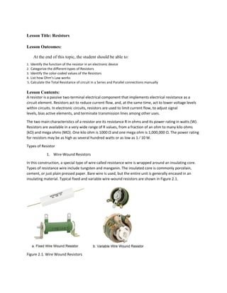
  • 1. Lesson Title: Resistors Lesson Outcomes: At the end of this topic, the student should be able to: 1. Identify the function of the resistor in an electronic device 2. Categorize the different types of Resistors 3. Identify the color-coded values of the Resistors 4. List how Ohm’s Law works 5. Calculate the Total Resistance of circuit in a Series and Parallel connections manually Lesson Contents: A resistor is a passive two-terminal electrical component that implements electrical resistance as a circuit element. Resistors act to reduce current flow, and, at the same time, act to lower voltage levels within circuits. In electronic circuits, resistors are used to limit current flow, to adjust signal levels, bias active elements, and terminate transmission lines among other uses. The two main characteristics of a resistor are its resistance R in ohms and its power rating in watts (W). Resistors are available in a very wide range of R values, from a fraction of an ohm to many kilo ohms (kΩ) and mega ohms (MΩ). One kilo ohm is 1000 Ω and one mega ohm is 1,000,000 Ω. The power rating for resistors may be as high as several hundred watts or as low as 1 ⁄ 10 W. Types of Resistor 1. Wire-Wound Resistors In this construction, a special type of wire called resistance wire is wrapped around an insulating core. Types of resistance wire include tungsten and manganin. The insulated core is commonly porcelain, cement, or just plain pressed paper. Bare wire is used, but the entire unit is generally encased in an insulating material. Typical fixed and variable wire-wound resistors are shown in Figure 2.1. Figure 2.1. Wire Wound Resistors
  • 2. Since they are generally used for high-current applications with low resistance and appreciable power, wire-wound resistors are available in wattage ratings from 1 W up to 100 W or more. The resistance can be less than 1 Ω up to several thousand ohms. For 2 W or less, carbon resistors are preferable because they are generally smaller and cost less. In addition, wire-wound resistors are used where accurate, stable resistance values are necessary. Examples are precision resistors for the function of an ammeter shunt or a precision potentiometer to adjust for an exact amount of resistance. 2. Carbon-Composition Resistors These resistors are made of finely divided carbon or graphite mixed with a powdered insulating material as a binder in the proportions needed for the desired resistance value. As shown in Figure 2.2 the resistor element is enclosed in a plastic case for insulation and mechanical strength. Joined to the two ends of the carbon resistance element are metal caps with leads of tinned copper wire for soldering the connections into a circuit. These are called axial leads because they come straight out from the ends. Carbon-composition resistors normally have a brown body and are cylindrical. Carbon-composition resistors are commonly available resistance values of 1 Ω to 20 M Ω. Examples are 10 Ω, 220 Ω, 4.7 k Ω, and 68 k Ω. The power rating is generally 1 ⁄ 10, 1 ⁄ 8, 1 ⁄ 4, 1 ⁄ 2, 1, or 2 W. Figure 2.2. Construction and Wattage of Carbon-Composition Resistors 3. Film-Type Resistors There are two kinds of film-type resistors: carbon-film and metal-film resistors. The carbon-film resistor, whose construction is shown in Fig. 2–4, is made by depositing a thin layer of carbon on an insulated
  • 3. substrate. The carbon film is then cut in the form of a spiral to form the resistive element. The resistance value is controlled by varying the proportion of carbon to insulator. Compared to carbon-composition resistors, carbon-film resistors have the following advantages: tighter tolerances, less sensitivity to temperature changes and aging, and they generate less noise internally. Metal-film resistors are constructed in a manner similar to the carbon-film type. However, in a metal- film resistor, a thin film of metal is sprayed onto a ceramic substrate and then cut in the form of a spiral. The construction of a metal-film resistor is shown in Fig. 2–5. The length, thickness, and width of the metal spiral determine the exact resistance value. Metal-film resistors offer more precise R values than carbon-film resistors. Like carbon-film resistors, metal-film resistors are affected very little by temperature changes and aging. They also generate very little noise internally. In overall performance, metal-film resistors are the best, carbon-film resistors are next, and carbon-composition resistors are last. Both carbon- and metal-film resistors can be distinguished from carbon-composition resistors by the fact that the diameter of the ends is a little larger than that of the body. Furthermore, metal-film resistors are almost always coated with a blue, light green, or red lacquer which provides electrical, mechanical, and climate protection. The body color of carbon-film resistors is usually tan. Figure 2.3. Construction of Film Type Resistors 4. Surface-Mount Resistors Surface-mount resistors, also called chip resistors, are constructed by depositing a thick carbon film on a ceramic base. The exact resistance value is determined by the composition of the carbon itself, as well as by the amount of trimming done to the carbon deposit. The resistance can vary from a fraction of an ohm to well over a million ohms. Power dissipation ratings are typically 1 ⁄ 8 to ¼ W. Figure 2.4 shows typical chip resistors. Electrical connection to the resistive element is made via two leadless solder end electrodes (terminals). The end electrodes are C-shaped. The physical dimensions of a 1 ⁄ 8 -W chip resistor are 0.125 in. long by 0.063 in. wide and approximately 0.028 in. thick. This is many times smaller than a conventional resistor having axial leads. Chip resistors are very temperature-stable and also very rugged. The end electrodes are soldered directly to the copper traces of a circuit board, hence the name surface-mount.
  • 4. 5. Fusible Resistors This type is a wire-wound resistor made to burn open easily when the power rating is exceeded. It then serves the dual functions of a fuse and a resistor to limit the current. Figure 2.5. Fusible Resistor 6. Thermistors A thermistor is a thermally sensitive resistor whose resistance value changes with changes in operating temperature. Because of the self-heating effect of current in a thermistor, the device changes resistance with changes in current. Thermistors, which are essentially semiconductors, exhibit either a positive temperature coefficient (PTC) or a negative temperature coefficient (NTC). If a thermistor has a PTC, its resistance increases as the operating temperature increases. Conversely, if a thermistor has an NTC, its resistance decreases as its operating temperature increases. How much the resistance changes with changes in operating temperature depends on the size and construction of the thermistor. Note that the resistance does not undergo instantaneous changes with changes in the operating temperature. A certain time interval, determined by the thermal mass (size) of the thermistor, is required for the resistance change. A thermistor with a small mass will change more rapidly than one with a large mass. Carbon- and metal-film resistors are different: their resistance does not change appreciably with changes in operating temperature.
  • 5. Figure 2.6.a. shows the standard schematic symbol for a thermistor. Notice the arrow through the resistor symbol and the letter T within the circle. The arrow indicates that the resistance is variable as the temperature T changes. As shown in Figure 2.6.b., thermistors are manufactured in a wide variety of shapes and sizes. The shapes include beads, rods, disks, and washers. Thermistors are frequently used in electronic circuits in which it is desired to provide temperature measurement, temperature control, and temperature compensation. Figure 2.6. Symbol and Types of Thermistor 7. Varistor Varistors are voltage-dependent resistors. This means that their resistance is dependent on the voltage across them.
  • 6. Figure 2.7. Varistor Reading the coded value The resistance value of a carbon resistor is color coded. There are four color bands printed on the body of a resistor. Each color represents a number. The color band which is closest to the left hand position of the resistor is the first color. An easy way to determine the first left hand color band is that of the color itself. The black color, for example, is not used for the first color or first digit. Gold and silver is for the third and fourth colors. When used as the third color it signifies the multiplier. The fourth color represents tolerance. The color coding is standardized by the Electronic Industries Alliance (EIA). See table below:
  • 7. Table 2.1. Color Equivalent Note: To determine the coded value of the resistor all you have to do is to write the first and second significant digit followed by the multiplier or number of zeroes that you are going to add after the second significant digit then write the unit and the percent of tolerance. Examples: 1. The value of a resistor is 10 ohms with a tolerance of 5%.Let us find out from the color code table what would be the color bands of the resistor in figure 1. Figure 2.8. 1st Example of reading resistance.
  • 8. The color that you have located in the table should match the colors in the first example. Continue checking with example number 2. 2. The value of the resistor is 100 ohms with a tolerance of 10%. Figure 2.9. 2nd Example of reading resistance Variable Resistors Variable resistors can be wire-wound or carbon type, illustrated in Figure 2.10.a. inside the metal case, the control has a circular disk, shown in Figure 2.10.b, that is the carbon-composition resistance element. It can be a thin coating on pressed paper or a molded carbon disk. Joined to the two ends are the external soldering-lug terminals 1 and 3. The middle terminal is connected to the variable arm that contacts the resistor element by a metal spring wiper. As the shaft of the control is turned, the variable arm moves the wiper to make contact at different points on the resistor element. The same idea applies to the slide control in Figure 2.11, except that the resistor element is straight instead of circular. When the contact moves closer to one end, the R decreases between this terminal and the variable arm. Between the two ends, however, R is not variable but always has the maximum resistance of the control. Carbon controls are available with a total R from 1000 Ω to 5 M Ω, approximately. Their power rating is usually 1 ⁄ 2 to 2 W.
  • 9. Figure 2.10. Construction of Variable Resistor Types of Variable Resistors 1. Tapered Controls The way R varies with shaft rotation is called the taper of the control. With a linear taper, a one-half rotation changes R by one-half the maximum value. Similarly, all values of R change in direct proportion to rotation. For a nonlinear taper, though, resistance can change more gradually at one end with bigger changes at the opposite end. This effect is accomplished by different densities of carbon in the resistance element. For a volume control, its audio taper allows smaller changes in resistance at low settings. Then it is easier to make changes without having the volume too loud or too low.
  • 10. Figure 2.11. Tapered Controls 2. Decade Resistance Box As shown in Figure 2.12, the decade resistance box is a convenient unit for providing any one R within a wide range of values. It can be considered test equipment for trying different R values in a circuit. Inside the box are six series strings of resistors, with one string for each dial switch. The first dial connects in an R of 0 to 9 Ω. It is the units or R x 1 dial. The second dial has units of 10 from 0 to 90 Ω. It is the tens or R x 10 dial. The hundreds or R x 100 dial has an R of 0 to 900 Ω. The thousands or R x 1 k dial has an R of 0 to 9000 Ω. The ten-thousands or R x 10 k dial provides R values of 0 to 90,000 Ω. The one-hundred-thousand or x 100 k dial provides R values of 0 to 900,000 Ω. The six dial sections are connected internally so that their values add to one another. Then any value from 0 to 999,999 Ω can be obtained. Note the exact values that are possible. As an example, when all six dials are on 2, the total R equals 2 + 20 + 200 + 2000 + 20,000 + 200,000 + 222,222 Ω. Figure 2.12. Decade Resistance Box 3. Rheostats and Potentiometers Rheostats and potentiometers are variable resistances, either carbon or wire-wound, used to vary the amount of current or voltage in a circuit. The controls can be used in either dc or ac applications.
  • 11. A rheostat is a variable R with two terminals connected in series with a load. The purpose is to vary the amount of current. A potentiometer, generally called a pot for short, has three terminals. The fixed maximum R across the two ends is connected across a voltage source. Then the variable arm is used to vary the voltage division between the center terminal and the ends. A potentiometer can act as a rheostat by connecting one end of the control and the variable arm, using only two terminals. The third terminal is open, or floating, not connected to anything. Another method is to wire the unused terminal to the center terminal. When the variable arm is rotated, different amounts of resistance are short-circuited. This method is preferable because there is no floating resistance. Figure 2.13. Rheostats and Potentiometers Series and Parallel Combinations of Resistors  Resistor Connection: There are three common methods of connecting resistors together. These connections are series, parallel and series parallel. Series: In series connection two or more resistors are tied together like a chain. The individual resistances are added up for the total resistance. For example, there are three resistors connected in series. Each resistor has a resistance of 10 ohms (Figure 2.14).
  • 12. Figure 2.14. Series Connection The formula for series resistance will be: Rt = R1 + R2 + R3 where Rt is the total resistance and R1, R2, R3 represent individual resistances. In this example the total resistance is computed as Rt = 10 + 10 + 10 = 30 ohms. The power or wattage of each resistor connected in series is similarly added for the total wattage. For example, we have two resistors connected in series and each resistor is ½ watt. The total wattage of the two will be 1 watt. Parallel: In parallel connection two or more resistors are connected as shown in Figure 2.14. In this method of connection the individual resistances are not added. Simplifying solutions for determining the total resistance of parallel resistors we can adopt the following method. If two or more resistors with the same values are in parallel simply divide the value of one resistor by the number of resistors. If there are two resistors of unequaled values connected in parallel the total resistance is smaller than the lowest value of an individual resistor in the circuit. The formula is: Rt = multiply 2 values / add 2 values
  • 13. When there are three or more resistors of different values in parallel the formula will be: Instead of solving though the reciprocal formula the total resistance of a parallel connection can be calculated through the mentioned earlier formula of product over sum. The solution will be longer, however, the end result will be the same. First, compute for the total resistance of two resistors. After that take the total resistance of the first two, considered as one, and compute with another resistor which is in parallel with the first two. Having arrived at the total resistance of the three resistors you can go on computing for any additional number of resistors using the same method. Note: In the case of series connection, the combined resistance value increases as the number of resistors in the connection becomes large and decreases in parallel connection as the number of resistors in the connection increases. Series Parallel Connection In practice, there are instances when resistors have no exact replacements available. Depending on the available values on hand a series parallel substitution can be installed. A series parallel circuit is a combination of two or more circuits in parallel with each circuit being a series connection. An example of series parallel connection is shown in figure 8. R1 and R2 are in series connection; R3 and R4 are also series. By joining the two series connections into a parallel connection a series parallel connection is formed. To solve for Rt: R1 and R2 are connected in series, so let’s assume Ra = R1 + R2
  • 14. R3 and R4 are also connected in series, then Rb = R3 + R4 Rt = Ra Rb / Ra +Rb , we use this formula because Ra and Rb are connected in parallel In any case of resistor replacement whether it is single, series or parallel the value of a new resistor or a total value of a group of resistors should be equal or very close to the original resistor. The original wattage of the resistor to be replaced should also be taken into consideration and matched closely. For example, do not replace a 5-watt resistor with another one of, say, 1 watt. The same is true with a small wattage resistor being replaced by a larger one. This will result in a shorter life if not in an instant damage. The wattage of a resistor does not affect or alter its resistance value but it certainly affects its performance if wattage is not properly chosen. Ohm’s Law Before we proceed with ohm’s law let us refresh our mind first with the basic electricity. All the materials we know, including solids, liquids, and gases, contain two basic particles of electric charge: the electron and the proton. An electron is the smallest amount of electric charge having the characteristic called negative polarity. The proton is a basic particle with positive polarity. The negative and positive polarities indicate two opposite characteristics that seem to be fundamental in all physical applications. Just as magnets have north and south poles, electric charges have the opposite polarities labeled negative and positive. The opposing characteristics provide a method of balancing one against the other to explain different physical effects. It is the arrangement of electrons and protons as basic particles of electricity that determines the electrical characteristics of all substances. As an example, this paper has electrons and protons in it. There is no evidence of electricity, though, because the number of electrons equals the number of protons. In that case, the opposite electrical forces cancel, making the paper electrically neutral. The neutral condition means that opposing forces are exactly balanced, without any net effect either way. When electrons can move easily from atom to atom in a material, the material is a conductor. In general, all metals are good conductors, with silver the best and copper second. Copper wire is generally used for practical conductors because it costs much less than silver. The purpose of using conductors is to allow electric current to flow with minimum opposition. The wire conductor is used only to deliver current produced by the voltage source to a device that needs the current to function. As an example, a bulb lights only when current flows through the filament.
  • 15. A material with atoms in which the electrons tend to stay in their own orbits is an insulator because it cannot conduct electricity very easily. However, insulators can hold or store electricity better than conductors. An insulating material, such as glass, plastic, rubber, paper, air, or mica, is also called a dielectric, meaning it can store electric charge. Insulators can be useful when it is necessary to prevent current fl ow. In addition, for applications requiring the storage of electric charge, as in capacitors, a dielectric material must be used because a good conductor cannot store any charge. Carbon can be considered a semiconductor, conducting less than metal conductors but more than insulators. In the same group are germanium and silicon, which are commonly used for transistors and other semiconductor components. Practically all transistors are made of silicon. Electric charge is the physical property of matter that causes it to experience a force when placed in an electromagnetic field. There are two types of electric charges: positive and negative. Positively charged substances are repelled from other positively charged substances, but attracted to negatively charged substances; negatively charged substances are repelled from negative and attracted to positive. An object is negatively charged if it has an excess of electrons, and is otherwise positively charged or uncharged. The coulomb (unit symbol: C) is the International System of Units (SI) unit of electric charge. It is the charge (symbol: Q or q) transported by a constant current of one ampere in one second. It is named after Charles-Augustin de Coulomb a French Physicist. An electric current is a flow of electric charge. In electric circuits this charge is often carried by moving electrons in a wire. It can also be carried by ions in an electrolyte, or by both ions and electrons. The ampere (SI unit symbol: A), is the unit of electric current. It is named after André-Marie Ampère (1775–1836), French mathematician and physicist, considered the father of electrodynamics. Amperes are used to express flow rate of electric charge. Voltage, electric potential difference, electric pressure or electric tension is the difference in electric potential energy between two points per unit electric charge. The voltage between two points is equal to the work done per unit of charge against a static electric field to move the charge between two points and is measured in units of volts (a joule per coulomb). The volt (symbol: V) is the derived unit for electric potential, electric potential difference (voltage), and electromotive force. The volt is named in honor of the Italian physicist Alessandro Volta (1745– 1827), who invented the voltaic pile, possibly the first chemical battery. Resistance is the opposition that a substance offers to the flow of electric current. It is represented by the uppercase letter R. The ohm (symbol: Ω) is the unit of electrical resistance, named after German physicist Georg Simon Ohm. Now that we already have the knowledge of basic electricity we are now ready to face the Ohm’s Law.
  • 16. The relationship between voltage, current, and resistance was discovered in 1826 by Georg Simon Ohm. The relationship, known as Ohm’s law, is the basic foundation for all circuit analysis in electronics. Ohm’s law, which isthe basis of this chapter, states that the amount of current, I, is directly proportional to the voltage, V, and inversely proportional to the resistance, R. Expressed mathematically, Ohm’s law is stated as I = V/R Electric power is the rate at which electrical energy is transferred by an electric circuit. It is usually produced by electric generators, but can also be supplied by sources such as electric batteries. It is generally supplied to businesses and homes by the electric power industry through an electric power grid Electric power is the rate of doing work, measured in watts, and represented by the letter P. The term wattage is used colloquially to mean "electric power in watts." The electric power in watts produced by an electric current I consisting of a charge of Q coulombs every t seconds passing through an electric potential (voltage) difference of V is Where: Q is electric charge in coulombs t is time in seconds I is electric current in amperes V is electric potential or voltage in volts Series and Parallel Circuit Analysis General Methods for Series Circuits For other types of problems with series circuits, it is useful to remember the following: 1. When you know the current (I) for one component, use this value for I in all components, for the current is the same in all parts of a series circuit. 2. To calculate current (I), the total VT can be divided by the total RT, or an individual IR drop can be divided by its R. However, do not mix a total value for the entire circuit with an individual value for only part of the circuit. 3. When you know the individual voltage drops around the circuit, these can be added to equal the applied VT. This also means that a known voltage drop can be subtracted from the total VT to find the remaining voltage drop. Example number 1:
  • 17. Find the resistance of R3. Figure 2.20. Series Circuit for Example 1 These principles are illustrated by the problem in Fig. 4–13. In this circuit, R1 and R2 are known but not R3. However, the current through R3 is given as 3 mA. With just this information, all values in this circuit can be calculated. The current (I) of 3 mA is the same in all three series resistances. Therefore, V1 = 3 mA x 10 k Ω = 30 V V2 = 3 mA x 30 k Ω = 90 V The sum of V1 and V2 is 30 + 90 = 120 V. This 120 V plus V3 must total 180 V. Therefore, V3 is 180 - 120 = 60 V. With 60 V for V3, equal to IR3, then R3 must be 60/0.003, equal to 20,000 Ω or 20 kΩ. The total circuit resistance is 60 kΩ, which results in the current of 3 mA with 180 V applied, as specified in the circuit. Another way of doing this problem is to find RT first. The equation I = V T / R T can be inverted to calculate R T. R T =VT/I With a 3-mA I and 180 V for VT, the value of RT must be 180 V/3 mA = 60 kΩ. Then R3 is 60 kΩ - 40 kΩ = 20 kΩ. The power needed to produce current in each series resistor is used up in the form of heat. Therefore, the total power used is the sum of the individual values of power dissipated in each part of the circuit. As a formula, PT = P1 + P 2 + P 3 + · · · + etc. The power dissipated in each resistance is 90 mW in R1, 270 mW in R2, and 180 mW in R3. The total power is 90 + 270 + 180 = 540 mW. Analyzing Parallel Circuits For many types of problems with parallel circuits, it is useful to remember the following points.
  • 18. 1. When you know the voltage across one branch, this voltage is across all the branches. There can be only one voltage across branch points with the same potential difference. 2. If you know IT and one of the branch currents I1, you can find I2 by subtracting I1 from I T. Example Number 2: Figure 2.21. Parallel Circuit for Example Number 2 The circuit in Figure 2.21 illustrates these points. The problem is to find the applied voltage VA and the value of R3. Of the three branch resistances, only R1 and R2 are known. However, since I2 is given as 2A, the I2 R2 voltage must be 2 x 60 = 120 V. Although the applied voltage is not given, this must also be 120 V. The voltage across all the parallel branches is the same 120 V that is across the R2 branch. Now I1 can be calculated as VA /R 1. This is 120/30 = 4 A for I1. Current IT is given as 7A. The two branches take 2 + 4 = 6 A. The third branch current through R3 must be 7 - 6 = 1 A for I3. Now R3 can be calculated as VA /I3. This is 120/1 = 120 Ω for R3 Total Power in Parallel Circuits Since the power dissipated in the branch resistances must come from the voltage source, the total power equals the sum of the individual values of power in each branch. Note also that in both parallel and series circuits, the sum of the individual values of power dissipated in the circuit equals the total power generated by the source. This can be stated as a formula PT = P 1 + P 2 + P 3 + . . . + etc. The series or parallel connections can alter the distribution of voltage or current, but power is the rate at which energy is supplied. The circuit arrangement cannot change the fact that all the energy in the circuit comes from the source. In a circuit the total power can be solve using the formula PT = VT x IT or by adding the individual values of power.
  • 19. PT = 120V x 7A = 840 W Or PT = P1 + P2 + P3 P1 = VT x I1 = 120V x 4A = 480 W P2 = VT x I2 = 120V x 2A = 240 W P2 = VT x I2 = 120V x 1A = 120 W therefore, PT = 480 + 240 + 120 = 840W Series Circuit Parallel Circuit Current is the same in all components Voltage is the same across all branches V across each series resistance is I X R I in each branch is V / R VT = V1 + V2 + V3 + … + etc. IT = I1 + I2 + I3 + … + etc. RT = R1 + R2 + R3 + … + etc. 1/RT = 1/R1 + 1/R2 + 1/R3 + … + etc. RT must be more than the largest individual R RT must be less than the smallest branch R P1 = P1 + P2 + P3 + … + etc. P1 = P1 + P2 + P3 + … + etc. Applied voltage is divided into IR voltage drop Main-line current is divided into branch current The largest IR drop is across the largest series R The largest branch I is in the smallest parallel R Open in one component causes entire circuit to be open Open in one branch does not prevent I in other branches Table 2.2. Series Circuit vs. Parallel Circuit Analyzing Series-Parallel Circuits with Random Unknowns The following principles are illustrated: 1. With parallel strings across the main line, the branch currents and IT can be found without RT. 2. When parallel strings have series resistance in the main line, RT must be calculated to find IT, assuming no branch currents are known. 3. The source voltage is applied across the R T of the entire circuit, producing an IT that flows only in the main line. 4. Any individual series R has its own IR drop that must be less than the total VT. In addition, any individual branch current must be less than IT. Example Number 3. Find all currents and voltages in Figure 2.22.
  • 20. Figure 2.22. Circuit for Example Number 3 Solution for Figure 2.22. The problem here is to calculate the branch currents I1 andI2–3, total line current IT, and the voltage drops V1, V2, and V3. This order will be used for the calculations because we can find the branch currents from the 90 V across the known branch resistances. In the 30Ω branch of R1, the branch current is 90/30 = 3 A for I1. The other branch resistance, with a 20Ω R2 and a 25Ω R3, totals 45 Ω. This branch current then is 90/45 = 2 A for I2–3. In the main line, IT is 3 A + 2 A, which is equal to 5 A. For the branch voltages, V1 must be the same as VA, equal to 90 V, or V1 = I1 R1, which is 3 x 30 = 90V. In the other branch, the 2A I2–3 flows through the 20Ω R 2 and the 25Ω R3. Therefore, V2 is 2 x 20 = 40 V. Also, V3 is 2 x 25 = 50 V. Note that these 40V and 50V series IR drops in one branch add to equal the 90V source. If we want to know RT, it can be calculated as VA / IT. Then 90 V/5 A equals 18 Ω. Or RT can be calculated by combining the branch resistances of 30 Ω in parallel with 45 Ω. Then, using the product-divided-by- sum formula, R T is (30 x 45) / (30 + 45) or 1350/75, which equals the same value of 18 Ω for RT. Example Number 4. Find VA, V4 and R4 from I2 and the branch voltages in Figure 2.23.
  • 21. Figure 2.23. Circuit for Example Number 4 Solution for Figure 2.23. To find the applied voltage first, the I1 branch current is given. This 3A current through the 10Ω R1 produces a 30V drop V1 across R1. The same 3A current through the 20Ω R2 produces 60 V for V2 across R2. The 30V and 60V drops are in series with each other across the applied voltage. Therefore, VA equals the sum of 30 + 60, or 90 V. This 90 V is also across the other branch combining R3 and R4 in series. The other branch current I2 in Fig. 6–7 must be 4A, equal to the 7A IT minus the 3A I1. With 4A for I2, the voltage drop across the 12Ω R3 equals 48 V for V3. Then the voltage across R4 is 90 - 48, or 42 V for V4, as the sum of V3 and V4 must equal the applied 90 V. Finally, with 42 V across R4 and 4A through it, this resistance equals 42/4, or 10.5 Ω. Note that 10.5 Ω for R4 added to the 12Ω of R3 equals 22.5 Ω, which allows 90/22.5 or a 4A branch current for I2. Example Number 5. Find R2 and I2 in Figure 2.24.
  • 22. Figure 2.24. Circuit for Example Number 5 Solution for Figure 6–8 The division of branch currents also applies to Fig. 6–8, but the main principle here is that the voltage must be the same across R1 and R2 in parallel. For the branch currents, I2 is 2A, equal to the 6A IT minus the 4A I1. The voltage across the 10Ω R1 is 4 x 10, or 40 V. This same voltage is also across R 2. With 40 V across R2 and 2A through it, R2 equals 40/2 or 20 Ω. We can also find VT in Fig. 6–8 from R1, R2, and R3. The 6A IT through R3 produces a voltage drop of 60V for V3. Also, the voltage across the parallel bank with R1 and R2 has been calculated as 40 V. This 40 V across the bank in series with 60 V across R3 totals 100 V for the applied voltage. References: Malcom Plant. Electronics Malvin and Brown. Digital Computer Electronics, 3 rd Ed Teaching Delivery (TLAs)  Lecture– online  Question-Answer Method - online Assessment:  Quiz –face to face / online
  • 23.  Assignment- Modular o Rubric to be used in checking student’s assignment. Points 5 4 3 2 1 Original Ideas (5 pts) Interesting content with correct perspective and completely discusses what was asked. Communicates Information well and discusses what was asked. Basic information is Conveyed from what was asked in the essay. Ideas are below the expected level. No thought given to the Content. Organization (3 pts) Sentences flow together Well. Well understood sentences and the meanings are clearly laid out. Occasional awkward Sentences. A number of awkward Sentences. Many sentences are hard to understand. Timeliness (2 pts) The assignment was submitted on or before the deadline. The assignment was submitted 1- 2 days after the deadline. The assignment was submitted 3- 4 days after the deadline. The assignment was submitted 5- 6 days after the deadline The assignment was submitted a week after the deadline  For assignment with computation Points 4 3 2 1 Understanding the Problem 5 pts) Identified special factors that influenced the approach before starting the problem. Understood the problem. Understood enough to solve part of the problem or to get part of the solution. Didn't understand enough to get started or make progress. How Student Solved Problem (4 pts) Well understood sentences and the meanings are clearly laid out. Approach was efficient or sophisticated. Approach would only lead to solving part of the problem. Approach didn't work. Outcomes of Activities(4) Solved the problem and made general rule about the solution or extended the solution to a more complicated situation. Solved the problem and described a use for what was learned in the "real world." Only partly correct reasoning, or correct reasoning used for only part of the problem. Solved the problem and stopped. Timeliness (2 pts) The assignment was submitted 1-2 days after the deadline. The assignment was submitted 3- 4 days after the deadline. The assignment was submitted 5-6 days after the deadline The assignment was submitted a week after the deadline