SlideShare a Scribd company logo
1 of 31
Download to read offline
www.infomaticaacademy.com XI - SCIENCE Email : info@infomaticaacademy.com
ELECTRONIC COMPONENTS 39
il.com
CLASSIFICATION OF COMPONENTS
(a) Passive Components
Since this category belongs to inactive functions of the component, these
components do not have capacity to amplify the voltage or to rectify supply
therefore, they are called as “Passive components”. Resistors, capacitors and
Inductors are called as passive components.
(b) Active Components
Since these components are capable of performing active functions like
amplification, rectification and switching, they are called as “active
components”.
(i) Electron tubes like Diode, triode and (ii) Semiconductor devices like diode,
LED, Transistor etc.Electron tubes are rarely used because they are outdated.
RESISTORS
The value of resistance is measured in Ohm (  ). Resistance is the opposition to the
flow of electrons or simply opposition to the electric current. Resistance is required
in electronic circuits to limit the current, to drop the voltage and to divide the
voltage. In combination with capacitor, it is used as filter or it can be used to
achieve a time delay.
ELECTRONIC COMPONENTS
www.infomaticaacademy.com XI - SCIENCE Email : info@infomaticaacademy.com
ELECTRONIC COMPONENTS 40
 Types Of Resistors
Resistors may be classified as (a) Fixed Resistors and (b) Variable Resistors.
(A) Fixed Resistors
Fixed resistors can be classified into three types according to the material used
(1) Carbon types  (a) Carbon composition type, (b) Carbon film type.
(2) Wire wound type
(3) Metal film type
(1) Carbon Composition Resistors
These resistors are widely used in electronic circuits. Carbon composition
resistor‟s value is available from 1 to about 20 M and typical power
ratings are 1/5 W to 2W. Speciality of these resistors is low cost and small
size. (Most of the resistors available in your laboratory are carbon
composition type.). These resistorsare manufactured by mixing granules of
carbon with binding material. This cylinder is molded in a cylindrical form
as shown. Fig. (4.3) shows the construction and different wattages of
resistors. Tinned copper wire leads are inserted in the two ends and
structure is sealed with non-conducting coating. The cost of resistor
depends on its wattage and not on the value of resistor.
www.infomaticaacademy.com XI - SCIENCE Email : info@infomaticaacademy.com
ELECTRONIC COMPONENTS 41
 Colour coding of Carbon Resistor
Method: In colour code method, the first two rings indicate the first two digits
and the third ring indicates the multiplier. Fourth ring is used to indicate its
tolerance.
 Colour Code Chart
Colour Value of the 1st
and 2nd ring
Value of 3rd ring
(Multiplier )
Tolerance
Black 0 X 0
10
Brown 1 X 1
10 ±1%
Red 2 X 2
10
Orange 3 X 3
10
Yellow 4 X 4
10
Green 5 X 5
10
Blue 6 X 6
10
Violet 7 X 7
10
Gray 8 X 8
10
White or No
Colour
9 X 9
10 ±20%
Gold - X -1
10 ±5%
Silver - X -2
10 ±10%
EXAMPLES
Find the value of carbon resistors by using colour code method.
2
)Re , ,Re
2 7 10 5%
27 100 2700 2.7 2 7
i d Violet d gold
X
X K or K

    
3
) , ,
1 0 10 10%
10 1000 10,000 10
ii Brown Black Orange Silver
X
X K

    
www.infomaticaacademy.com XI - SCIENCE Email : info@infomaticaacademy.com
ELECTRONIC COMPONENTS 42
1
)Re ,Re ,
2 2 10 5%
22 10 2.2
iii d d Gold Gold
X 

   
4
) , ,
5 0 10 10%
50 10000 500,000 500 0.5
iv Green Black Yellow Silver
X
x K M

      
(2) Carbon film Resistors
This is another variety of carbon resistors in which a thin film of carbon is
deposited on an insulating material like ceramic rod. During the deposition
of the film, the value of resistance is adjusted by controlling the groove
length and width of carbon film ribbon.
Speciality: Low cost, Precision type.
Range: 10 to10 M , Power rating upto 2W.
(3) Wire Wound Resistors
Wire wound resistor is used where high current control is required as well
as where stable and accurate value of resistor is required. A wire wound
resistor is manufactured by wrapping a length of special resistive wire like
nichrome or mangenin around an insulating core of ceramic. The end of
wire is attached to metal contacts,which are inserted in the core. After wire
is wound, the whole structure is coated with enamel containing powdered
glass and then heated to produce coating, this is known as vitreous enamel
coating. It I required to protect the resistor and to dissipate the heat.
Typical values are available in fraction of ohms to 100 K  . Power rating is
from 5 W to 200 W.
Speciality : Big in size, more power handling capacity. Colour code system is
not used due to its big size. Ohm value is directly specified on the
resistor.
Range : Fraction of  to 100 100 K  and power rating 5 W TO 200 W.
www.infomaticaacademy.com XI - SCIENCE Email : info@infomaticaacademy.com
ELECTRONIC COMPONENTS 43
COMPARISON
Carbon Composition Resistor Wire Wound Resistor
1. Carbon granules are used. A resistive wire like nichrome is used.
2. Tolerance is 2% to 20% More precision type because tolerance is
very low.
3. Wide range of resistance. Available in low values only.
4. Low power ratings. High power ratings.
5. Color code system is used. No color code system is used.
6. Small size and low cost. Big size and high cost.
(4) Metal Film Resistor ( MFR)
These resistors are used for accurate value (precision type) because its
tolerance is lessthan 5% . These resistors are manufactured in similar way
to that of carbon film. Metal film of metal oxide or metal alloy is coated on a
ceramic rod. There are different types of metal film like
(1) Thin Film – Film layer is thin
(2) Thick Film – Film layer is thick.
Speciality : Low noise, good stability and tolerance less than 0.5%
Range : 10 to 1 M.
(B) VARIABLE RESISTORS
Variable resistors are commonly called as rheostats. In low current circuit like in
electronic circuit, small variable resistors are called as “potentiometer of pots”.
Variable resistors are normally used in radio or audio equipment for volume
control, and contrast and brightness control in TV sets. According to material
used these resistors are classified into two types
(1) Carbon type and (2) Wire wound type
(1) Carbon Type Potentiometers
Basically the construction of all potentiometers is same. In this type a
movable metal pointer known as a „wiper‟ moves on a circular carbon
resistive track as shown in fig. (4.6) this wiper is attached to a shift it may
be metal or a plastic shaft.
www.infomaticaacademy.com XI - SCIENCE Email : info@infomaticaacademy.com
ELECTRONIC COMPONENTS 44
Variable resistors always have three terminals as shown, terminal 1 and 3
are fixed terminals and 2 is variable terminal. When terminal 1 and 3 are
connected in the circuit you will get fixed and maximum resistance. When 1
and 2 or 2 and 3 terminals are connected you will get variation in resistance
when you rotate the shaft.
If you connect terminal 1 and 2 at extreme left side wiper will be at terminal
1, hence you will get zero resistance and when you rotate towards the right
side its resistance increases.
These variable resistors are available in two types,
(1) Linear Type (2) Log Type.
In linear potentiometer resistance varies with linear rate. If you rotate the
shaft suppose for 0
10 rotation it gives 100 at 0
20  20 and so on. But in
nonlinear potentiometer (log type) resistance varies in log scale, at
0 0 0
10 10 ,20 100 30 1000     .
When the maximum range of resistance is required „Log type‟ pot is
preferred.
When often variation of resistance is required these carbon potentiometers
are used like volume control but when rare adjustment is required small
potentiometer called as “presets” are used. A power ON/OFF switch is
commonly used with thee pots V/C with ON/OFF. Sometimes two or more
resistor variation is required in synchronization. This type of potentiometer
is called as “Gang pot”.
www.infomaticaacademy.com XI - SCIENCE Email : info@infomaticaacademy.com
ELECTRONIC COMPONENTS 45
Speciality: Low cost, Used in Radio, TV as volume control, brightness
control etc.
Range: 1K to 5 M, Power rating 1/2W to 2W.
(2) Wire Wound Potentiometers:
Basic principle of construction of wire wound variable resistor is simple; the
most common example of this type is rheostat. In this type is wound on an
open ring of ceramic, which is covered with vitreous enamel.
The speciality of such type is high power handling capacity and very small
and accurate change of resistance. Figure shows the constructions of wire
wound pot and rheostat. In wire wound variable resistor non- linear resistor
is also available (tapered type). Non-linearity in the resistor is achieved by
using tapered stripon which resistive wire is wound fig… shows linear and
non- linear potentiometer. By sliding the contact, the variation of resistance
is achieved.
Speciality: High Cost, Most power handling capacity, big size.
Range: 100K to 1 M, Power rating 2W to 100 W.
www.infomaticaacademy.com XI - SCIENCE Email : info@infomaticaacademy.com
ELECTRONIC COMPONENTS 46
(C) OTHER RESISTORS
Because of large development in semiconductor technology in addition to diode
and transistors;special type of resistorsare manufactured which may be called
as active resistors.
(1) Thermistor
A Thermistor is a semiconductor device whose resistance varies with
temperature but change resistance is non-linear. Conductors show very
small change in resistance but thermistor increase or decrease its resistance
by more value. Hence thermistor can be NTC or PTC type. When resistance
decreases with increase in temperature then then it is called as “Negative
Temperature Coefficient” of resistance (NTC) and it is increases then it is
called as “positive Temperature Coefficient” of resistance (PTC). Thermistors
are used in many applications like measurement of temperature,
temperature control, temperature compensation etc.
(2) Light Dependent Resistor (LDR)
It is a photosensitive device whose resistance decreases with increase in
light intensity. The symbol is shown in fig. Cadmium sulfide material is used
for this purpose. It‟s dark resistance is about 100K  and it decreases with
increase in light. LDR is widely used in many application like automatic
street light control, burglar alarm etc.
(3) Varistor (VDR)
It is also a non- linear resistor in which resistance is made variable to
voltage. It is also known as voltage dependent resistor. They are two types.
(i) Silicon Carbide VDR, (ii) Metal Oxide VDR. Varistor are used in industrial
application and TV circuits to surge suppression.
www.infomaticaacademy.com XI - SCIENCE Email : info@infomaticaacademy.com
ELECTRONIC COMPONENTS 47
CAPACITORS
Capacitor is second important passive component, commonly observed in electronic
circuits.Many times it is called as condenser. Basically it is used to store electrical
energy (by charging) and to deliver this stored energy (by discharging). This
component has specific capacity of storing charge across it, hence named as
capacitors. They are available in fixed and variable types; their capacity is measured
in „farad‟. They are available in typical range of picofarads to microfarads. A
capacitor consists of two parallel conducting surfaces separated by an insulator
called as dielectric material. Different symbols of capacitor are shown in the fig...
A capacitor is formed by two parallel conducting plates (may be spherical in
structure) Separated by an insulating material.Insulating material like mica, paper,
and ceramic called as “dielectric”. In electronic circuits capacitors plays an
important role like resistor,it has got many applications such as in photo camera for
flash, in power supplies used as a filter, in amplifiers as a coupling or a bypass
capacitor and so on. Let us see its action of charging and discharging.
As shown in the fig... When battery is connected across the capacitor, current flows
through the circuit; current meter is connected for the indication.Before connecting
the battery the number of electronson plate A and B are equal but when battery is
connected across it, electronsare accumulated on plate A because they cannot flow
www.infomaticaacademy.com XI - SCIENCE Email : info@infomaticaacademy.com
ELECTRONIC COMPONENTS 48
through dielectric. An electrostatic force is developed by the plate A that gives a
pressure to plate B. It passes the same number of electrons towards the battery.
This is known as electrostatic induction. Thus we get negative charge on the plate A
and positive on the plate B that produces a potential difference. Electrons continue
to flow till voltage across capacitor becomes the battery voltage.Shows how capacitor
voltage increases towardsbattery voltage and it shows current through it. Observe
the graph when voltage across capacitor is „V‟ current is zero the process of charging
is stopped. Remember, initially current is maximum and then it slowly decreases to
zero.
Formulae: (a) Capacitors in Series
s 1 2 3
1 1 1 1
.......
C C C C
   
(b) Capacitors in Parallel
1 2 3 ....pC C C C   
Example:
1) Two capacitors 20 μf and 5μf are connected in series and then connected in
parallel the effective capacitance in each case.
Solution
In series In parallel
1 2
3 1 2 1 2
C C1 1 1 20 5
4μf
C C C C +C 25

    
1 2 20 5 25μfpC C C    
www.infomaticaacademy.com XI - SCIENCE Email : info@infomaticaacademy.com
ELECTRONIC COMPONENTS 49
2) A capacitor of 0.2μf is connected in series with a resistance of 15MΩ. Find the
time constant and the time required to charge up to battery voltage is 10V. What
is the voltage across capacitor at 1 time constant?
Solution
6 6
15 10 0.2 10 3sec.T R xc x 
          
After 3 sec. the voltage acrosscapacitor is 63.2% of battery voltage i.e. 6.3 volts.
It takes 3x 5 =15 seconds to charge up to 10 volts.
TYPE OF CAPACITORS
A) Fixed Capacitors
Fixed capacitors can be classified according to the dielectric material and polar/
nonpolar such as,
(i) Paper capacitor Non polar capacitor
(ii) Mica capacitor Non polar capacitor
(iii) Polyester capacitor Non polar capacitor
(iv) Ceramic capacitor Non polar capacitor
(v) Aluminium electric capacitorpolar capacitor
(vi) Tantalum electric capacitorpolar capacitor
(1) Paper Capacitors
Basically the construction for all fixed non-polar capacitors is same. Two
conducting surfaces are separated by electric material. Paper capacitor is
manufactured by rolling two thin metal foils (foil is a long strip of metal)
separated by a paper roll as shown in fig. Paper used for this purpose is
Kraft paper impregnated with wax or resinor oil. Where, impregnation is the
process in which paper is soaked with dielectric wax or oil.
www.infomaticaacademy.com XI - SCIENCE Email : info@infomaticaacademy.com
ELECTRONIC COMPONENTS 50
Speciality: Medium range of capacitance, small size and non- polar.
Typical range: 500pF to 1μf and typically voltage rating from 100 V to 1000 V.
(2) Mica Capacitors
The construction is similar to that of paper capacitor only the die lectric
material used is mica foil or mica sheet as shown.
Mica capacitors are square or rectangular in shape with timed with leads.
The entire structure is molded in Bakelite sheet.
Speciality: High temperature range - o o
55 C to ±150 C Non- polar.
Typical range: 5pF to 10,000 pF Voltage rating about 500V.
(3) Ceramic Capacitor
These capacitors are commonly observed in many circuits like amplifier,
oscillators etc, as coupling capacitor. They are available in many different
shapes like disc type, rectangular type, tabular and button type as shown in
fig.
The construction of ceramic capacitor is different than paper and mica
capacitor. It is constructed by depositing silver plates on each side of a very
thin of ceramic material.During the process tinned wire leads are attached
to each plate. In this type colour code system is used but now values are
directly printed on capacitor. It is also a non- polar capacitor.
Speciality: Most economical in price 1 Rs. Per piece.
Typical range: 3pF to 2 μF and voltage range from 3V to 6000 Volts non-polar.
www.infomaticaacademy.com XI - SCIENCE Email : info@infomaticaacademy.com
ELECTRONIC COMPONENTS 51
(4) Aluminium Electrolytic Capacitor
This is a polar capacitor on which polarities are marked as positive and
negative. Polarity is important because reverse connection may damage the
capacitor. Another main difference between non- polar and polar; these
capacitors are manufactured in higher values. Higher values are possible
because electrolyte is used to provide more capacitance in smallest space.
Electrolyticcapacitor consistsof Aluminium foil electrode as an aluminium
oxide film covering one side and is in contact with an electron conducting
fluid known as an electrolyte. The Aluminium oxide forms a dielectricand the
electrolyte form another plate of capacitor. A layer of plain Aluminium foil is
also wound into the capacitor to provide electrical contact betweenone of the
terminals and electrolyte.
(5) Tantalum Capacitors
This is another type of electrolytic polar capacitor in which tantalum is used
instead of aluminium.The construction is quite similar.The main advantage
of tantalum is log shelf life, stable operation and greater temperature range.
Disadvantages are high cost and low operating voltage.
B) Variable Capacitors
There is a need of variable capacitor in various circuits like tuning circuit of
radio, oscillator circuit to vary the frequency etc.
(1) Air Gang Capacitor
Air gang condenser is a common example of variable capacitor. Other
variable capacitors are similar to variable condenser but they are adjustable
known as trimmers and padders. Gang condenser consists of two sets of
parallel plates. One of the sets is fixed called as stator and another set is
called as rotor. This rotor set of parallel plates is fitted on a movable shaft.
When the shaft is rotated the area covered by each plate of rotor and stator
www.infomaticaacademy.com XI - SCIENCE Email : info@infomaticaacademy.com
ELECTRONIC COMPONENTS 52
is varied and thus total capacitance is varied. In valve type old ratio circuit
two gang capacitors are used while in transistor receiver miniature type is
used. Fig. shows simple construction of air gang capacitor.
(2) Trimmers and Padders
Since they are used for line tunning, they are constructed on the gang
condenser itself they are called as trimmers and padders. Basically these are
small variable capacitorsusing air, mica, ceramic as dielectric; some of the
constructions are shown in fig.
A screwdriver can be used to adjust the capacitance value. When rare
variation of capacitance is required these capacitors are used.
INDUCTORS
Inductor is a third important passive component widely used in AC circuitsthan DC.
Inductor is a simple coil of copper wound on a core material.
Inductance is the ability of a conductor to produce an induced voltage,when current
through it varies. In other words inductor opposes change in current.
The unit of inductance is “Henry”. It is defined as the inductance that will develop a
voltage of one volt across it when current changes at the rate of one Ampere per
second or when a voltage of one volt is induced for the change of current rate 1
Amp/ Sec then the inductance of coil is said to be 1 Henry.
INDUCTANCE
It is the property of conductor to produce induced voltage, when current through it
varies. Induced voltage is the result of change of flux across a conductor because
when AC current flows through it magnetic flux varies its strength and the direction,
which is equivalent to motion of the flux. When DC current flows through the
conductor voltage induction is not possible induction is not possible because DC
www.infomaticaacademy.com XI - SCIENCE Email : info@infomaticaacademy.com
ELECTRONIC COMPONENTS 53
current is steady and it flows only in one direction. Inductor behaves like a
conducting wire on DC.
 Types Of Inductors
Inductors can be classified into two groups as,
(i) Fixed inductors
(ii) Variable inductors.But they classified according to the material used for the
core.
(i) Air core inductors
(ii) Iron core inductors
(iii) Ferrite core inductors
Another classification is also possible which is according to their application. In
this classification the inductors are called as “Choke”.
(i) Filter Choke (ii) RF Choke (iii) AF Choke
(i) Air core Inductor
In this type a length of conductor, copper wire is wound on a hollow tube.
Here air acts as core, hence the name air- core inductor. The speciality
this type is that there is maximum loss of magnetic flux and thus less flux
is linked with the coil. It results in small value of inductance.
(ii) Iron Core Inductor
Here iron is placed in former of the coil so known as iron core inductors.
Iron is a magnetic material, so when AC current through a coil the lines of
flux re produced. These lines of flux pass through the iron core without
any external leakage. When current passes through the iron core, iron
becomes magnetized. Therefore, this iron adds its flux lines produced by
the current. So the linesof flux increases i.e. The inductance of the coil
increasesin iron core inductance than in air core inductor. The iron core
inductor is commonly called as a choke.
www.infomaticaacademy.com XI - SCIENCE Email : info@infomaticaacademy.com
ELECTRONIC COMPONENTS 54
(iii) Ferrite Core Inductor
Ferrite is an artificially made non- metallic material. When a Ferro-
magnetic material is placed in former of the coil Ferrite core exhibits a
minimum loss of lines of flux. It has high magnetic power and high
resistivity to lines of flux. Ferrite core inductors are used for audio
frequencies and radio frequencies.
TRANSFORMERS
A transformer consists of two inductors. One of these inductors is meant for
supplying alternating current from an external source and is referred as a primary
winding. In transformer, the coil in which the voltage is included is known as the
secondary winding. A transformer works on the principle of mutual inductance.
Hence, it is a device, which transfers alternating currents of high voltage to low
voltage and vice- versa. It can also be step- up or step- down type as desired.
Transfer is an important device in which voltage is transformed from one voltage
level to other required level,For example, 230 Volt to 6V, 230V to 9V etc. This type of
transformer is called as „step down’ transformer. Similarly 230V to 1KV, 230 V to
440V this type of transformer is called as „step- up‟ transformer. Transformer action
is based on Faraday‟s law of electromagnetic mutual induction.
As shown in the fig. transformer consists of two windings (coils). The winding which
is normally connected to the mains is called as „primary winding’ and other
winding across which output is obtained is called as „secondary winding’
sometimes more secondary winding, are used to get number of voltage by using
same primary winding as 6V, 9V, 12V secondary taps. Both windings are wound on
a core, which is laminated type.
www.infomaticaacademy.com XI - SCIENCE Email : info@infomaticaacademy.com
ELECTRONIC COMPONENTS 55
 Working (principle)
When an AC voltage is applied across its primary winding, AC current flows
through it, therefore changing magnetic flux is produced. Secondary winding is
kept close to the primary, which will cut this changing flux. According to
Faraday‟s law, voltage is induced in the secondary wingding, the amount of
induced voltage depends on the number of primary and secondary turns can be
calculated by a ratio called as turns ratio.
P P
S S
N V
=
N V
…… Turns ratio
Where PN =Number of turns in primary SN = Number of turns in secondary
PV = Primary Voltage SV =Secondary voltage
Remember,if we step down or step up the voltage from primary to secondary it
affects current because power in primary and secondary is always equal.
Similarly, the frequency of primary remains unchanged in secondary voltage.
TRANSFORMER EFFICIENCY
Transformer efficiency tells us the power loss in transformers; it specifies the
wastage of energy. Transformer efficiency is calculated by formula
 
Output Power
%Efficiency 100
Input Power
  
OR s s
P p
V ×I
η= 100
V ×I

The efficiency of transformer is always less than 100% because of the following
losses
www.infomaticaacademy.com XI - SCIENCE Email : info@infomaticaacademy.com
ELECTRONIC COMPONENTS 56
1. Copper loss
It is the loss in primary and secondary winding because these voltage these are
copper windings, which has small resistance. Due to this resistance,  2
I R
energy is lost in these copper winding. Copper loss can be minimized by using
thick copper wire.
2. Eddy Current loss
When AC flows through a transformer voltage is not only induced in secondary
winding in the core also, when voltage is induced in the iron core, current flows
in the core, which is called as „eddy current’.
3. Hysteresis Loss
Hysteresis means it is the curve plotted by applying magnetising force and
observing the flux generated in the core material. Hysteresis curve indicates that
magneticflux does not vary with magnetisingforce. It means suppose some flux
is generated by magnetising force and if we make magnetising force zero then
flux do not reduce to zero. Therefore, some extra energy is wasted in the core,
which is called as „Hysteresis loss‟.
TYPES OF TRANSFORMERS
(1) Power Transformer
Power transformersare also called as main transformers.i.e. they are meant to
operate on the mains AC supply. They have one primary and one or several
secondary windings. These secondary windings provide various operating
voltages required for operating radio and other electronic equipments.
(2) Audio Frequency Transformer
Audio frequency transformer is made to operate on audio frequencies of the
range of 20Hz. They are similar to the power transformers but differ in the core
material. They are alwaysused to couple one stage to another.AF transformers
are used in audio amplifiers for interstage coupling, for available in both types
as stepup as well as stepdown. In power output stage of a radio receiver,a step
audio frequency transformer is used to match high output impedance of the
amplifier to low impedance of the speaker.
www.infomaticaacademy.com XI - SCIENCE Email : info@infomaticaacademy.com
ELECTRONIC COMPONENTS 57
(3) Radio Frequency Transformers
Radio frequency transformers operate at very high frequencies. They are
generally used with capacitors to form resonant circuits. At higher frequencies
the eddy currents become effective.
To reduce the eddy current lossesthe RF transformer is made of air core or iron-
core transformer.Radio frequency transformersare used for interstage coupling
and for coupling a signal to and from antenna.
(4) Intermediate Frequency Transformers (IFT)
Intermediate frequency lies between the audio frequency and radio frequency.
These transformers are meant to operate at fixed frequency used is 455 KHz.
They are also used in inter- carrier (TV receivers) sound section of Television.
Other I.F. transformers with center frequency of the range of 39 MHz to 48 MHz
are used in the video I.F. section of television (TV receivers).
(5) Autotransformer
In autotransformer a coil is used to provide turns for the primary as well as the
secondary. When whole of the coil is used as primary and small part as
secondary then it is called as step- up transformer.They are also provided with
fixed of variable taps for varying secondary voltage.
(6) Isolation Transformer
When the number of turns of the primary is made equal to the number of
secondary then the transformer formed is known as an isolation as an isolation
transformer. It has 1 to 1 turns ratio, It reducesthe possibility of electric shock
from the equipment.it is also used in audio frequency equipment and to block
the DC component.
SWITCHES
An electrical switch is a mechanical device usually used to open (disconnect) or close
(connect) an electrical circuit.
(1) Single Pole Single Throw (SPST) Switch
This type of switch can connect or discount only a single circuit. These are of
two types- slide type and toggle type. A typical toggle type of SPST is shown in
fig… its current rating is from 0.5 A to 6 A and voltage from 6V to 30V. It is
primarily used as an ON-OFF switch in small electrical application e.g. a switch
on electric switch board.
www.infomaticaacademy.com XI - SCIENCE Email : info@infomaticaacademy.com
ELECTRONIC COMPONENTS 58
(2) Single Pole Double (SPDT) Switch
This type of switch has two ON positions. SPDT are also of two types- slide type
and toggle SPDT switch. Toggle types are shown in fig...
(3) Double Pole Single Throw (DPST) Switch
Such type of switch has only one position of closure but two contacts (poles)
simultaneously As shown in fig... They are of two types slide type DPST and
toggle DPST. It is similar to a switch. The major difference in DPST switch is
that both side of Two-wire line are switch at once.
(4) Double Pole Double Throw (DPDT) Switch
This type of switch has two poles and can be moved on either side,that is to the
right or to the left as shown in fig... Two SPDT switchesconnected together can
also be used as a DPDT switch. A toggle type DPDT is shown in fig. (a) while a
side type DPDT is shown in fig. (b).
www.infomaticaacademy.com XI - SCIENCE Email : info@infomaticaacademy.com
ELECTRONIC COMPONENTS 59
(5) Micro Switches
Micro switches are of various types. Basically they can be classified as
illuminated rocker switch and subminiature rocker switch. But all the switches
discussed above are toggle micro switches. They are suitable for both low level
and high level (power switching) applications.
(6) Band Switches
These switches are used in instruments such as Radio, TV, Tape recorder, CRO
to select a desired circuit. Mostly a three-band radio receiver set required a
three- position band switch. These switchesare of different types- slide type or
rotary type, as shown in fig… Industrial grade rotary switches are suitable for
all types of test and industrial equipment and heavy use consumer products.
(7) Thumb Wheel Switch
s name suggest it is operated by thumb or fingers manually by adjusting digit
on wheel of the switch. Its appearance is just like a speedometer of a
monocycle. It is adjustable digital switch.
RELAYS
A relay is an electromagnetic device and it functions as an electrically operated
switch, most of relays are operated electro- magnetically. When current flows
through coil, electromagnetic field is generated, this attractsthe armature, which in
turn opens or closes the electrical contacts.
A common type of relay having a normally open (N/O) and a normally closed (N/C)
contact as shown in fig. The normally closed contact provides continuity betweenthe
armature and the upper contact. The spring holds the armature as shown. When a
desired voltage is applied to the coil the armature is applied to the coil and it is
pulled downwards. This breaks the normally closed (N/C) contact and makes the
normally open contact (N/O). Now the continuity exits between the armature and the
www.infomaticaacademy.com XI - SCIENCE Email : info@infomaticaacademy.com
ELECTRONIC COMPONENTS 60
normally open contact (lower contact). A wide variety of relays are available in the
study of electronic circuits.
 Types of relay
The different types of relay can be listed as follows
(1) General purpose (Electromagnetic) relay
(2) Power relay
(3) Telephone relay
(4) Card actuated relay
(5) Sensitive relay
(6) Crystal can relay
(7) Dry reed relay
(1) General purpose (Electromagnetic) Relay
As shown in fig … it is an electromagnetic relay with its different parts
labeled as under.in a way it is not special, but used since it is suitable in
many applications and of low cost.
When current flows through the coil the armature gets attracted towards the
iron core. When electrical energy is applied, we say that the relay is
energized. Thus the closed (N/C) and another to open contact Normally
Open (N/O).
The types of a general-purpose relay are as follows.
(a) An iron core with a surrounding coil of wire.
(b) A movable piece of iron called the armature with a set of contacts.
(c) The armature is attached to the yoke. It is held by a spring so that there
is an air- gap in the magnetic circuit.
www.infomaticaacademy.com XI - SCIENCE Email : info@infomaticaacademy.com
ELECTRONIC COMPONENTS 61
 Specifications
The relay specifications must be considered while selecting a relay. The following
main specifications are listed by manufacture:
(a) Current rating: It is the current drawn by the relay to energize it e.g. 200mA.
(b) Voltage rating: it is the operating voltage of relay normally available in 6V,
9V, 12V, etc.
(c) Contact Current rating:it is the maximum value of current which can pass
though the contact without heating the elements. E.g. 1A, 2A, etc.
(d) Number of contacts: it specifies number of poles. Simultaneously, operated
when the relay is energized. E.g. Single pole, Two pole, Four Pole, etc.
BATTERIES
When the amount of power required is very small and if the electronic device is
portable like tape recorder, electronic watch etc.a cell or battery is used as a source
of electrical energy. When mains supply is not available then batteries play
important role providing electrical energy for electronic circuits. Electrical energy
generated with the helpof chemical reaction such type of device is called as „cell’ and
if two or more cells are connected in series or parallel then unit is known as
„Battery’.
CELLS
Cells can be classified into two types.
(a) Primary cells
(b) Secondary cells.
Let us study the difference between primary and secondary cell and few
examples.
(a) Primary cell
In this type one of the electrode delivers current by chemical reaction with
electrolyte. But after few days electrode becomes weak and therefore electrode
has to be replaced. Since these cells are not rechargeable it is known as primary
cell. E.g. Carbon Zinc cell, alkaline cell etc.
www.infomaticaacademy.com XI - SCIENCE Email : info@infomaticaacademy.com
ELECTRONIC COMPONENTS 62
(b) Secondary cell
It is rechargeable,known as secondary cell. It is defined as a cell in which the
electrolyte is altered by chemical action that takes place when the cell delivers a
current it can be restored to its original position by sending a current through it
in opposite us study primary and two secondary cells.
(1) Alkaline Manganese- Zinc cell (Dry cell)
It is also referred as an alkaline cell. It has Zinc positive electrode and
manganese dioxide as negative electrode. Cylindrical cathode sleeve or other
surface is manganese dioxide to which outer steel can in contact. Zinc anode is
also a cylindrical inner structure, which is in contact with upper portion as an
anode terminal. These two electrodes are separated by potassium dihydroxide
electrolyte.
 Speciality
This cell is comparatively big size cell is designed to provide high current for a
long time. Typical voltage of this cell is 1.5 volts. This call is normally used in
heater elements, horns, bicycle lights, aeroplanes and automobiles and in
photoflashes units.
(2) Lead- Acid Cell (Battery)
Construction of such battery is shown in fig… it consists of spongy leads as a
negative electrode plate and lead peroxide as a positive electrode plate. The
electrolyte is a Sulfuric acid.
The capacity of call is expressed in ampere-hours it depends on surface area
of the electrodes or plates. In this structure, positive electrode plate is placed
between two negative or plates. In this structure, positive and negative electrode,
it is made up of hard rubber, wood, or plastics. Total unit is placed in a hard
rubber container.
www.infomaticaacademy.com XI - SCIENCE Email : info@infomaticaacademy.com
ELECTRONIC COMPONENTS 63
 Advantages
(i) Typical voltage of cell is 2.2 volts with large current capacity.
(ii) Relatively long life.
(iii) Relatively low initial cost.
 Disadvantages
(i) Unit is heavy and big in size.
(ii) Poor low temperature characteristics.
(3) Nickel-cadmium cell
This is more popular secondary cell used for high current circuits like portable
tools, radios, Video camera etc.
Standard Voltage is 1.25 V per cell; normally in sealed package. It can be
recharged many times. Nickel- Cadmium cell has negative cadmium electrode
and positive nickel electrode. The electrolyte is potassium hydroxide; it just acts
as a conductor. Its recharging process is very fast and possess high gravity it
does not loose its gravity rapidly. It has the main following parts.
a) Steel body b) Separators c) +ve rod d) –ve containere) Cover.
(4) Solar cell
It is a special type of cell also known as photosensitive cell, when light is
incident on its surface an EMG is generated across the cell. Its standard voltage
is very low about 0.5 to 0.6 volts. They are connected in series and parallel
combination to get sufficient output power.
www.infomaticaacademy.com XI - SCIENCE Email : info@infomaticaacademy.com
ELECTRONIC COMPONENTS 64
PRINTED CIRCUIT BOARDS (PCB)
Printed circuit boards are extensively used for mounting electronic components with
printed wiring on an insulating material. If we observe assembly of components in
old electronic equipments we find it is more complicated. It has hard wiring of
components.
But this method was not superior and it was too difficult because of the following
drawbacks:
(i) Size of the circuit was too big.
(ii) Each component was soldered with separate wire hence circuit was too
complicated.
(iii) It was difficult to repair the circuit.
(iv) Assembly work was more time consuming because of such hard wiring.
(v) After finishing the circuit the circuit the assembly was looking uneven.
 Advantage of PCB
Now this method of heard wiring has been completely replaced by a new
technology of printed wiring called printed circuit boards. PCB‟s are preferred for
over hard wiring because of the following advantages:
1. All wires re replaced by printed copper tracks therefore circuit requires very
small size.
2. Uniform components assembly is possible which is more suitable in mass
production of equipments.
3. Servicing of circuits becomes easier.
4. A large number of components can be assembled by using double sided
board or multi- layer board.
5. Saving the assembly and inspection time.
www.infomaticaacademy.com XI - SCIENCE Email : info@infomaticaacademy.com
ELECTRONIC COMPONENTS 65
6. Low cost of production because one layout for a circuit once designed, a large
number of PCB‟s can be prepared.
7. Easy to solder and de-solder the components
8. It provides mechanical support.
 Types of PCB’s
Different types of PCB‟s are manufactured. They can be classified according to
material or laminate.
A) Phenolic type
B) Epoxy Type
According to copper track design they are available in
(1) Single sided
(2) Double sided
(3) Multi layers with PTH (Printed Through Holes)
(4) Universal Boards.
Where laminate is a base material on which conducting layer of copper is
deposited. The thickness the copper is in micron, which decides the current
carrying capacity.
A) Phenolic Laminate Type (Paper Phenolic)
Laminate is manufactured simply by pressing several layers of filler material.
Filter material is either paper or glass and it is impregnated with either phenolic
resin or epoxy polyester. After the impregnation process. Phenolic resin is
absorbed in paper filter to form a rigid structure. Paper phenolic is most common
type of PCB it is also known as “copper clad paper phenolic” laminate. Copper foil
is pasted on Phenolic laminate. (This type you can observe in your laboratory).
The colour of this board is dark brown. This is a low cost PCB, normally used for
general application.
 Drawbacks of paper Phenolic type
(1) They are affected by alkalis
(2) Poor arc resistance
(3) Moisture may affect them.
(4) They are non-transparent.
www.infomaticaacademy.com XI - SCIENCE Email : info@infomaticaacademy.com
ELECTRONIC COMPONENTS 66
B) Epoxy Laminate Type
This is another important type of laminate; they are available in two types
(i) Paper epoxy and
(ii) Glass epoxy; Paper or glass is impregnated with epoxy resin.
“Glass epoxy” is widely used in industries for manufacturing their
instruments. This glass epoxy boards are manufactured by dipping glass
cloth in epoxy solution, which hardened the final board, this material is
costly than Phenolic type board. The colour of this board is faint greenish
white. Epoxy laminate has following advantages.
(i) They are more tough than other type and low shrinkage
(ii) High alkali resistanc
(iii) They do not get affected by moister and can withstand high
temperature.
(iv) Good chemical, electrical and water resistance
(v) They are more transparent than Phenolic type, So easy to trace the
tracks.
There are other types of laminates such as polyester, silicon and PTFE
laminates. But these types are not used on large scale.
C) Single Sided Boards (SSB)
In this type, copper foil is pasted only on one side components are mounted on
the other side. The base material used is wither Phenolic or epoxy type. The
density of component is limited.
D) Double Sided Boards (DSB)
In this type copper foil is pasted on both the sides of laminated and components
are mounted on both sides. Large components are assembled on this board. PTH
(Printed through holes) technique is employed to connect one side to other side.
E) Multi- layer Board
Multi-layer boards consists of a certain number of this PCB‟s stacked together
and adhesively joined.Electrical connection different conductive layersare done
with plated through holes PTH method. PTH means holes are made conductive
to connect one layer to other layer of copper.
www.infomaticaacademy.com XI - SCIENCE Email : info@infomaticaacademy.com
ELECTRONIC COMPONENTS 67
 Advantages
(i) Very large number of components can be assembled.
(ii) Size of the circuit can be reduced to very small.
(iii) They provide low impedance.
 Manufacturing Process Of Pcb’s
Preparing a printed circuit board for a circuit is not so simple. A simple of
processes are to be carried out to prepare a good PCB. There are two different
methods of preparing PCB
(i) Laboratory method-suitable for one or two boards.
(ii) Industry photo resist method- Suitable for mass production.
 Typing of Wires
The classification of wires can be done by considering different factors like
(i) According to the conducting material used
(ii) According to hard or flexible structure
(iii) According to the application and so on
Some of the common types of wires are discussed here, Copper, Silver and
Aluminum. The copper is most common; it is tinned copper in which a thin
coating of solder material is provided.
www.infomaticaacademy.com XI - SCIENCE Email : info@infomaticaacademy.com
ELECTRONIC COMPONENTS 68
(1) Solid or Hard Wires
These wires are commonly used in laboratory for connecting circuits or
connecting electrical motors. They are also known as single stranded wires. A
hard wire of copper or Aluminum is covered with insulating materials. The
insulating material is rubber or plastic. Another example of such wires in the
wiring of switchboards of electric supply. The main drawback of these wires is
they may break anywhere in the circuit.
(2) Stranded Wires
The main advantages of these wires are, they are flexible and soft, less likely to
break open. Stranded wire is composed of number of thin conductors of
particular gauge e.g.14/36 wire means number of strands are 14 and gauge of
each wire is 36. Similarly 7/34 in which number of strands is 7 and gauge of
each strand is 34 and so on.
These wires are called as bunch type. The other variety is also available known
as concentricin which each strand is twisted with other as shown. Stranded
wires are also called as “multistrand wire”
(3) Shielded Coaxial Wires/cables
These wires, you can see with CRO probes, microphone and tape recorder.
Most of the audio equipments are connected through shielded wire. It consists
of central conductor covered with insulating cover and this is covered with
shield and one more outer jacked of insulator. The shielding is a mesh type
structure, which is normally connected to chassis ground, to avoid external
noise signal pick up.
www.infomaticaacademy.com XI - SCIENCE Email : info@infomaticaacademy.com
ELECTRONIC COMPONENTS 69
(4) Cotton or Silk covered Wire
This type of wire is covered witha single or double layer of cotton or silk. It is
used for the windings of inductors and transformers. The convering is a
winding of fine threads over a bare wire. Double cotton- covered wires are
generally used for the hookup of electronic components.The covering,different
colours generally used for identification. These types of wires are used in radio
frequency choke coils.
(5) Power Cords and Cables
Power cords and cables are used in circuits to complete the current flow. There
must be a return path as well as forward path. If these paths are long they can
be combined in a single unit. So it becomes a unit of parallel conductors called
as power cord r power cable.
(6) Twisted Wires
This is a pair of conductors twisted together as shown. These wiresare usually
rubber insulated. They are used in normal wiring for tubes, bulbs etc.

More Related Content

What's hot

Lecture 1 resistors
Lecture  1  resistorsLecture  1  resistors
Lecture 1 resistorsEmpre
 
Passive circuit elements
Passive circuit elementsPassive circuit elements
Passive circuit elementshepzijustin
 
Cable joint n end connector
Cable joint n end connectorCable joint n end connector
Cable joint n end connectorBHAGWAN PRASAD
 
Types of Resistor
Types of ResistorTypes of Resistor
Types of Resistorianalaba06
 
Diodes and semiconductors - an introduction
Diodes and semiconductors - an introductionDiodes and semiconductors - an introduction
Diodes and semiconductors - an introductionUniversity of Essex
 
Principles of Cable Selection
Principles of Cable SelectionPrinciples of Cable Selection
Principles of Cable SelectionLeonardo ENERGY
 
wiring Part 3: wires & cables
wiring Part 3: wires & cableswiring Part 3: wires & cables
wiring Part 3: wires & cablesvigyanashram
 
WIRING ACCESORIES AND LIGHTING.pptx
WIRING ACCESORIES AND LIGHTING.pptxWIRING ACCESORIES AND LIGHTING.pptx
WIRING ACCESORIES AND LIGHTING.pptxRIDDHESH VARIK
 
Cables and Wires
Cables and WiresCables and Wires
Cables and WiresChandan K B
 
Characteristics of cables
Characteristics of cablesCharacteristics of cables
Characteristics of cablesAnu71
 
Types of wires and cables
Types of wires and cablesTypes of wires and cables
Types of wires and cablesDhruvit Kardani
 

What's hot (20)

Lecture 1 resistors
Lecture  1  resistorsLecture  1  resistors
Lecture 1 resistors
 
Resistors & capacitors
Resistors & capacitorsResistors & capacitors
Resistors & capacitors
 
3.ppt
3.ppt3.ppt
3.ppt
 
Tor
TorTor
Tor
 
Resistors - Electrical Engineering
Resistors - Electrical EngineeringResistors - Electrical Engineering
Resistors - Electrical Engineering
 
Passive circuit elements
Passive circuit elementsPassive circuit elements
Passive circuit elements
 
Cable joint n end connector
Cable joint n end connectorCable joint n end connector
Cable joint n end connector
 
Types of Resistor
Types of ResistorTypes of Resistor
Types of Resistor
 
Resistors
ResistorsResistors
Resistors
 
resistor
resistorresistor
resistor
 
Diodes and semiconductors - an introduction
Diodes and semiconductors - an introductionDiodes and semiconductors - an introduction
Diodes and semiconductors - an introduction
 
Principles of Cable Selection
Principles of Cable SelectionPrinciples of Cable Selection
Principles of Cable Selection
 
wiring Part 3: wires & cables
wiring Part 3: wires & cableswiring Part 3: wires & cables
wiring Part 3: wires & cables
 
ResistorS
ResistorSResistorS
ResistorS
 
WIRING ACCESORIES AND LIGHTING.pptx
WIRING ACCESORIES AND LIGHTING.pptxWIRING ACCESORIES AND LIGHTING.pptx
WIRING ACCESORIES AND LIGHTING.pptx
 
Types of wires_and_cables_ic
Types of wires_and_cables_icTypes of wires_and_cables_ic
Types of wires_and_cables_ic
 
Wires & cables
Wires & cablesWires & cables
Wires & cables
 
Cables and Wires
Cables and WiresCables and Wires
Cables and Wires
 
Characteristics of cables
Characteristics of cablesCharacteristics of cables
Characteristics of cables
 
Types of wires and cables
Types of wires and cablesTypes of wires and cables
Types of wires and cables
 

Similar to Electronics and Communication Engineering

Similar to Electronics and Communication Engineering (20)

Electronic Devices and Circuits Manual
Electronic Devices and Circuits ManualElectronic Devices and Circuits Manual
Electronic Devices and Circuits Manual
 
1. Resistors .pptx
1. Resistors .pptx1. Resistors .pptx
1. Resistors .pptx
 
Basic_Electronics_2_Res_Cap.pptx
Basic_Electronics_2_Res_Cap.pptxBasic_Electronics_2_Res_Cap.pptx
Basic_Electronics_2_Res_Cap.pptx
 
resistors
resistorsresistors
resistors
 
1.Resistors_new NOTE.pdf
1.Resistors_new NOTE.pdf1.Resistors_new NOTE.pdf
1.Resistors_new NOTE.pdf
 
Resistor
ResistorResistor
Resistor
 
Resistors
ResistorsResistors
Resistors
 
Components resistors
Components   resistorsComponents   resistors
Components resistors
 
Resistors: Types and Uses
Resistors: Types and UsesResistors: Types and Uses
Resistors: Types and Uses
 
CH5 electric components.pptx
CH5 electric components.pptxCH5 electric components.pptx
CH5 electric components.pptx
 
Basics of electrical engineering
Basics of electrical engineeringBasics of electrical engineering
Basics of electrical engineering
 
capictor.pdf
capictor.pdfcapictor.pdf
capictor.pdf
 
5729265.ppt
5729265.ppt5729265.ppt
5729265.ppt
 
My Presentation on Rc-Circuit
My Presentation on Rc-CircuitMy Presentation on Rc-Circuit
My Presentation on Rc-Circuit
 
Types of Capacitors
Types of Capacitors Types of Capacitors
Types of Capacitors
 
RESISTANCE.pptx
RESISTANCE.pptxRESISTANCE.pptx
RESISTANCE.pptx
 
Basic Electronics
Basic ElectronicsBasic Electronics
Basic Electronics
 
Ceramic Capacitor final
Ceramic Capacitor finalCeramic Capacitor final
Ceramic Capacitor final
 
espp32.pdf
espp32.pdfespp32.pdf
espp32.pdf
 
Conductor pert. 4
Conductor pert. 4Conductor pert. 4
Conductor pert. 4
 

More from Ekeeda

Thermit welding
Thermit weldingThermit welding
Thermit weldingEkeeda
 
Plasma arc welding
Plasma arc weldingPlasma arc welding
Plasma arc weldingEkeeda
 
Friction welding
Friction weldingFriction welding
Friction weldingEkeeda
 
Trusses
TrussesTrusses
TrussesEkeeda
 
Space forces
Space forcesSpace forces
Space forcesEkeeda
 
Kinetics of particles work energy method
Kinetics of particles work energy methodKinetics of particles work energy method
Kinetics of particles work energy methodEkeeda
 
Kinetics of particles newton's 2nd law
Kinetics of particles newton's 2nd lawKinetics of particles newton's 2nd law
Kinetics of particles newton's 2nd lawEkeeda
 
Kinetics of particles impulse momentum method
Kinetics of particles impulse momentum methodKinetics of particles impulse momentum method
Kinetics of particles impulse momentum methodEkeeda
 
Kinematics of rigid bodies
Kinematics of rigid bodiesKinematics of rigid bodies
Kinematics of rigid bodiesEkeeda
 
Kinematics of particles
Kinematics of particlesKinematics of particles
Kinematics of particlesEkeeda
 
Friction
FrictionFriction
FrictionEkeeda
 
Coplanar forces res & comp of forces - for merge
Coplanar forces res & comp of forces - for mergeCoplanar forces res & comp of forces - for merge
Coplanar forces res & comp of forces - for mergeEkeeda
 
Coplanar forces equilibrium
Coplanar forces equilibriumCoplanar forces equilibrium
Coplanar forces equilibriumEkeeda
 
Centroid and centre of gravity
Centroid and centre of gravityCentroid and centre of gravity
Centroid and centre of gravityEkeeda
 
5. important engineering material
5. important engineering material5. important engineering material
5. important engineering materialEkeeda
 
4. phase rule
4. phase rule4. phase rule
4. phase ruleEkeeda
 
3. lubricants
3. lubricants3. lubricants
3. lubricantsEkeeda
 
2. polymers rubbers
2. polymers   rubbers2. polymers   rubbers
2. polymers rubbersEkeeda
 
1. water
1. water1. water
1. waterEkeeda
 
Merged document 4
Merged document 4Merged document 4
Merged document 4Ekeeda
 

More from Ekeeda (20)

Thermit welding
Thermit weldingThermit welding
Thermit welding
 
Plasma arc welding
Plasma arc weldingPlasma arc welding
Plasma arc welding
 
Friction welding
Friction weldingFriction welding
Friction welding
 
Trusses
TrussesTrusses
Trusses
 
Space forces
Space forcesSpace forces
Space forces
 
Kinetics of particles work energy method
Kinetics of particles work energy methodKinetics of particles work energy method
Kinetics of particles work energy method
 
Kinetics of particles newton's 2nd law
Kinetics of particles newton's 2nd lawKinetics of particles newton's 2nd law
Kinetics of particles newton's 2nd law
 
Kinetics of particles impulse momentum method
Kinetics of particles impulse momentum methodKinetics of particles impulse momentum method
Kinetics of particles impulse momentum method
 
Kinematics of rigid bodies
Kinematics of rigid bodiesKinematics of rigid bodies
Kinematics of rigid bodies
 
Kinematics of particles
Kinematics of particlesKinematics of particles
Kinematics of particles
 
Friction
FrictionFriction
Friction
 
Coplanar forces res & comp of forces - for merge
Coplanar forces res & comp of forces - for mergeCoplanar forces res & comp of forces - for merge
Coplanar forces res & comp of forces - for merge
 
Coplanar forces equilibrium
Coplanar forces equilibriumCoplanar forces equilibrium
Coplanar forces equilibrium
 
Centroid and centre of gravity
Centroid and centre of gravityCentroid and centre of gravity
Centroid and centre of gravity
 
5. important engineering material
5. important engineering material5. important engineering material
5. important engineering material
 
4. phase rule
4. phase rule4. phase rule
4. phase rule
 
3. lubricants
3. lubricants3. lubricants
3. lubricants
 
2. polymers rubbers
2. polymers   rubbers2. polymers   rubbers
2. polymers rubbers
 
1. water
1. water1. water
1. water
 
Merged document 4
Merged document 4Merged document 4
Merged document 4
 

Recently uploaded

Structural Analysis and Design of Foundations: A Comprehensive Handbook for S...
Structural Analysis and Design of Foundations: A Comprehensive Handbook for S...Structural Analysis and Design of Foundations: A Comprehensive Handbook for S...
Structural Analysis and Design of Foundations: A Comprehensive Handbook for S...Dr.Costas Sachpazis
 
VIP Call Girls Service Kondapur Hyderabad Call +91-8250192130
VIP Call Girls Service Kondapur Hyderabad Call +91-8250192130VIP Call Girls Service Kondapur Hyderabad Call +91-8250192130
VIP Call Girls Service Kondapur Hyderabad Call +91-8250192130Suhani Kapoor
 
Call for Papers - African Journal of Biological Sciences, E-ISSN: 2663-2187, ...
Call for Papers - African Journal of Biological Sciences, E-ISSN: 2663-2187, ...Call for Papers - African Journal of Biological Sciences, E-ISSN: 2663-2187, ...
Call for Papers - African Journal of Biological Sciences, E-ISSN: 2663-2187, ...Christo Ananth
 
High Profile Call Girls Nagpur Meera Call 7001035870 Meet With Nagpur Escorts
High Profile Call Girls Nagpur Meera Call 7001035870 Meet With Nagpur EscortsHigh Profile Call Girls Nagpur Meera Call 7001035870 Meet With Nagpur Escorts
High Profile Call Girls Nagpur Meera Call 7001035870 Meet With Nagpur EscortsCall Girls in Nagpur High Profile
 
GDSC ASEB Gen AI study jams presentation
GDSC ASEB Gen AI study jams presentationGDSC ASEB Gen AI study jams presentation
GDSC ASEB Gen AI study jams presentationGDSCAESB
 
(ANJALI) Dange Chowk Call Girls Just Call 7001035870 [ Cash on Delivery ] Pun...
(ANJALI) Dange Chowk Call Girls Just Call 7001035870 [ Cash on Delivery ] Pun...(ANJALI) Dange Chowk Call Girls Just Call 7001035870 [ Cash on Delivery ] Pun...
(ANJALI) Dange Chowk Call Girls Just Call 7001035870 [ Cash on Delivery ] Pun...ranjana rawat
 
(PRIYA) Rajgurunagar Call Girls Just Call 7001035870 [ Cash on Delivery ] Pun...
(PRIYA) Rajgurunagar Call Girls Just Call 7001035870 [ Cash on Delivery ] Pun...(PRIYA) Rajgurunagar Call Girls Just Call 7001035870 [ Cash on Delivery ] Pun...
(PRIYA) Rajgurunagar Call Girls Just Call 7001035870 [ Cash on Delivery ] Pun...ranjana rawat
 
the ladakh protest in leh ladakh 2024 sonam wangchuk.pptx
the ladakh protest in leh ladakh 2024 sonam wangchuk.pptxthe ladakh protest in leh ladakh 2024 sonam wangchuk.pptx
the ladakh protest in leh ladakh 2024 sonam wangchuk.pptxhumanexperienceaaa
 
main PPT.pptx of girls hostel security using rfid
main PPT.pptx of girls hostel security using rfidmain PPT.pptx of girls hostel security using rfid
main PPT.pptx of girls hostel security using rfidNikhilNagaraju
 
chaitra-1.pptx fake news detection using machine learning
chaitra-1.pptx  fake news detection using machine learningchaitra-1.pptx  fake news detection using machine learning
chaitra-1.pptx fake news detection using machine learningmisbanausheenparvam
 
College Call Girls Nashik Nehal 7001305949 Independent Escort Service Nashik
College Call Girls Nashik Nehal 7001305949 Independent Escort Service NashikCollege Call Girls Nashik Nehal 7001305949 Independent Escort Service Nashik
College Call Girls Nashik Nehal 7001305949 Independent Escort Service NashikCall Girls in Nagpur High Profile
 
Sheet Pile Wall Design and Construction: A Practical Guide for Civil Engineer...
Sheet Pile Wall Design and Construction: A Practical Guide for Civil Engineer...Sheet Pile Wall Design and Construction: A Practical Guide for Civil Engineer...
Sheet Pile Wall Design and Construction: A Practical Guide for Civil Engineer...Dr.Costas Sachpazis
 
Architect Hassan Khalil Portfolio for 2024
Architect Hassan Khalil Portfolio for 2024Architect Hassan Khalil Portfolio for 2024
Architect Hassan Khalil Portfolio for 2024hassan khalil
 
High Profile Call Girls Nagpur Isha Call 7001035870 Meet With Nagpur Escorts
High Profile Call Girls Nagpur Isha Call 7001035870 Meet With Nagpur EscortsHigh Profile Call Girls Nagpur Isha Call 7001035870 Meet With Nagpur Escorts
High Profile Call Girls Nagpur Isha Call 7001035870 Meet With Nagpur Escortsranjana rawat
 
Porous Ceramics seminar and technical writing
Porous Ceramics seminar and technical writingPorous Ceramics seminar and technical writing
Porous Ceramics seminar and technical writingrakeshbaidya232001
 
HARDNESS, FRACTURE TOUGHNESS AND STRENGTH OF CERAMICS
HARDNESS, FRACTURE TOUGHNESS AND STRENGTH OF CERAMICSHARDNESS, FRACTURE TOUGHNESS AND STRENGTH OF CERAMICS
HARDNESS, FRACTURE TOUGHNESS AND STRENGTH OF CERAMICSRajkumarAkumalla
 
Introduction to Multiple Access Protocol.pptx
Introduction to Multiple Access Protocol.pptxIntroduction to Multiple Access Protocol.pptx
Introduction to Multiple Access Protocol.pptxupamatechverse
 
APPLICATIONS-AC/DC DRIVES-OPERATING CHARACTERISTICS
APPLICATIONS-AC/DC DRIVES-OPERATING CHARACTERISTICSAPPLICATIONS-AC/DC DRIVES-OPERATING CHARACTERISTICS
APPLICATIONS-AC/DC DRIVES-OPERATING CHARACTERISTICSKurinjimalarL3
 

Recently uploaded (20)

Structural Analysis and Design of Foundations: A Comprehensive Handbook for S...
Structural Analysis and Design of Foundations: A Comprehensive Handbook for S...Structural Analysis and Design of Foundations: A Comprehensive Handbook for S...
Structural Analysis and Design of Foundations: A Comprehensive Handbook for S...
 
VIP Call Girls Service Kondapur Hyderabad Call +91-8250192130
VIP Call Girls Service Kondapur Hyderabad Call +91-8250192130VIP Call Girls Service Kondapur Hyderabad Call +91-8250192130
VIP Call Girls Service Kondapur Hyderabad Call +91-8250192130
 
Call for Papers - African Journal of Biological Sciences, E-ISSN: 2663-2187, ...
Call for Papers - African Journal of Biological Sciences, E-ISSN: 2663-2187, ...Call for Papers - African Journal of Biological Sciences, E-ISSN: 2663-2187, ...
Call for Papers - African Journal of Biological Sciences, E-ISSN: 2663-2187, ...
 
High Profile Call Girls Nagpur Meera Call 7001035870 Meet With Nagpur Escorts
High Profile Call Girls Nagpur Meera Call 7001035870 Meet With Nagpur EscortsHigh Profile Call Girls Nagpur Meera Call 7001035870 Meet With Nagpur Escorts
High Profile Call Girls Nagpur Meera Call 7001035870 Meet With Nagpur Escorts
 
DJARUM4D - SLOT GACOR ONLINE | SLOT DEMO ONLINE
DJARUM4D - SLOT GACOR ONLINE | SLOT DEMO ONLINEDJARUM4D - SLOT GACOR ONLINE | SLOT DEMO ONLINE
DJARUM4D - SLOT GACOR ONLINE | SLOT DEMO ONLINE
 
GDSC ASEB Gen AI study jams presentation
GDSC ASEB Gen AI study jams presentationGDSC ASEB Gen AI study jams presentation
GDSC ASEB Gen AI study jams presentation
 
(ANJALI) Dange Chowk Call Girls Just Call 7001035870 [ Cash on Delivery ] Pun...
(ANJALI) Dange Chowk Call Girls Just Call 7001035870 [ Cash on Delivery ] Pun...(ANJALI) Dange Chowk Call Girls Just Call 7001035870 [ Cash on Delivery ] Pun...
(ANJALI) Dange Chowk Call Girls Just Call 7001035870 [ Cash on Delivery ] Pun...
 
(PRIYA) Rajgurunagar Call Girls Just Call 7001035870 [ Cash on Delivery ] Pun...
(PRIYA) Rajgurunagar Call Girls Just Call 7001035870 [ Cash on Delivery ] Pun...(PRIYA) Rajgurunagar Call Girls Just Call 7001035870 [ Cash on Delivery ] Pun...
(PRIYA) Rajgurunagar Call Girls Just Call 7001035870 [ Cash on Delivery ] Pun...
 
the ladakh protest in leh ladakh 2024 sonam wangchuk.pptx
the ladakh protest in leh ladakh 2024 sonam wangchuk.pptxthe ladakh protest in leh ladakh 2024 sonam wangchuk.pptx
the ladakh protest in leh ladakh 2024 sonam wangchuk.pptx
 
main PPT.pptx of girls hostel security using rfid
main PPT.pptx of girls hostel security using rfidmain PPT.pptx of girls hostel security using rfid
main PPT.pptx of girls hostel security using rfid
 
chaitra-1.pptx fake news detection using machine learning
chaitra-1.pptx  fake news detection using machine learningchaitra-1.pptx  fake news detection using machine learning
chaitra-1.pptx fake news detection using machine learning
 
College Call Girls Nashik Nehal 7001305949 Independent Escort Service Nashik
College Call Girls Nashik Nehal 7001305949 Independent Escort Service NashikCollege Call Girls Nashik Nehal 7001305949 Independent Escort Service Nashik
College Call Girls Nashik Nehal 7001305949 Independent Escort Service Nashik
 
Sheet Pile Wall Design and Construction: A Practical Guide for Civil Engineer...
Sheet Pile Wall Design and Construction: A Practical Guide for Civil Engineer...Sheet Pile Wall Design and Construction: A Practical Guide for Civil Engineer...
Sheet Pile Wall Design and Construction: A Practical Guide for Civil Engineer...
 
Architect Hassan Khalil Portfolio for 2024
Architect Hassan Khalil Portfolio for 2024Architect Hassan Khalil Portfolio for 2024
Architect Hassan Khalil Portfolio for 2024
 
High Profile Call Girls Nagpur Isha Call 7001035870 Meet With Nagpur Escorts
High Profile Call Girls Nagpur Isha Call 7001035870 Meet With Nagpur EscortsHigh Profile Call Girls Nagpur Isha Call 7001035870 Meet With Nagpur Escorts
High Profile Call Girls Nagpur Isha Call 7001035870 Meet With Nagpur Escorts
 
Porous Ceramics seminar and technical writing
Porous Ceramics seminar and technical writingPorous Ceramics seminar and technical writing
Porous Ceramics seminar and technical writing
 
HARDNESS, FRACTURE TOUGHNESS AND STRENGTH OF CERAMICS
HARDNESS, FRACTURE TOUGHNESS AND STRENGTH OF CERAMICSHARDNESS, FRACTURE TOUGHNESS AND STRENGTH OF CERAMICS
HARDNESS, FRACTURE TOUGHNESS AND STRENGTH OF CERAMICS
 
Call Us -/9953056974- Call Girls In Vikaspuri-/- Delhi NCR
Call Us -/9953056974- Call Girls In Vikaspuri-/- Delhi NCRCall Us -/9953056974- Call Girls In Vikaspuri-/- Delhi NCR
Call Us -/9953056974- Call Girls In Vikaspuri-/- Delhi NCR
 
Introduction to Multiple Access Protocol.pptx
Introduction to Multiple Access Protocol.pptxIntroduction to Multiple Access Protocol.pptx
Introduction to Multiple Access Protocol.pptx
 
APPLICATIONS-AC/DC DRIVES-OPERATING CHARACTERISTICS
APPLICATIONS-AC/DC DRIVES-OPERATING CHARACTERISTICSAPPLICATIONS-AC/DC DRIVES-OPERATING CHARACTERISTICS
APPLICATIONS-AC/DC DRIVES-OPERATING CHARACTERISTICS
 

Electronics and Communication Engineering

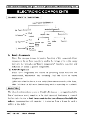
  • 1. www.infomaticaacademy.com XI - SCIENCE Email : info@infomaticaacademy.com ELECTRONIC COMPONENTS 39 il.com CLASSIFICATION OF COMPONENTS (a) Passive Components Since this category belongs to inactive functions of the component, these components do not have capacity to amplify the voltage or to rectify supply therefore, they are called as “Passive components”. Resistors, capacitors and Inductors are called as passive components. (b) Active Components Since these components are capable of performing active functions like amplification, rectification and switching, they are called as “active components”. (i) Electron tubes like Diode, triode and (ii) Semiconductor devices like diode, LED, Transistor etc.Electron tubes are rarely used because they are outdated. RESISTORS The value of resistance is measured in Ohm (  ). Resistance is the opposition to the flow of electrons or simply opposition to the electric current. Resistance is required in electronic circuits to limit the current, to drop the voltage and to divide the voltage. In combination with capacitor, it is used as filter or it can be used to achieve a time delay. ELECTRONIC COMPONENTS
  • 2. www.infomaticaacademy.com XI - SCIENCE Email : info@infomaticaacademy.com ELECTRONIC COMPONENTS 40  Types Of Resistors Resistors may be classified as (a) Fixed Resistors and (b) Variable Resistors. (A) Fixed Resistors Fixed resistors can be classified into three types according to the material used (1) Carbon types  (a) Carbon composition type, (b) Carbon film type. (2) Wire wound type (3) Metal film type (1) Carbon Composition Resistors These resistors are widely used in electronic circuits. Carbon composition resistor‟s value is available from 1 to about 20 M and typical power ratings are 1/5 W to 2W. Speciality of these resistors is low cost and small size. (Most of the resistors available in your laboratory are carbon composition type.). These resistorsare manufactured by mixing granules of carbon with binding material. This cylinder is molded in a cylindrical form as shown. Fig. (4.3) shows the construction and different wattages of resistors. Tinned copper wire leads are inserted in the two ends and structure is sealed with non-conducting coating. The cost of resistor depends on its wattage and not on the value of resistor.
  • 3. www.infomaticaacademy.com XI - SCIENCE Email : info@infomaticaacademy.com ELECTRONIC COMPONENTS 41  Colour coding of Carbon Resistor Method: In colour code method, the first two rings indicate the first two digits and the third ring indicates the multiplier. Fourth ring is used to indicate its tolerance.  Colour Code Chart Colour Value of the 1st and 2nd ring Value of 3rd ring (Multiplier ) Tolerance Black 0 X 0 10 Brown 1 X 1 10 ±1% Red 2 X 2 10 Orange 3 X 3 10 Yellow 4 X 4 10 Green 5 X 5 10 Blue 6 X 6 10 Violet 7 X 7 10 Gray 8 X 8 10 White or No Colour 9 X 9 10 ±20% Gold - X -1 10 ±5% Silver - X -2 10 ±10% EXAMPLES Find the value of carbon resistors by using colour code method. 2 )Re , ,Re 2 7 10 5% 27 100 2700 2.7 2 7 i d Violet d gold X X K or K       3 ) , , 1 0 10 10% 10 1000 10,000 10 ii Brown Black Orange Silver X X K      
  • 4. www.infomaticaacademy.com XI - SCIENCE Email : info@infomaticaacademy.com ELECTRONIC COMPONENTS 42 1 )Re ,Re , 2 2 10 5% 22 10 2.2 iii d d Gold Gold X       4 ) , , 5 0 10 10% 50 10000 500,000 500 0.5 iv Green Black Yellow Silver X x K M         (2) Carbon film Resistors This is another variety of carbon resistors in which a thin film of carbon is deposited on an insulating material like ceramic rod. During the deposition of the film, the value of resistance is adjusted by controlling the groove length and width of carbon film ribbon. Speciality: Low cost, Precision type. Range: 10 to10 M , Power rating upto 2W. (3) Wire Wound Resistors Wire wound resistor is used where high current control is required as well as where stable and accurate value of resistor is required. A wire wound resistor is manufactured by wrapping a length of special resistive wire like nichrome or mangenin around an insulating core of ceramic. The end of wire is attached to metal contacts,which are inserted in the core. After wire is wound, the whole structure is coated with enamel containing powdered glass and then heated to produce coating, this is known as vitreous enamel coating. It I required to protect the resistor and to dissipate the heat. Typical values are available in fraction of ohms to 100 K  . Power rating is from 5 W to 200 W. Speciality : Big in size, more power handling capacity. Colour code system is not used due to its big size. Ohm value is directly specified on the resistor. Range : Fraction of  to 100 100 K  and power rating 5 W TO 200 W.
  • 5. www.infomaticaacademy.com XI - SCIENCE Email : info@infomaticaacademy.com ELECTRONIC COMPONENTS 43 COMPARISON Carbon Composition Resistor Wire Wound Resistor 1. Carbon granules are used. A resistive wire like nichrome is used. 2. Tolerance is 2% to 20% More precision type because tolerance is very low. 3. Wide range of resistance. Available in low values only. 4. Low power ratings. High power ratings. 5. Color code system is used. No color code system is used. 6. Small size and low cost. Big size and high cost. (4) Metal Film Resistor ( MFR) These resistors are used for accurate value (precision type) because its tolerance is lessthan 5% . These resistors are manufactured in similar way to that of carbon film. Metal film of metal oxide or metal alloy is coated on a ceramic rod. There are different types of metal film like (1) Thin Film – Film layer is thin (2) Thick Film – Film layer is thick. Speciality : Low noise, good stability and tolerance less than 0.5% Range : 10 to 1 M. (B) VARIABLE RESISTORS Variable resistors are commonly called as rheostats. In low current circuit like in electronic circuit, small variable resistors are called as “potentiometer of pots”. Variable resistors are normally used in radio or audio equipment for volume control, and contrast and brightness control in TV sets. According to material used these resistors are classified into two types (1) Carbon type and (2) Wire wound type (1) Carbon Type Potentiometers Basically the construction of all potentiometers is same. In this type a movable metal pointer known as a „wiper‟ moves on a circular carbon resistive track as shown in fig. (4.6) this wiper is attached to a shift it may be metal or a plastic shaft.
  • 6. www.infomaticaacademy.com XI - SCIENCE Email : info@infomaticaacademy.com ELECTRONIC COMPONENTS 44 Variable resistors always have three terminals as shown, terminal 1 and 3 are fixed terminals and 2 is variable terminal. When terminal 1 and 3 are connected in the circuit you will get fixed and maximum resistance. When 1 and 2 or 2 and 3 terminals are connected you will get variation in resistance when you rotate the shaft. If you connect terminal 1 and 2 at extreme left side wiper will be at terminal 1, hence you will get zero resistance and when you rotate towards the right side its resistance increases. These variable resistors are available in two types, (1) Linear Type (2) Log Type. In linear potentiometer resistance varies with linear rate. If you rotate the shaft suppose for 0 10 rotation it gives 100 at 0 20  20 and so on. But in nonlinear potentiometer (log type) resistance varies in log scale, at 0 0 0 10 10 ,20 100 30 1000     . When the maximum range of resistance is required „Log type‟ pot is preferred. When often variation of resistance is required these carbon potentiometers are used like volume control but when rare adjustment is required small potentiometer called as “presets” are used. A power ON/OFF switch is commonly used with thee pots V/C with ON/OFF. Sometimes two or more resistor variation is required in synchronization. This type of potentiometer is called as “Gang pot”.
  • 7. www.infomaticaacademy.com XI - SCIENCE Email : info@infomaticaacademy.com ELECTRONIC COMPONENTS 45 Speciality: Low cost, Used in Radio, TV as volume control, brightness control etc. Range: 1K to 5 M, Power rating 1/2W to 2W. (2) Wire Wound Potentiometers: Basic principle of construction of wire wound variable resistor is simple; the most common example of this type is rheostat. In this type is wound on an open ring of ceramic, which is covered with vitreous enamel. The speciality of such type is high power handling capacity and very small and accurate change of resistance. Figure shows the constructions of wire wound pot and rheostat. In wire wound variable resistor non- linear resistor is also available (tapered type). Non-linearity in the resistor is achieved by using tapered stripon which resistive wire is wound fig… shows linear and non- linear potentiometer. By sliding the contact, the variation of resistance is achieved. Speciality: High Cost, Most power handling capacity, big size. Range: 100K to 1 M, Power rating 2W to 100 W.
  • 8. www.infomaticaacademy.com XI - SCIENCE Email : info@infomaticaacademy.com ELECTRONIC COMPONENTS 46 (C) OTHER RESISTORS Because of large development in semiconductor technology in addition to diode and transistors;special type of resistorsare manufactured which may be called as active resistors. (1) Thermistor A Thermistor is a semiconductor device whose resistance varies with temperature but change resistance is non-linear. Conductors show very small change in resistance but thermistor increase or decrease its resistance by more value. Hence thermistor can be NTC or PTC type. When resistance decreases with increase in temperature then then it is called as “Negative Temperature Coefficient” of resistance (NTC) and it is increases then it is called as “positive Temperature Coefficient” of resistance (PTC). Thermistors are used in many applications like measurement of temperature, temperature control, temperature compensation etc. (2) Light Dependent Resistor (LDR) It is a photosensitive device whose resistance decreases with increase in light intensity. The symbol is shown in fig. Cadmium sulfide material is used for this purpose. It‟s dark resistance is about 100K  and it decreases with increase in light. LDR is widely used in many application like automatic street light control, burglar alarm etc. (3) Varistor (VDR) It is also a non- linear resistor in which resistance is made variable to voltage. It is also known as voltage dependent resistor. They are two types. (i) Silicon Carbide VDR, (ii) Metal Oxide VDR. Varistor are used in industrial application and TV circuits to surge suppression.
  • 9. www.infomaticaacademy.com XI - SCIENCE Email : info@infomaticaacademy.com ELECTRONIC COMPONENTS 47 CAPACITORS Capacitor is second important passive component, commonly observed in electronic circuits.Many times it is called as condenser. Basically it is used to store electrical energy (by charging) and to deliver this stored energy (by discharging). This component has specific capacity of storing charge across it, hence named as capacitors. They are available in fixed and variable types; their capacity is measured in „farad‟. They are available in typical range of picofarads to microfarads. A capacitor consists of two parallel conducting surfaces separated by an insulator called as dielectric material. Different symbols of capacitor are shown in the fig... A capacitor is formed by two parallel conducting plates (may be spherical in structure) Separated by an insulating material.Insulating material like mica, paper, and ceramic called as “dielectric”. In electronic circuits capacitors plays an important role like resistor,it has got many applications such as in photo camera for flash, in power supplies used as a filter, in amplifiers as a coupling or a bypass capacitor and so on. Let us see its action of charging and discharging. As shown in the fig... When battery is connected across the capacitor, current flows through the circuit; current meter is connected for the indication.Before connecting the battery the number of electronson plate A and B are equal but when battery is connected across it, electronsare accumulated on plate A because they cannot flow
  • 10. www.infomaticaacademy.com XI - SCIENCE Email : info@infomaticaacademy.com ELECTRONIC COMPONENTS 48 through dielectric. An electrostatic force is developed by the plate A that gives a pressure to plate B. It passes the same number of electrons towards the battery. This is known as electrostatic induction. Thus we get negative charge on the plate A and positive on the plate B that produces a potential difference. Electrons continue to flow till voltage across capacitor becomes the battery voltage.Shows how capacitor voltage increases towardsbattery voltage and it shows current through it. Observe the graph when voltage across capacitor is „V‟ current is zero the process of charging is stopped. Remember, initially current is maximum and then it slowly decreases to zero. Formulae: (a) Capacitors in Series s 1 2 3 1 1 1 1 ....... C C C C     (b) Capacitors in Parallel 1 2 3 ....pC C C C    Example: 1) Two capacitors 20 μf and 5μf are connected in series and then connected in parallel the effective capacitance in each case. Solution In series In parallel 1 2 3 1 2 1 2 C C1 1 1 20 5 4μf C C C C +C 25       1 2 20 5 25μfpC C C    
  • 11. www.infomaticaacademy.com XI - SCIENCE Email : info@infomaticaacademy.com ELECTRONIC COMPONENTS 49 2) A capacitor of 0.2μf is connected in series with a resistance of 15MΩ. Find the time constant and the time required to charge up to battery voltage is 10V. What is the voltage across capacitor at 1 time constant? Solution 6 6 15 10 0.2 10 3sec.T R xc x             After 3 sec. the voltage acrosscapacitor is 63.2% of battery voltage i.e. 6.3 volts. It takes 3x 5 =15 seconds to charge up to 10 volts. TYPE OF CAPACITORS A) Fixed Capacitors Fixed capacitors can be classified according to the dielectric material and polar/ nonpolar such as, (i) Paper capacitor Non polar capacitor (ii) Mica capacitor Non polar capacitor (iii) Polyester capacitor Non polar capacitor (iv) Ceramic capacitor Non polar capacitor (v) Aluminium electric capacitorpolar capacitor (vi) Tantalum electric capacitorpolar capacitor (1) Paper Capacitors Basically the construction for all fixed non-polar capacitors is same. Two conducting surfaces are separated by electric material. Paper capacitor is manufactured by rolling two thin metal foils (foil is a long strip of metal) separated by a paper roll as shown in fig. Paper used for this purpose is Kraft paper impregnated with wax or resinor oil. Where, impregnation is the process in which paper is soaked with dielectric wax or oil.
  • 12. www.infomaticaacademy.com XI - SCIENCE Email : info@infomaticaacademy.com ELECTRONIC COMPONENTS 50 Speciality: Medium range of capacitance, small size and non- polar. Typical range: 500pF to 1μf and typically voltage rating from 100 V to 1000 V. (2) Mica Capacitors The construction is similar to that of paper capacitor only the die lectric material used is mica foil or mica sheet as shown. Mica capacitors are square or rectangular in shape with timed with leads. The entire structure is molded in Bakelite sheet. Speciality: High temperature range - o o 55 C to ±150 C Non- polar. Typical range: 5pF to 10,000 pF Voltage rating about 500V. (3) Ceramic Capacitor These capacitors are commonly observed in many circuits like amplifier, oscillators etc, as coupling capacitor. They are available in many different shapes like disc type, rectangular type, tabular and button type as shown in fig. The construction of ceramic capacitor is different than paper and mica capacitor. It is constructed by depositing silver plates on each side of a very thin of ceramic material.During the process tinned wire leads are attached to each plate. In this type colour code system is used but now values are directly printed on capacitor. It is also a non- polar capacitor. Speciality: Most economical in price 1 Rs. Per piece. Typical range: 3pF to 2 μF and voltage range from 3V to 6000 Volts non-polar.
  • 13. www.infomaticaacademy.com XI - SCIENCE Email : info@infomaticaacademy.com ELECTRONIC COMPONENTS 51 (4) Aluminium Electrolytic Capacitor This is a polar capacitor on which polarities are marked as positive and negative. Polarity is important because reverse connection may damage the capacitor. Another main difference between non- polar and polar; these capacitors are manufactured in higher values. Higher values are possible because electrolyte is used to provide more capacitance in smallest space. Electrolyticcapacitor consistsof Aluminium foil electrode as an aluminium oxide film covering one side and is in contact with an electron conducting fluid known as an electrolyte. The Aluminium oxide forms a dielectricand the electrolyte form another plate of capacitor. A layer of plain Aluminium foil is also wound into the capacitor to provide electrical contact betweenone of the terminals and electrolyte. (5) Tantalum Capacitors This is another type of electrolytic polar capacitor in which tantalum is used instead of aluminium.The construction is quite similar.The main advantage of tantalum is log shelf life, stable operation and greater temperature range. Disadvantages are high cost and low operating voltage. B) Variable Capacitors There is a need of variable capacitor in various circuits like tuning circuit of radio, oscillator circuit to vary the frequency etc. (1) Air Gang Capacitor Air gang condenser is a common example of variable capacitor. Other variable capacitors are similar to variable condenser but they are adjustable known as trimmers and padders. Gang condenser consists of two sets of parallel plates. One of the sets is fixed called as stator and another set is called as rotor. This rotor set of parallel plates is fitted on a movable shaft. When the shaft is rotated the area covered by each plate of rotor and stator
  • 14. www.infomaticaacademy.com XI - SCIENCE Email : info@infomaticaacademy.com ELECTRONIC COMPONENTS 52 is varied and thus total capacitance is varied. In valve type old ratio circuit two gang capacitors are used while in transistor receiver miniature type is used. Fig. shows simple construction of air gang capacitor. (2) Trimmers and Padders Since they are used for line tunning, they are constructed on the gang condenser itself they are called as trimmers and padders. Basically these are small variable capacitorsusing air, mica, ceramic as dielectric; some of the constructions are shown in fig. A screwdriver can be used to adjust the capacitance value. When rare variation of capacitance is required these capacitors are used. INDUCTORS Inductor is a third important passive component widely used in AC circuitsthan DC. Inductor is a simple coil of copper wound on a core material. Inductance is the ability of a conductor to produce an induced voltage,when current through it varies. In other words inductor opposes change in current. The unit of inductance is “Henry”. It is defined as the inductance that will develop a voltage of one volt across it when current changes at the rate of one Ampere per second or when a voltage of one volt is induced for the change of current rate 1 Amp/ Sec then the inductance of coil is said to be 1 Henry. INDUCTANCE It is the property of conductor to produce induced voltage, when current through it varies. Induced voltage is the result of change of flux across a conductor because when AC current flows through it magnetic flux varies its strength and the direction, which is equivalent to motion of the flux. When DC current flows through the conductor voltage induction is not possible induction is not possible because DC
  • 15. www.infomaticaacademy.com XI - SCIENCE Email : info@infomaticaacademy.com ELECTRONIC COMPONENTS 53 current is steady and it flows only in one direction. Inductor behaves like a conducting wire on DC.  Types Of Inductors Inductors can be classified into two groups as, (i) Fixed inductors (ii) Variable inductors.But they classified according to the material used for the core. (i) Air core inductors (ii) Iron core inductors (iii) Ferrite core inductors Another classification is also possible which is according to their application. In this classification the inductors are called as “Choke”. (i) Filter Choke (ii) RF Choke (iii) AF Choke (i) Air core Inductor In this type a length of conductor, copper wire is wound on a hollow tube. Here air acts as core, hence the name air- core inductor. The speciality this type is that there is maximum loss of magnetic flux and thus less flux is linked with the coil. It results in small value of inductance. (ii) Iron Core Inductor Here iron is placed in former of the coil so known as iron core inductors. Iron is a magnetic material, so when AC current through a coil the lines of flux re produced. These lines of flux pass through the iron core without any external leakage. When current passes through the iron core, iron becomes magnetized. Therefore, this iron adds its flux lines produced by the current. So the linesof flux increases i.e. The inductance of the coil increasesin iron core inductance than in air core inductor. The iron core inductor is commonly called as a choke.
  • 16. www.infomaticaacademy.com XI - SCIENCE Email : info@infomaticaacademy.com ELECTRONIC COMPONENTS 54 (iii) Ferrite Core Inductor Ferrite is an artificially made non- metallic material. When a Ferro- magnetic material is placed in former of the coil Ferrite core exhibits a minimum loss of lines of flux. It has high magnetic power and high resistivity to lines of flux. Ferrite core inductors are used for audio frequencies and radio frequencies. TRANSFORMERS A transformer consists of two inductors. One of these inductors is meant for supplying alternating current from an external source and is referred as a primary winding. In transformer, the coil in which the voltage is included is known as the secondary winding. A transformer works on the principle of mutual inductance. Hence, it is a device, which transfers alternating currents of high voltage to low voltage and vice- versa. It can also be step- up or step- down type as desired. Transfer is an important device in which voltage is transformed from one voltage level to other required level,For example, 230 Volt to 6V, 230V to 9V etc. This type of transformer is called as „step down’ transformer. Similarly 230V to 1KV, 230 V to 440V this type of transformer is called as „step- up‟ transformer. Transformer action is based on Faraday‟s law of electromagnetic mutual induction. As shown in the fig. transformer consists of two windings (coils). The winding which is normally connected to the mains is called as „primary winding’ and other winding across which output is obtained is called as „secondary winding’ sometimes more secondary winding, are used to get number of voltage by using same primary winding as 6V, 9V, 12V secondary taps. Both windings are wound on a core, which is laminated type.
  • 17. www.infomaticaacademy.com XI - SCIENCE Email : info@infomaticaacademy.com ELECTRONIC COMPONENTS 55  Working (principle) When an AC voltage is applied across its primary winding, AC current flows through it, therefore changing magnetic flux is produced. Secondary winding is kept close to the primary, which will cut this changing flux. According to Faraday‟s law, voltage is induced in the secondary wingding, the amount of induced voltage depends on the number of primary and secondary turns can be calculated by a ratio called as turns ratio. P P S S N V = N V …… Turns ratio Where PN =Number of turns in primary SN = Number of turns in secondary PV = Primary Voltage SV =Secondary voltage Remember,if we step down or step up the voltage from primary to secondary it affects current because power in primary and secondary is always equal. Similarly, the frequency of primary remains unchanged in secondary voltage. TRANSFORMER EFFICIENCY Transformer efficiency tells us the power loss in transformers; it specifies the wastage of energy. Transformer efficiency is calculated by formula   Output Power %Efficiency 100 Input Power    OR s s P p V ×I η= 100 V ×I  The efficiency of transformer is always less than 100% because of the following losses
  • 18. www.infomaticaacademy.com XI - SCIENCE Email : info@infomaticaacademy.com ELECTRONIC COMPONENTS 56 1. Copper loss It is the loss in primary and secondary winding because these voltage these are copper windings, which has small resistance. Due to this resistance,  2 I R energy is lost in these copper winding. Copper loss can be minimized by using thick copper wire. 2. Eddy Current loss When AC flows through a transformer voltage is not only induced in secondary winding in the core also, when voltage is induced in the iron core, current flows in the core, which is called as „eddy current’. 3. Hysteresis Loss Hysteresis means it is the curve plotted by applying magnetising force and observing the flux generated in the core material. Hysteresis curve indicates that magneticflux does not vary with magnetisingforce. It means suppose some flux is generated by magnetising force and if we make magnetising force zero then flux do not reduce to zero. Therefore, some extra energy is wasted in the core, which is called as „Hysteresis loss‟. TYPES OF TRANSFORMERS (1) Power Transformer Power transformersare also called as main transformers.i.e. they are meant to operate on the mains AC supply. They have one primary and one or several secondary windings. These secondary windings provide various operating voltages required for operating radio and other electronic equipments. (2) Audio Frequency Transformer Audio frequency transformer is made to operate on audio frequencies of the range of 20Hz. They are similar to the power transformers but differ in the core material. They are alwaysused to couple one stage to another.AF transformers are used in audio amplifiers for interstage coupling, for available in both types as stepup as well as stepdown. In power output stage of a radio receiver,a step audio frequency transformer is used to match high output impedance of the amplifier to low impedance of the speaker.
  • 19. www.infomaticaacademy.com XI - SCIENCE Email : info@infomaticaacademy.com ELECTRONIC COMPONENTS 57 (3) Radio Frequency Transformers Radio frequency transformers operate at very high frequencies. They are generally used with capacitors to form resonant circuits. At higher frequencies the eddy currents become effective. To reduce the eddy current lossesthe RF transformer is made of air core or iron- core transformer.Radio frequency transformersare used for interstage coupling and for coupling a signal to and from antenna. (4) Intermediate Frequency Transformers (IFT) Intermediate frequency lies between the audio frequency and radio frequency. These transformers are meant to operate at fixed frequency used is 455 KHz. They are also used in inter- carrier (TV receivers) sound section of Television. Other I.F. transformers with center frequency of the range of 39 MHz to 48 MHz are used in the video I.F. section of television (TV receivers). (5) Autotransformer In autotransformer a coil is used to provide turns for the primary as well as the secondary. When whole of the coil is used as primary and small part as secondary then it is called as step- up transformer.They are also provided with fixed of variable taps for varying secondary voltage. (6) Isolation Transformer When the number of turns of the primary is made equal to the number of secondary then the transformer formed is known as an isolation as an isolation transformer. It has 1 to 1 turns ratio, It reducesthe possibility of electric shock from the equipment.it is also used in audio frequency equipment and to block the DC component. SWITCHES An electrical switch is a mechanical device usually used to open (disconnect) or close (connect) an electrical circuit. (1) Single Pole Single Throw (SPST) Switch This type of switch can connect or discount only a single circuit. These are of two types- slide type and toggle type. A typical toggle type of SPST is shown in fig… its current rating is from 0.5 A to 6 A and voltage from 6V to 30V. It is primarily used as an ON-OFF switch in small electrical application e.g. a switch on electric switch board.
  • 20. www.infomaticaacademy.com XI - SCIENCE Email : info@infomaticaacademy.com ELECTRONIC COMPONENTS 58 (2) Single Pole Double (SPDT) Switch This type of switch has two ON positions. SPDT are also of two types- slide type and toggle SPDT switch. Toggle types are shown in fig... (3) Double Pole Single Throw (DPST) Switch Such type of switch has only one position of closure but two contacts (poles) simultaneously As shown in fig... They are of two types slide type DPST and toggle DPST. It is similar to a switch. The major difference in DPST switch is that both side of Two-wire line are switch at once. (4) Double Pole Double Throw (DPDT) Switch This type of switch has two poles and can be moved on either side,that is to the right or to the left as shown in fig... Two SPDT switchesconnected together can also be used as a DPDT switch. A toggle type DPDT is shown in fig. (a) while a side type DPDT is shown in fig. (b).
  • 21. www.infomaticaacademy.com XI - SCIENCE Email : info@infomaticaacademy.com ELECTRONIC COMPONENTS 59 (5) Micro Switches Micro switches are of various types. Basically they can be classified as illuminated rocker switch and subminiature rocker switch. But all the switches discussed above are toggle micro switches. They are suitable for both low level and high level (power switching) applications. (6) Band Switches These switches are used in instruments such as Radio, TV, Tape recorder, CRO to select a desired circuit. Mostly a three-band radio receiver set required a three- position band switch. These switchesare of different types- slide type or rotary type, as shown in fig… Industrial grade rotary switches are suitable for all types of test and industrial equipment and heavy use consumer products. (7) Thumb Wheel Switch s name suggest it is operated by thumb or fingers manually by adjusting digit on wheel of the switch. Its appearance is just like a speedometer of a monocycle. It is adjustable digital switch. RELAYS A relay is an electromagnetic device and it functions as an electrically operated switch, most of relays are operated electro- magnetically. When current flows through coil, electromagnetic field is generated, this attractsthe armature, which in turn opens or closes the electrical contacts. A common type of relay having a normally open (N/O) and a normally closed (N/C) contact as shown in fig. The normally closed contact provides continuity betweenthe armature and the upper contact. The spring holds the armature as shown. When a desired voltage is applied to the coil the armature is applied to the coil and it is pulled downwards. This breaks the normally closed (N/C) contact and makes the normally open contact (N/O). Now the continuity exits between the armature and the
  • 22. www.infomaticaacademy.com XI - SCIENCE Email : info@infomaticaacademy.com ELECTRONIC COMPONENTS 60 normally open contact (lower contact). A wide variety of relays are available in the study of electronic circuits.  Types of relay The different types of relay can be listed as follows (1) General purpose (Electromagnetic) relay (2) Power relay (3) Telephone relay (4) Card actuated relay (5) Sensitive relay (6) Crystal can relay (7) Dry reed relay (1) General purpose (Electromagnetic) Relay As shown in fig … it is an electromagnetic relay with its different parts labeled as under.in a way it is not special, but used since it is suitable in many applications and of low cost. When current flows through the coil the armature gets attracted towards the iron core. When electrical energy is applied, we say that the relay is energized. Thus the closed (N/C) and another to open contact Normally Open (N/O). The types of a general-purpose relay are as follows. (a) An iron core with a surrounding coil of wire. (b) A movable piece of iron called the armature with a set of contacts. (c) The armature is attached to the yoke. It is held by a spring so that there is an air- gap in the magnetic circuit.
  • 23. www.infomaticaacademy.com XI - SCIENCE Email : info@infomaticaacademy.com ELECTRONIC COMPONENTS 61  Specifications The relay specifications must be considered while selecting a relay. The following main specifications are listed by manufacture: (a) Current rating: It is the current drawn by the relay to energize it e.g. 200mA. (b) Voltage rating: it is the operating voltage of relay normally available in 6V, 9V, 12V, etc. (c) Contact Current rating:it is the maximum value of current which can pass though the contact without heating the elements. E.g. 1A, 2A, etc. (d) Number of contacts: it specifies number of poles. Simultaneously, operated when the relay is energized. E.g. Single pole, Two pole, Four Pole, etc. BATTERIES When the amount of power required is very small and if the electronic device is portable like tape recorder, electronic watch etc.a cell or battery is used as a source of electrical energy. When mains supply is not available then batteries play important role providing electrical energy for electronic circuits. Electrical energy generated with the helpof chemical reaction such type of device is called as „cell’ and if two or more cells are connected in series or parallel then unit is known as „Battery’. CELLS Cells can be classified into two types. (a) Primary cells (b) Secondary cells. Let us study the difference between primary and secondary cell and few examples. (a) Primary cell In this type one of the electrode delivers current by chemical reaction with electrolyte. But after few days electrode becomes weak and therefore electrode has to be replaced. Since these cells are not rechargeable it is known as primary cell. E.g. Carbon Zinc cell, alkaline cell etc.
  • 24. www.infomaticaacademy.com XI - SCIENCE Email : info@infomaticaacademy.com ELECTRONIC COMPONENTS 62 (b) Secondary cell It is rechargeable,known as secondary cell. It is defined as a cell in which the electrolyte is altered by chemical action that takes place when the cell delivers a current it can be restored to its original position by sending a current through it in opposite us study primary and two secondary cells. (1) Alkaline Manganese- Zinc cell (Dry cell) It is also referred as an alkaline cell. It has Zinc positive electrode and manganese dioxide as negative electrode. Cylindrical cathode sleeve or other surface is manganese dioxide to which outer steel can in contact. Zinc anode is also a cylindrical inner structure, which is in contact with upper portion as an anode terminal. These two electrodes are separated by potassium dihydroxide electrolyte.  Speciality This cell is comparatively big size cell is designed to provide high current for a long time. Typical voltage of this cell is 1.5 volts. This call is normally used in heater elements, horns, bicycle lights, aeroplanes and automobiles and in photoflashes units. (2) Lead- Acid Cell (Battery) Construction of such battery is shown in fig… it consists of spongy leads as a negative electrode plate and lead peroxide as a positive electrode plate. The electrolyte is a Sulfuric acid. The capacity of call is expressed in ampere-hours it depends on surface area of the electrodes or plates. In this structure, positive electrode plate is placed between two negative or plates. In this structure, positive and negative electrode, it is made up of hard rubber, wood, or plastics. Total unit is placed in a hard rubber container.
  • 25. www.infomaticaacademy.com XI - SCIENCE Email : info@infomaticaacademy.com ELECTRONIC COMPONENTS 63  Advantages (i) Typical voltage of cell is 2.2 volts with large current capacity. (ii) Relatively long life. (iii) Relatively low initial cost.  Disadvantages (i) Unit is heavy and big in size. (ii) Poor low temperature characteristics. (3) Nickel-cadmium cell This is more popular secondary cell used for high current circuits like portable tools, radios, Video camera etc. Standard Voltage is 1.25 V per cell; normally in sealed package. It can be recharged many times. Nickel- Cadmium cell has negative cadmium electrode and positive nickel electrode. The electrolyte is potassium hydroxide; it just acts as a conductor. Its recharging process is very fast and possess high gravity it does not loose its gravity rapidly. It has the main following parts. a) Steel body b) Separators c) +ve rod d) –ve containere) Cover. (4) Solar cell It is a special type of cell also known as photosensitive cell, when light is incident on its surface an EMG is generated across the cell. Its standard voltage is very low about 0.5 to 0.6 volts. They are connected in series and parallel combination to get sufficient output power.
  • 26. www.infomaticaacademy.com XI - SCIENCE Email : info@infomaticaacademy.com ELECTRONIC COMPONENTS 64 PRINTED CIRCUIT BOARDS (PCB) Printed circuit boards are extensively used for mounting electronic components with printed wiring on an insulating material. If we observe assembly of components in old electronic equipments we find it is more complicated. It has hard wiring of components. But this method was not superior and it was too difficult because of the following drawbacks: (i) Size of the circuit was too big. (ii) Each component was soldered with separate wire hence circuit was too complicated. (iii) It was difficult to repair the circuit. (iv) Assembly work was more time consuming because of such hard wiring. (v) After finishing the circuit the circuit the assembly was looking uneven.  Advantage of PCB Now this method of heard wiring has been completely replaced by a new technology of printed wiring called printed circuit boards. PCB‟s are preferred for over hard wiring because of the following advantages: 1. All wires re replaced by printed copper tracks therefore circuit requires very small size. 2. Uniform components assembly is possible which is more suitable in mass production of equipments. 3. Servicing of circuits becomes easier. 4. A large number of components can be assembled by using double sided board or multi- layer board. 5. Saving the assembly and inspection time.
  • 27. www.infomaticaacademy.com XI - SCIENCE Email : info@infomaticaacademy.com ELECTRONIC COMPONENTS 65 6. Low cost of production because one layout for a circuit once designed, a large number of PCB‟s can be prepared. 7. Easy to solder and de-solder the components 8. It provides mechanical support.  Types of PCB’s Different types of PCB‟s are manufactured. They can be classified according to material or laminate. A) Phenolic type B) Epoxy Type According to copper track design they are available in (1) Single sided (2) Double sided (3) Multi layers with PTH (Printed Through Holes) (4) Universal Boards. Where laminate is a base material on which conducting layer of copper is deposited. The thickness the copper is in micron, which decides the current carrying capacity. A) Phenolic Laminate Type (Paper Phenolic) Laminate is manufactured simply by pressing several layers of filler material. Filter material is either paper or glass and it is impregnated with either phenolic resin or epoxy polyester. After the impregnation process. Phenolic resin is absorbed in paper filter to form a rigid structure. Paper phenolic is most common type of PCB it is also known as “copper clad paper phenolic” laminate. Copper foil is pasted on Phenolic laminate. (This type you can observe in your laboratory). The colour of this board is dark brown. This is a low cost PCB, normally used for general application.  Drawbacks of paper Phenolic type (1) They are affected by alkalis (2) Poor arc resistance (3) Moisture may affect them. (4) They are non-transparent.
  • 28. www.infomaticaacademy.com XI - SCIENCE Email : info@infomaticaacademy.com ELECTRONIC COMPONENTS 66 B) Epoxy Laminate Type This is another important type of laminate; they are available in two types (i) Paper epoxy and (ii) Glass epoxy; Paper or glass is impregnated with epoxy resin. “Glass epoxy” is widely used in industries for manufacturing their instruments. This glass epoxy boards are manufactured by dipping glass cloth in epoxy solution, which hardened the final board, this material is costly than Phenolic type board. The colour of this board is faint greenish white. Epoxy laminate has following advantages. (i) They are more tough than other type and low shrinkage (ii) High alkali resistanc (iii) They do not get affected by moister and can withstand high temperature. (iv) Good chemical, electrical and water resistance (v) They are more transparent than Phenolic type, So easy to trace the tracks. There are other types of laminates such as polyester, silicon and PTFE laminates. But these types are not used on large scale. C) Single Sided Boards (SSB) In this type, copper foil is pasted only on one side components are mounted on the other side. The base material used is wither Phenolic or epoxy type. The density of component is limited. D) Double Sided Boards (DSB) In this type copper foil is pasted on both the sides of laminated and components are mounted on both sides. Large components are assembled on this board. PTH (Printed through holes) technique is employed to connect one side to other side. E) Multi- layer Board Multi-layer boards consists of a certain number of this PCB‟s stacked together and adhesively joined.Electrical connection different conductive layersare done with plated through holes PTH method. PTH means holes are made conductive to connect one layer to other layer of copper.
  • 29. www.infomaticaacademy.com XI - SCIENCE Email : info@infomaticaacademy.com ELECTRONIC COMPONENTS 67  Advantages (i) Very large number of components can be assembled. (ii) Size of the circuit can be reduced to very small. (iii) They provide low impedance.  Manufacturing Process Of Pcb’s Preparing a printed circuit board for a circuit is not so simple. A simple of processes are to be carried out to prepare a good PCB. There are two different methods of preparing PCB (i) Laboratory method-suitable for one or two boards. (ii) Industry photo resist method- Suitable for mass production.  Typing of Wires The classification of wires can be done by considering different factors like (i) According to the conducting material used (ii) According to hard or flexible structure (iii) According to the application and so on Some of the common types of wires are discussed here, Copper, Silver and Aluminum. The copper is most common; it is tinned copper in which a thin coating of solder material is provided.
  • 30. www.infomaticaacademy.com XI - SCIENCE Email : info@infomaticaacademy.com ELECTRONIC COMPONENTS 68 (1) Solid or Hard Wires These wires are commonly used in laboratory for connecting circuits or connecting electrical motors. They are also known as single stranded wires. A hard wire of copper or Aluminum is covered with insulating materials. The insulating material is rubber or plastic. Another example of such wires in the wiring of switchboards of electric supply. The main drawback of these wires is they may break anywhere in the circuit. (2) Stranded Wires The main advantages of these wires are, they are flexible and soft, less likely to break open. Stranded wire is composed of number of thin conductors of particular gauge e.g.14/36 wire means number of strands are 14 and gauge of each wire is 36. Similarly 7/34 in which number of strands is 7 and gauge of each strand is 34 and so on. These wires are called as bunch type. The other variety is also available known as concentricin which each strand is twisted with other as shown. Stranded wires are also called as “multistrand wire” (3) Shielded Coaxial Wires/cables These wires, you can see with CRO probes, microphone and tape recorder. Most of the audio equipments are connected through shielded wire. It consists of central conductor covered with insulating cover and this is covered with shield and one more outer jacked of insulator. The shielding is a mesh type structure, which is normally connected to chassis ground, to avoid external noise signal pick up.
  • 31. www.infomaticaacademy.com XI - SCIENCE Email : info@infomaticaacademy.com ELECTRONIC COMPONENTS 69 (4) Cotton or Silk covered Wire This type of wire is covered witha single or double layer of cotton or silk. It is used for the windings of inductors and transformers. The convering is a winding of fine threads over a bare wire. Double cotton- covered wires are generally used for the hookup of electronic components.The covering,different colours generally used for identification. These types of wires are used in radio frequency choke coils. (5) Power Cords and Cables Power cords and cables are used in circuits to complete the current flow. There must be a return path as well as forward path. If these paths are long they can be combined in a single unit. So it becomes a unit of parallel conductors called as power cord r power cable. (6) Twisted Wires This is a pair of conductors twisted together as shown. These wiresare usually rubber insulated. They are used in normal wiring for tubes, bulbs etc.